EP2248977A2 - Ferrure de guide d'une porte coulissante - Google Patents
Ferrure de guide d'une porte coulissante Download PDFInfo
- Publication number
- EP2248977A2 EP2248977A2 EP10161070A EP10161070A EP2248977A2 EP 2248977 A2 EP2248977 A2 EP 2248977A2 EP 10161070 A EP10161070 A EP 10161070A EP 10161070 A EP10161070 A EP 10161070A EP 2248977 A2 EP2248977 A2 EP 2248977A2
- Authority
- EP
- European Patent Office
- Prior art keywords
- guide
- sliding
- sliding door
- part housing
- running
- Prior art date
- Legal status (The legal status is an assumption and is not a legal conclusion. Google has not performed a legal analysis and makes no representation as to the accuracy of the status listed.)
- Granted
Links
Images


Classifications
-
- E—FIXED CONSTRUCTIONS
- E05—LOCKS; KEYS; WINDOW OR DOOR FITTINGS; SAFES
- E05D—HINGES OR SUSPENSION DEVICES FOR DOORS, WINDOWS OR WINGS
- E05D15/00—Suspension arrangements for wings
- E05D15/06—Suspension arrangements for wings for wings sliding horizontally more or less in their own plane
- E05D15/0621—Details, e.g. suspension or supporting guides
- E05D15/0626—Details, e.g. suspension or supporting guides for wings suspended at the top
- E05D15/0656—Bottom guides
-
- E—FIXED CONSTRUCTIONS
- E05—LOCKS; KEYS; WINDOW OR DOOR FITTINGS; SAFES
- E05D—HINGES OR SUSPENSION DEVICES FOR DOORS, WINDOWS OR WINGS
- E05D15/00—Suspension arrangements for wings
- E05D15/06—Suspension arrangements for wings for wings sliding horizontally more or less in their own plane
- E05D15/0621—Details, e.g. suspension or supporting guides
- E05D15/066—Details, e.g. suspension or supporting guides for wings supported at the bottom
- E05D15/0665—Details, e.g. suspension or supporting guides for wings supported at the bottom on wheels with fixed axis
- E05D15/0669—Details, e.g. suspension or supporting guides for wings supported at the bottom on wheels with fixed axis with height adjustment
- E05D15/0673—Details, e.g. suspension or supporting guides for wings supported at the bottom on wheels with fixed axis with height adjustment by vertical bolts
-
- E—FIXED CONSTRUCTIONS
- E05—LOCKS; KEYS; WINDOW OR DOOR FITTINGS; SAFES
- E05D—HINGES OR SUSPENSION DEVICES FOR DOORS, WINDOWS OR WINGS
- E05D15/00—Suspension arrangements for wings
- E05D15/06—Suspension arrangements for wings for wings sliding horizontally more or less in their own plane
- E05D15/0621—Details, e.g. suspension or supporting guides
- E05D15/066—Details, e.g. suspension or supporting guides for wings supported at the bottom
- E05D15/0682—Details, e.g. suspension or supporting guides for wings supported at the bottom on sliding blocks
-
- E—FIXED CONSTRUCTIONS
- E05—LOCKS; KEYS; WINDOW OR DOOR FITTINGS; SAFES
- E05D—HINGES OR SUSPENSION DEVICES FOR DOORS, WINDOWS OR WINGS
- E05D15/00—Suspension arrangements for wings
- E05D15/06—Suspension arrangements for wings for wings sliding horizontally more or less in their own plane
- E05D15/0621—Details, e.g. suspension or supporting guides
- E05D15/066—Details, e.g. suspension or supporting guides for wings supported at the bottom
- E05D15/0691—Top guides
-
- E—FIXED CONSTRUCTIONS
- E05—LOCKS; KEYS; WINDOW OR DOOR FITTINGS; SAFES
- E05Y—INDEXING SCHEME ASSOCIATED WITH SUBCLASSES E05D AND E05F, RELATING TO CONSTRUCTION ELEMENTS, ELECTRIC CONTROL, POWER SUPPLY, POWER SIGNAL OR TRANSMISSION, USER INTERFACES, MOUNTING OR COUPLING, DETAILS, ACCESSORIES, AUXILIARY OPERATIONS NOT OTHERWISE PROVIDED FOR, APPLICATION THEREOF
- E05Y2600/00—Mounting or coupling arrangements for elements provided for in this subclass
- E05Y2600/10—Adjustable
- E05Y2600/30—Adjustment motion
- E05Y2600/31—Linear motion
- E05Y2600/314—Vertical motion
-
- E—FIXED CONSTRUCTIONS
- E05—LOCKS; KEYS; WINDOW OR DOOR FITTINGS; SAFES
- E05Y—INDEXING SCHEME ASSOCIATED WITH SUBCLASSES E05D AND E05F, RELATING TO CONSTRUCTION ELEMENTS, ELECTRIC CONTROL, POWER SUPPLY, POWER SIGNAL OR TRANSMISSION, USER INTERFACES, MOUNTING OR COUPLING, DETAILS, ACCESSORIES, AUXILIARY OPERATIONS NOT OTHERWISE PROVIDED FOR, APPLICATION THEREOF
- E05Y2600/00—Mounting or coupling arrangements for elements provided for in this subclass
- E05Y2600/50—Mounting methods; Positioning
- E05Y2600/52—Toolless
- E05Y2600/53—Snapping
-
- E—FIXED CONSTRUCTIONS
- E05—LOCKS; KEYS; WINDOW OR DOOR FITTINGS; SAFES
- E05Y—INDEXING SCHEME ASSOCIATED WITH SUBCLASSES E05D AND E05F, RELATING TO CONSTRUCTION ELEMENTS, ELECTRIC CONTROL, POWER SUPPLY, POWER SIGNAL OR TRANSMISSION, USER INTERFACES, MOUNTING OR COUPLING, DETAILS, ACCESSORIES, AUXILIARY OPERATIONS NOT OTHERWISE PROVIDED FOR, APPLICATION THEREOF
- E05Y2600/00—Mounting or coupling arrangements for elements provided for in this subclass
- E05Y2600/50—Mounting methods; Positioning
- E05Y2600/56—Positioning, e.g. re-positioning, or pre-mounting
-
- E—FIXED CONSTRUCTIONS
- E05—LOCKS; KEYS; WINDOW OR DOOR FITTINGS; SAFES
- E05Y—INDEXING SCHEME ASSOCIATED WITH SUBCLASSES E05D AND E05F, RELATING TO CONSTRUCTION ELEMENTS, ELECTRIC CONTROL, POWER SUPPLY, POWER SIGNAL OR TRANSMISSION, USER INTERFACES, MOUNTING OR COUPLING, DETAILS, ACCESSORIES, AUXILIARY OPERATIONS NOT OTHERWISE PROVIDED FOR, APPLICATION THEREOF
- E05Y2800/00—Details, accessories and auxiliary operations not otherwise provided for
- E05Y2800/15—Applicability
- E05Y2800/17—Universally applicable
- E05Y2800/172—Universally applicable on different wing or frame locations
- E05Y2800/174—Universally applicable on different wing or frame locations on the left or right side
-
- E—FIXED CONSTRUCTIONS
- E05—LOCKS; KEYS; WINDOW OR DOOR FITTINGS; SAFES
- E05Y—INDEXING SCHEME ASSOCIATED WITH SUBCLASSES E05D AND E05F, RELATING TO CONSTRUCTION ELEMENTS, ELECTRIC CONTROL, POWER SUPPLY, POWER SIGNAL OR TRANSMISSION, USER INTERFACES, MOUNTING OR COUPLING, DETAILS, ACCESSORIES, AUXILIARY OPERATIONS NOT OTHERWISE PROVIDED FOR, APPLICATION THEREOF
- E05Y2800/00—Details, accessories and auxiliary operations not otherwise provided for
- E05Y2800/26—Form or shape
- E05Y2800/292—Form or shape having apertures
-
- E—FIXED CONSTRUCTIONS
- E05—LOCKS; KEYS; WINDOW OR DOOR FITTINGS; SAFES
- E05Y—INDEXING SCHEME ASSOCIATED WITH SUBCLASSES E05D AND E05F, RELATING TO CONSTRUCTION ELEMENTS, ELECTRIC CONTROL, POWER SUPPLY, POWER SIGNAL OR TRANSMISSION, USER INTERFACES, MOUNTING OR COUPLING, DETAILS, ACCESSORIES, AUXILIARY OPERATIONS NOT OTHERWISE PROVIDED FOR, APPLICATION THEREOF
- E05Y2800/00—Details, accessories and auxiliary operations not otherwise provided for
- E05Y2800/40—Physical or chemical protection
- E05Y2800/424—Physical or chemical protection against unintended use, e.g. protection against vandalism or sabotage
- E05Y2800/426—Physical or chemical protection against unintended use, e.g. protection against vandalism or sabotage against unauthorised use, e.g. keys
-
- E—FIXED CONSTRUCTIONS
- E05—LOCKS; KEYS; WINDOW OR DOOR FITTINGS; SAFES
- E05Y—INDEXING SCHEME ASSOCIATED WITH SUBCLASSES E05D AND E05F, RELATING TO CONSTRUCTION ELEMENTS, ELECTRIC CONTROL, POWER SUPPLY, POWER SIGNAL OR TRANSMISSION, USER INTERFACES, MOUNTING OR COUPLING, DETAILS, ACCESSORIES, AUXILIARY OPERATIONS NOT OTHERWISE PROVIDED FOR, APPLICATION THEREOF
- E05Y2800/00—Details, accessories and auxiliary operations not otherwise provided for
- E05Y2800/74—Specific positions
- E05Y2800/742—Specific positions abnormal
-
- E—FIXED CONSTRUCTIONS
- E05—LOCKS; KEYS; WINDOW OR DOOR FITTINGS; SAFES
- E05Y—INDEXING SCHEME ASSOCIATED WITH SUBCLASSES E05D AND E05F, RELATING TO CONSTRUCTION ELEMENTS, ELECTRIC CONTROL, POWER SUPPLY, POWER SIGNAL OR TRANSMISSION, USER INTERFACES, MOUNTING OR COUPLING, DETAILS, ACCESSORIES, AUXILIARY OPERATIONS NOT OTHERWISE PROVIDED FOR, APPLICATION THEREOF
- E05Y2900/00—Application of doors, windows, wings or fittings thereof
- E05Y2900/20—Application of doors, windows, wings or fittings thereof for furniture, e.g. cabinets
Definitions
- the present invention relates to a guide fitting a sliding door of a sliding door furniture with a guide member according to the preamble of claim 1 and a guide fitting a sliding door of a sliding door furniture with a running part according to the preamble of claim. 5
- Generic guide fittings for sliding doors of example sliding door furniture have a guide part as a slider for an upper guide and a running part as a slider with a role for a lower guide.
- the guide member consists of a guide part housing with a sliding member which projects from below into a guide profile of a ceiling part of a sliding door furniture to guide the sliding door.
- the sliding element is pressed permanently with a compression spring upwards and thereby projects into the guide profile.
- a disadvantage of such a guide fitting is that the locking of the sliding element in the guide part housing does not provide secure theft protection, ie the sliding element can be pressed down in a very simple manner by pressing down the sliding member with a flat object, such as a bank card, from the outside of the door.
- a disadvantage is further that for sliding doors, which are considered in different depths, ie in a horizontal plane to be performed at different distances from the cabinet body, other guide fittings are to be mounted in the respective cabinet door, which in particular causes higher storage costs by stockpiling different guide fittings.
- Object of the present invention is therefore to provide a guide fitting a sliding door with a guide part, which provides a secure anti-theft device and with an adjustment of the depth of the guide is made possible in a simple manner.
- Another object of the present invention is to provide a guide fitting a sliding door with a running part, which is usable for sliding doors that are to be performed at different depths.
- a latching tongue is arranged on the sliding element of the guide fitting according to claim 1, which can be locked with a perpendicular to the direction of displacement of the sliding element locking element of the guide part housing.
- the adjusting member and the running element are formed as a unit which can be used in rotated by 180 degrees positions in the running part housing.
- a simple removal of the unit from the Laufteilgepatuse is made possible to turn around 180 Degree to perform, so that, as needed, the sliding element in front and the rear wheel or the slider can be arranged at the rear and the front wheel.
- such a trained guide fitting can be used for two different sliding depths.
- a mouth-like-shaped end is formed on the detent tongue on its side facing the detent element in order to at least partially surround a detent element of the guide part housing designed as a strut.
- the latching tongue is formed above the mouth-like shaped end with a handle member which is accessible via a provided in the guide part housing above the latching element second opening.
- top, bottom, left, right, front, back, etc. refer exclusively to the example representation of the position of the guide fitting and other parts selected in the respective figures. These terms are not meant to be limiting, i. H. in different working positions or the mirror-symmetrical design or the like, these references may change.
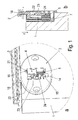
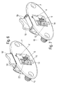
- a sliding door 1 of a sliding door furniture is provided for guiding a sliding door in an example U-shaped guide profile 2, wherein the guide profile 2 is preferably embedded in a ceiling part of the sliding door furniture.
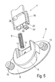
- the guide fitting 3 has, as in particular in Fig. 4 and 5 is clearly visible, a guide part housing 7, in which a provided with lateral guide webs 19 sliding member 4 is mounted vertically displaceable. From the cuboid shaped main body of the sliding member 4 projects upwards a guide web 18 out, which in its functional position from below into a in the Fig. 1 to 3 shown guide profile 2 of a sliding door furniture protrudes to guide the sliding door.
- a guide web 18 out which in its functional position from below into a in the Fig. 1 to 3 shown guide profile 2 of a sliding door furniture protrudes to guide the sliding door.
- a cylindrical opening 20 is provided, in which a spring element 5, preferably in the form of a compression spring, can be inserted, which rests with its other end in a cylindrical opening 12 in the guide part housing 6.
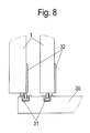
- the spring element 5 presses the sliding element 4 permanently upwards into the guide profile 2 of the sliding door furniture. So that the sliding element 4 is not completely pushed out of the guide part housing 6, a stop 21 is formed on the sliding element 4, which stops the sliding element 4 in the guide part housing 6.
- a recess 16 corresponding to the shape of the stop 21 is formed on the upper edge of a rectangular housing recess 13.
- the housing recess 13 makes available a latching tongue 22, which is arranged on the sliding element 4 and which can be latched with a latching element 15 of the guide part housing 6 running perpendicularly to the displacement direction z of the sliding element 4.
- the latching tongue 22 is formed on its side facing the latching element 15 with a mouth-like-shaped end 24 which can engage around the latching element 15 at least partially.
- the locking element 15 is preferably formed as a strut, behind which the guide part housing 6 is formed with a further recess 17 which is connected to the front side 7 of the guide part housing 6 with a first opening 14.
- the guide part housing 6 further has on its rear side 8 for attachment to the sliding door 1, two dowels 10, which are used in holes provided in the sliding door 1 and can be screwed by the screwed from the front side 7 of the guide part housing 6 ago screws.
- the latching tongue 22 is resiliently arranged on the sliding element 4 and can be by pushing a formed approximately centrally on the latching tongue 22 grip element 23 from the front side 7 of the guide part housing 6 ago in the guide part housing Press in 6.
- the jaw-shaped end 24 of the latching tongue 22 protrudes approximately L-shaped to the front side 7 of the guide part housing 6.
- the sliding element 4 allows a theft security in the guide fitting 3.
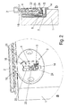
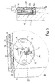
- the sliding element 4 can in particular occupy three functional positions, which in the Fig. 1 to 3 are shown.
- Fig. 1 the slider 4 is in an upper position.
- the stop 21 of the sliding member 4 touches the housing recess 16 of the guide member housing 6 and the mouth-like shaped end 24 of the latching tongue 22 is located in this position above the locking element 15.
- the sliding member 4 of the guide bar 18 of the sliding member 4 dives from below into the Guide profile 2 of the sliding door furniture.
- the sliding element 4 To disassemble the sliding door 1, the sliding element 4 must first be lowered from the guide profile 2. For this purpose, a user has to slide the sliding element 4 against the spring force of the spring element 5 via the grip element 23 of the latching tongue 22. If the handle element 23 is not pressed back into the guide part housing 6, then the mouth-like-shaped end 24 of the latching tongue 22 sets on the latching element 15 from above. As a result, the sliding element 4 can not be pushed further down. In this position, the guide web 18 of the sliding element 4 still protrudes a little way into the guide profile 2, so that the sliding door 1 can not yet be dismantled in this state.
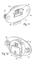
- the sliding element 4 is conceivable in different variants.
- the corresponding in Fig. 7 shown variant of the sliding element 4 of the variant in the Fig. 1 to 5 in which the guide web 18 is formed as an extension of a rear wall of the sliding element 4 while the in Fig. 6 shown variant of the sliding element 4 has a guide web 18 ', which is designed as an extension of a front wall, ie the front side 7 of the guide part housing 6 facing wall of the sliding member 4'.
- a positioning of the guide web 18 at intermediate locations is also conceivable.
- 6 different guide depths is made possible by simply replacing the sliding elements 4, 4 'in a guide part housing.
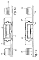
- a guide fitting 32 is described on the sliding door 1 to the lower guide in a preferably inserted into a bottom 30 of a sliding door furniture guide rail 31.
- This guide fitting 32 has a running part housing 33 with an adjusting 44.
- a height-adjustable mounted race member 34 is arranged, which has an impeller 43 and a sliding member 42. By the impeller 43, the sliding of the sliding door 1 is facilitated in the sliding door furniture.
- the running part housing 33 has on its back for attachment to the sliding door 1, two dowels 35 which are inserted into holes provided in the sliding door 1 and can be screwed by the screwed from the front side 38 of the running part housing 33 ago screws.
- the adjusting member 44 and the running element 34 are formed as a one-piece unit which can be inserted from below into a cylindrical housing portion 37 of the running part housing 33.
- this is formed with lateral guide webs 46, which eino in grooves 36 of the raceway housing 33.
- the adjusting member 44 is in Mounting direction arranged above the running element 34 and preferably designed as a thumbwheel.
- a cylindrical adapter piece 45 extends into a cylindrical recess 40 in a surface of the running part housing 33 designed as a support surface 39.
- locking webs 41 are arranged around the cylindrical opening 40 on the support surface 39 of the running part housing hold the adjusting member 44 frictionally in the once set position.
- a running element housing 47 surrounding the impeller 43 and the sliding element 42 is designed such that it can be inserted into the traveling part housing 33 in two different positions, in particular in positions turned by 180 °. This ensures that, in particular in the FIGS. 13 and 14 can be seen, in an installed position, the sliding member 42 is disposed on a side facing the front side 38 of the running part housing 33 and the impeller 43 behind or the sliding member 42 is in the rear position and the impeller 43 is in the forward position.
- the runners 34 can thus be used by simply turning 180 degrees for two different sliding door guide depths.
Landscapes
- Engineering & Computer Science (AREA)
- Mechanical Engineering (AREA)
- Support Devices For Sliding Doors (AREA)
- Wing Frames And Configurations (AREA)
- Cabinets, Racks, Or The Like Of Rigid Construction (AREA)
- Hinges (AREA)
Priority Applications (4)
| Application Number | Priority Date | Filing Date | Title |
|---|---|---|---|
| PL10161070T PL2248977T3 (pl) | 2009-05-06 | 2010-04-26 | Okucie prowadzące drzwi przesuwnych |
| PL15154338T PL2891758T3 (pl) | 2009-05-06 | 2010-04-26 | Okucie prowadnicowe drzwi przesuwnych, drzwi przesuwne i mebel z drzwiami przesuwnymi |
| EP15154338.6A EP2891758B1 (fr) | 2009-05-06 | 2010-04-26 | Ferrure de guidage d'une porte coulissante, porte coulissante et meuble à porte coulissante |
| SI201031205A SI2248977T1 (sl) | 2009-05-06 | 2010-04-26 | Vodilno okovje drsnih vrat |
Applications Claiming Priority (1)
| Application Number | Priority Date | Filing Date | Title |
|---|---|---|---|
| DE202009004790U DE202009004790U1 (de) | 2009-05-06 | 2009-05-06 | Führungsbeschlag einer Schiebetür |
Related Child Applications (2)
| Application Number | Title | Priority Date | Filing Date |
|---|---|---|---|
| EP15154338.6A Division EP2891758B1 (fr) | 2009-05-06 | 2010-04-26 | Ferrure de guidage d'une porte coulissante, porte coulissante et meuble à porte coulissante |
| EP15154338.6A Division-Into EP2891758B1 (fr) | 2009-05-06 | 2010-04-26 | Ferrure de guidage d'une porte coulissante, porte coulissante et meuble à porte coulissante |
Publications (3)
| Publication Number | Publication Date |
|---|---|
| EP2248977A2 true EP2248977A2 (fr) | 2010-11-10 |
| EP2248977A3 EP2248977A3 (fr) | 2014-08-06 |
| EP2248977B1 EP2248977B1 (fr) | 2016-04-13 |
Family
ID=42556764
Family Applications (2)
| Application Number | Title | Priority Date | Filing Date |
|---|---|---|---|
| EP10161070.7A Active EP2248977B1 (fr) | 2009-05-06 | 2010-04-26 | Ferrure de guide d'une porte coulissante |
| EP15154338.6A Active EP2891758B1 (fr) | 2009-05-06 | 2010-04-26 | Ferrure de guidage d'une porte coulissante, porte coulissante et meuble à porte coulissante |
Family Applications After (1)
| Application Number | Title | Priority Date | Filing Date |
|---|---|---|---|
| EP15154338.6A Active EP2891758B1 (fr) | 2009-05-06 | 2010-04-26 | Ferrure de guidage d'une porte coulissante, porte coulissante et meuble à porte coulissante |
Country Status (5)
| Country | Link |
|---|---|
| EP (2) | EP2248977B1 (fr) |
| DE (1) | DE202009004790U1 (fr) |
| ES (1) | ES2577550T3 (fr) |
| PL (2) | PL2248977T3 (fr) |
| SI (1) | SI2248977T1 (fr) |
Cited By (8)
| Publication number | Priority date | Publication date | Assignee | Title |
|---|---|---|---|---|
| JP2016510370A (ja) * | 2013-01-30 | 2016-04-07 | ヘティッヒ‐ハインゼ ゲーエムベーハー ウント ツェーオー. カーゲー | ガイドレールを介して誘導方向に家具部品を誘導するための走行部、および家具用建具 |
| US20170159325A1 (en) * | 2015-12-03 | 2017-06-08 | Lawrence E. Chaffin | Lift glide door lock assembly & lift glide window lock assembly |
| DE102016101869A1 (de) * | 2016-02-03 | 2017-08-03 | Maco Technologie Gmbh | Beschlaganordnung |
| DE102017125252A1 (de) * | 2017-10-27 | 2019-05-02 | Roto Frank Ag | Führungsbeschlag für einen Schiebeflügel |
| US11085205B2 (en) | 2017-11-28 | 2021-08-10 | Accurate Lock & Hardware Co. Llc | Sliding door locking system |
| WO2022096629A1 (fr) * | 2020-11-09 | 2022-05-12 | Hettich-Heinze Gmbh & Co. Kg | Meuble et procédé de montage d'une porte coulissante sur un corps de meuble |
| WO2023209001A1 (fr) * | 2022-04-28 | 2023-11-02 | Ikea Supply Ag | Rail de coulissement ayant un canal ouvert |
| WO2025099622A1 (fr) * | 2023-11-08 | 2025-05-15 | Punto Finestre S.P.A. | Vantail coulissant d'une fenêtre et système de vantail coulissant |
Families Citing this family (1)
| Publication number | Priority date | Publication date | Assignee | Title |
|---|---|---|---|---|
| DE102023122941A1 (de) * | 2023-08-25 | 2025-02-27 | Dethleffs Gmbh & Co. Kg | Freizeitfahrzeug, Schiebetür und Federelement für Schiebetüren von Freizeitfahrzeugen |
Family Cites Families (7)
| Publication number | Priority date | Publication date | Assignee | Title |
|---|---|---|---|---|
| US1780755A (en) * | 1928-04-23 | 1930-11-04 | Garden City Plating And Mfg Co | Roller or caster |
| US2944282A (en) * | 1959-08-17 | 1960-07-12 | Greco Michael | Concealable partitions |
| BE772850A (fr) * | 1970-09-25 | 1972-01-17 | Kleine Hermann J | Porte coulissante constituee par une plaque de grande surface |
| US4123874A (en) * | 1977-01-31 | 1978-11-07 | Leigh Products, Inc. | By-pass door assembly |
| DE8912544U1 (de) * | 1989-10-23 | 1990-04-05 | Trola Kunststofferzeugnisse GmbH, 8501 Schwaig | Riegel für Schiebetüren von Möbeln |
| DE19653897B4 (de) * | 1996-12-21 | 2006-09-21 | Palme Sanitär-Vertriebsgesellschaft m.b.H. | Führungsanordnung für ein Türelement |
| ATE346211T1 (de) * | 1999-12-13 | 2006-12-15 | Eku Ag | Laufwerkanordnung für eine schiebetür |
-
2009
- 2009-05-06 DE DE202009004790U patent/DE202009004790U1/de not_active Expired - Lifetime
-
2010
- 2010-04-26 PL PL10161070T patent/PL2248977T3/pl unknown
- 2010-04-26 PL PL15154338T patent/PL2891758T3/pl unknown
- 2010-04-26 ES ES10161070.7T patent/ES2577550T3/es active Active
- 2010-04-26 EP EP10161070.7A patent/EP2248977B1/fr active Active
- 2010-04-26 SI SI201031205A patent/SI2248977T1/sl unknown
- 2010-04-26 EP EP15154338.6A patent/EP2891758B1/fr active Active
Non-Patent Citations (1)
| Title |
|---|
| None |
Cited By (12)
| Publication number | Priority date | Publication date | Assignee | Title |
|---|---|---|---|---|
| JP2016510370A (ja) * | 2013-01-30 | 2016-04-07 | ヘティッヒ‐ハインゼ ゲーエムベーハー ウント ツェーオー. カーゲー | ガイドレールを介して誘導方向に家具部品を誘導するための走行部、および家具用建具 |
| US20170159325A1 (en) * | 2015-12-03 | 2017-06-08 | Lawrence E. Chaffin | Lift glide door lock assembly & lift glide window lock assembly |
| US10526829B2 (en) * | 2015-12-03 | 2020-01-07 | Lawrence E Chaffin | Lift glide door lock assembly and lift glide window lock assembly |
| DE102016101869A1 (de) * | 2016-02-03 | 2017-08-03 | Maco Technologie Gmbh | Beschlaganordnung |
| DE102017125252A1 (de) * | 2017-10-27 | 2019-05-02 | Roto Frank Ag | Führungsbeschlag für einen Schiebeflügel |
| US11085205B2 (en) | 2017-11-28 | 2021-08-10 | Accurate Lock & Hardware Co. Llc | Sliding door locking system |
| WO2022096629A1 (fr) * | 2020-11-09 | 2022-05-12 | Hettich-Heinze Gmbh & Co. Kg | Meuble et procédé de montage d'une porte coulissante sur un corps de meuble |
| CN116472391A (zh) * | 2020-11-09 | 2023-07-21 | 海蒂诗-海因策有限及两合公司 | 家具和用于将滑动门安装在家具主体上的方法 |
| EP4477831A2 (fr) | 2020-11-09 | 2024-12-18 | Hettich-Heinze GmbH & Co. KG | Meuble et procédé de montage d'une porte coulissante sur un corps de meuble |
| EP4477831A3 (fr) * | 2020-11-09 | 2025-02-12 | Hettich-Heinze GmbH & Co. KG | Meuble et procédé de montage d'une porte coulissante sur un corps de meuble |
| WO2023209001A1 (fr) * | 2022-04-28 | 2023-11-02 | Ikea Supply Ag | Rail de coulissement ayant un canal ouvert |
| WO2025099622A1 (fr) * | 2023-11-08 | 2025-05-15 | Punto Finestre S.P.A. | Vantail coulissant d'une fenêtre et système de vantail coulissant |
Also Published As
| Publication number | Publication date |
|---|---|
| EP2248977A3 (fr) | 2014-08-06 |
| EP2891758A3 (fr) | 2015-07-29 |
| PL2248977T3 (pl) | 2017-04-28 |
| EP2891758A2 (fr) | 2015-07-08 |
| ES2577550T3 (es) | 2016-07-15 |
| EP2248977B1 (fr) | 2016-04-13 |
| PL2891758T3 (pl) | 2019-01-31 |
| DE202009004790U1 (de) | 2010-09-23 |
| EP2891758B1 (fr) | 2018-08-08 |
| SI2248977T1 (sl) | 2016-07-29 |
Similar Documents
| Publication | Publication Date | Title |
|---|---|---|
| EP2891758B1 (fr) | Ferrure de guidage d'une porte coulissante, porte coulissante et meuble à porte coulissante | |
| DE102013216974A1 (de) | Kühlschrank | |
| AT511905A1 (de) | Schublade | |
| EP3147435B1 (fr) | Dispositif d'arret d'extraction et meuble | |
| EP3291702B1 (fr) | Meuble et procédé pour fixer un tiroir | |
| EP3153646A1 (fr) | Verrou de fenêtre et/ou porte | |
| EP3684223B1 (fr) | Dispositif d'accouplement destiné à un tiroir à encliquetage postérieur | |
| EP2281482B1 (fr) | Dispositifs d'éjection d'un guidage d'extraction et guidage d'extraction | |
| EP2951374B1 (fr) | Pièce coulissante servant à guider une partie de meuble dans un sens de guidage sur une glissière et ferrure de meuble | |
| EP1997989B2 (fr) | Elément de glissement pour un guide de porte coulisante | |
| DE102015116612A1 (de) | Beschlag für eine Schiebetür und Verfahren zur Montage einer Schiebetür | |
| EP2078812A2 (fr) | Elément de recouvrement pour un rail de guidage | |
| EP2505744A2 (fr) | Plaque de fermeture pour un battant de porte ou de fenêtre déposé d'un dormant | |
| EP1747334A1 (fr) | Poignee creuse | |
| DE102012200430B4 (de) | Schiebetüren- oder -fensteranlage mit mindestens zwei als Tür oder Fenster ausgebildeten Schiebeelementen sowie Verriegelungseinrichtung hierfür | |
| DE102016118466B4 (de) | Mitnehmer zur Verriegelung eines Innenschubes und Möbelauszug | |
| DE202010008370U1 (de) | Schnappriegelvorrichtung | |
| DE4016285A1 (de) | Schubriegelverschluss | |
| DE102014109437A1 (de) | Beschlag für eine Schiebetür | |
| DE102012103251A1 (de) | Berührungsschutzabdeckung für elektrische Anlagen | |
| DE3143638A1 (de) | Schliesszylinder | |
| EP3797646B1 (fr) | Dispositif de raccordement permettant de raccorder les parois de tiroir, paroi de tiroir et meuble | |
| DE10142470C1 (de) | Fehlbedienungssicherung für Treibstangenbeschläge | |
| EP2132391A1 (fr) | Ensemble tringle de crémone constitué d'au moins une tringle et d'au moins un élément de guidage de tringle | |
| EP1905929A1 (fr) | Dispositif pour arrêter une fenêtre |
Legal Events
| Date | Code | Title | Description |
|---|---|---|---|
| PUAI | Public reference made under article 153(3) epc to a published international application that has entered the european phase |
Free format text: ORIGINAL CODE: 0009012 |
|
| AK | Designated contracting states |
Kind code of ref document: A2 Designated state(s): AT BE BG CH CY CZ DE DK EE ES FI FR GB GR HR HU IE IS IT LI LT LU LV MC MK MT NL NO PL PT RO SE SI SK SM TR |
|
| AX | Request for extension of the european patent |
Extension state: AL BA ME RS |
|
| RIC1 | Information provided on ipc code assigned before grant |
Ipc: E05D 15/06 20060101AFI20140320BHEP |
|
| PUAL | Search report despatched |
Free format text: ORIGINAL CODE: 0009013 |
|
| AK | Designated contracting states |
Kind code of ref document: A3 Designated state(s): AT BE BG CH CY CZ DE DK EE ES FI FR GB GR HR HU IE IS IT LI LT LU LV MC MK MT NL NO PL PT RO SE SI SK SM TR |
|
| AX | Request for extension of the european patent |
Extension state: AL BA ME RS |
|
| RIC1 | Information provided on ipc code assigned before grant |
Ipc: E05D 15/06 20060101AFI20140701BHEP |
|
| 17P | Request for examination filed |
Effective date: 20150205 |
|
| RBV | Designated contracting states (corrected) |
Designated state(s): AT BE BG CH CY CZ DE DK EE ES FI FR GB GR HR HU IE IS IT LI LT LU LV MC MK MT NL NO PL PT RO SE SI SK SM TR |
|
| GRAP | Despatch of communication of intention to grant a patent |
Free format text: ORIGINAL CODE: EPIDOSNIGR1 |
|
| INTG | Intention to grant announced |
Effective date: 20150723 |
|
| INTG | Intention to grant announced |
Effective date: 20151208 |
|
| GRAS | Grant fee paid |
Free format text: ORIGINAL CODE: EPIDOSNIGR3 |
|
| GRAA | (expected) grant |
Free format text: ORIGINAL CODE: 0009210 |
|
| AK | Designated contracting states |
Kind code of ref document: B1 Designated state(s): AT BE BG CH CY CZ DE DK EE ES FI FR GB GR HR HU IE IS IT LI LT LU LV MC MK MT NL NO PL PT RO SE SI SK SM TR |
|
| REG | Reference to a national code |
Ref country code: GB Ref legal event code: FG4D Free format text: NOT ENGLISH |
|
| REG | Reference to a national code |
Ref country code: AT Ref legal event code: REF Ref document number: 790367 Country of ref document: AT Kind code of ref document: T Effective date: 20160415 Ref country code: CH Ref legal event code: EP |
|
| REG | Reference to a national code |
Ref country code: IE Ref legal event code: FG4D Free format text: LANGUAGE OF EP DOCUMENT: GERMAN |
|
| REG | Reference to a national code |
Ref country code: DE Ref legal event code: R096 Ref document number: 502010011415 Country of ref document: DE |
|
| REG | Reference to a national code |
Ref country code: CH Ref legal event code: NV Representative=s name: ISLER AND PEDRAZZINI AG, CH |
|
| REG | Reference to a national code |
Ref country code: FR Ref legal event code: PLFP Year of fee payment: 7 |
|
| REG | Reference to a national code |
Ref country code: ES Ref legal event code: FG2A Ref document number: 2577550 Country of ref document: ES Kind code of ref document: T3 Effective date: 20160715 |
|
| REG | Reference to a national code |
Ref country code: LT Ref legal event code: MG4D |
|
| PG25 | Lapsed in a contracting state [announced via postgrant information from national office to epo] |
Ref country code: BE Free format text: LAPSE BECAUSE OF NON-PAYMENT OF DUE FEES Effective date: 20160430 |
|
| REG | Reference to a national code |
Ref country code: NL Ref legal event code: MP Effective date: 20160413 |
|
| PG25 | Lapsed in a contracting state [announced via postgrant information from national office to epo] |
Ref country code: FI Free format text: LAPSE BECAUSE OF FAILURE TO SUBMIT A TRANSLATION OF THE DESCRIPTION OR TO PAY THE FEE WITHIN THE PRESCRIBED TIME-LIMIT Effective date: 20160413 Ref country code: NL Free format text: LAPSE BECAUSE OF FAILURE TO SUBMIT A TRANSLATION OF THE DESCRIPTION OR TO PAY THE FEE WITHIN THE PRESCRIBED TIME-LIMIT Effective date: 20160413 Ref country code: NO Free format text: LAPSE BECAUSE OF FAILURE TO SUBMIT A TRANSLATION OF THE DESCRIPTION OR TO PAY THE FEE WITHIN THE PRESCRIBED TIME-LIMIT Effective date: 20160713 Ref country code: LT Free format text: LAPSE BECAUSE OF FAILURE TO SUBMIT A TRANSLATION OF THE DESCRIPTION OR TO PAY THE FEE WITHIN THE PRESCRIBED TIME-LIMIT Effective date: 20160413 |
|
| PG25 | Lapsed in a contracting state [announced via postgrant information from national office to epo] |
Ref country code: GR Free format text: LAPSE BECAUSE OF FAILURE TO SUBMIT A TRANSLATION OF THE DESCRIPTION OR TO PAY THE FEE WITHIN THE PRESCRIBED TIME-LIMIT Effective date: 20160714 Ref country code: PT Free format text: LAPSE BECAUSE OF FAILURE TO SUBMIT A TRANSLATION OF THE DESCRIPTION OR TO PAY THE FEE WITHIN THE PRESCRIBED TIME-LIMIT Effective date: 20160816 Ref country code: LV Free format text: LAPSE BECAUSE OF FAILURE TO SUBMIT A TRANSLATION OF THE DESCRIPTION OR TO PAY THE FEE WITHIN THE PRESCRIBED TIME-LIMIT Effective date: 20160413 Ref country code: HR Free format text: LAPSE BECAUSE OF FAILURE TO SUBMIT A TRANSLATION OF THE DESCRIPTION OR TO PAY THE FEE WITHIN THE PRESCRIBED TIME-LIMIT Effective date: 20160413 Ref country code: SE Free format text: LAPSE BECAUSE OF FAILURE TO SUBMIT A TRANSLATION OF THE DESCRIPTION OR TO PAY THE FEE WITHIN THE PRESCRIBED TIME-LIMIT Effective date: 20160413 |
|
| REG | Reference to a national code |
Ref country code: DE Ref legal event code: R097 Ref document number: 502010011415 Country of ref document: DE |
|
| REG | Reference to a national code |
Ref country code: IE Ref legal event code: MM4A |
|
| PG25 | Lapsed in a contracting state [announced via postgrant information from national office to epo] |
Ref country code: DK Free format text: LAPSE BECAUSE OF FAILURE TO SUBMIT A TRANSLATION OF THE DESCRIPTION OR TO PAY THE FEE WITHIN THE PRESCRIBED TIME-LIMIT Effective date: 20160413 Ref country code: SK Free format text: LAPSE BECAUSE OF FAILURE TO SUBMIT A TRANSLATION OF THE DESCRIPTION OR TO PAY THE FEE WITHIN THE PRESCRIBED TIME-LIMIT Effective date: 20160413 Ref country code: MC Free format text: LAPSE BECAUSE OF FAILURE TO SUBMIT A TRANSLATION OF THE DESCRIPTION OR TO PAY THE FEE WITHIN THE PRESCRIBED TIME-LIMIT Effective date: 20160413 Ref country code: RO Free format text: LAPSE BECAUSE OF FAILURE TO SUBMIT A TRANSLATION OF THE DESCRIPTION OR TO PAY THE FEE WITHIN THE PRESCRIBED TIME-LIMIT Effective date: 20160413 Ref country code: EE Free format text: LAPSE BECAUSE OF FAILURE TO SUBMIT A TRANSLATION OF THE DESCRIPTION OR TO PAY THE FEE WITHIN THE PRESCRIBED TIME-LIMIT Effective date: 20160413 Ref country code: CZ Free format text: LAPSE BECAUSE OF FAILURE TO SUBMIT A TRANSLATION OF THE DESCRIPTION OR TO PAY THE FEE WITHIN THE PRESCRIBED TIME-LIMIT Effective date: 20160413 |
|
| PLBE | No opposition filed within time limit |
Free format text: ORIGINAL CODE: 0009261 |
|
| STAA | Information on the status of an ep patent application or granted ep patent |
Free format text: STATUS: NO OPPOSITION FILED WITHIN TIME LIMIT |
|
| PG25 | Lapsed in a contracting state [announced via postgrant information from national office to epo] |
Ref country code: SM Free format text: LAPSE BECAUSE OF FAILURE TO SUBMIT A TRANSLATION OF THE DESCRIPTION OR TO PAY THE FEE WITHIN THE PRESCRIBED TIME-LIMIT Effective date: 20160413 |
|
| 26N | No opposition filed |
Effective date: 20170116 |
|
| REG | Reference to a national code |
Ref country code: FR Ref legal event code: PLFP Year of fee payment: 8 |
|
| PG25 | Lapsed in a contracting state [announced via postgrant information from national office to epo] |
Ref country code: IE Free format text: LAPSE BECAUSE OF NON-PAYMENT OF DUE FEES Effective date: 20160426 |
|
| REG | Reference to a national code |
Ref country code: AT Ref legal event code: MM01 Ref document number: 790367 Country of ref document: AT Kind code of ref document: T Effective date: 20160426 |
|
| PG25 | Lapsed in a contracting state [announced via postgrant information from national office to epo] |
Ref country code: AT Free format text: LAPSE BECAUSE OF NON-PAYMENT OF DUE FEES Effective date: 20160426 |
|
| REG | Reference to a national code |
Ref country code: DE Ref legal event code: R084 Ref document number: 502010011415 Country of ref document: DE |
|
| REG | Reference to a national code |
Ref country code: FR Ref legal event code: PLFP Year of fee payment: 9 |
|
| PG25 | Lapsed in a contracting state [announced via postgrant information from national office to epo] |
Ref country code: HU Free format text: LAPSE BECAUSE OF FAILURE TO SUBMIT A TRANSLATION OF THE DESCRIPTION OR TO PAY THE FEE WITHIN THE PRESCRIBED TIME-LIMIT; INVALID AB INITIO Effective date: 20100426 Ref country code: CY Free format text: LAPSE BECAUSE OF FAILURE TO SUBMIT A TRANSLATION OF THE DESCRIPTION OR TO PAY THE FEE WITHIN THE PRESCRIBED TIME-LIMIT Effective date: 20160413 |
|
| PG25 | Lapsed in a contracting state [announced via postgrant information from national office to epo] |
Ref country code: LU Free format text: LAPSE BECAUSE OF NON-PAYMENT OF DUE FEES Effective date: 20160426 Ref country code: MT Free format text: LAPSE BECAUSE OF FAILURE TO SUBMIT A TRANSLATION OF THE DESCRIPTION OR TO PAY THE FEE WITHIN THE PRESCRIBED TIME-LIMIT Effective date: 20160413 Ref country code: IS Free format text: LAPSE BECAUSE OF FAILURE TO SUBMIT A TRANSLATION OF THE DESCRIPTION OR TO PAY THE FEE WITHIN THE PRESCRIBED TIME-LIMIT Effective date: 20160413 Ref country code: MK Free format text: LAPSE BECAUSE OF FAILURE TO SUBMIT A TRANSLATION OF THE DESCRIPTION OR TO PAY THE FEE WITHIN THE PRESCRIBED TIME-LIMIT Effective date: 20160413 |
|
| PG25 | Lapsed in a contracting state [announced via postgrant information from national office to epo] |
Ref country code: BG Free format text: LAPSE BECAUSE OF FAILURE TO SUBMIT A TRANSLATION OF THE DESCRIPTION OR TO PAY THE FEE WITHIN THE PRESCRIBED TIME-LIMIT Effective date: 20160413 |
|
| REG | Reference to a national code |
Ref country code: ES Ref legal event code: GC2A Effective date: 20200729 |
|
| REG | Reference to a national code |
Ref country code: GB Ref legal event code: 746 Effective date: 20201013 |
|
| PGFP | Annual fee paid to national office [announced via postgrant information from national office to epo] |
Ref country code: FR Payment date: 20210421 Year of fee payment: 12 |
|
| PGFP | Annual fee paid to national office [announced via postgrant information from national office to epo] |
Ref country code: GB Payment date: 20210422 Year of fee payment: 12 Ref country code: SI Payment date: 20210414 Year of fee payment: 12 |
|
| GBPC | Gb: european patent ceased through non-payment of renewal fee |
Effective date: 20220426 |
|
| PG25 | Lapsed in a contracting state [announced via postgrant information from national office to epo] |
Ref country code: GB Free format text: LAPSE BECAUSE OF NON-PAYMENT OF DUE FEES Effective date: 20220426 Ref country code: FR Free format text: LAPSE BECAUSE OF NON-PAYMENT OF DUE FEES Effective date: 20220430 |
|
| REG | Reference to a national code |
Ref country code: SI Ref legal event code: KO00 Effective date: 20221208 |
|
| PG25 | Lapsed in a contracting state [announced via postgrant information from national office to epo] |
Ref country code: SI Free format text: LAPSE BECAUSE OF NON-PAYMENT OF DUE FEES Effective date: 20220427 |
|
| P01 | Opt-out of the competence of the unified patent court (upc) registered |
Effective date: 20230404 |
|
| PGFP | Annual fee paid to national office [announced via postgrant information from national office to epo] |
Ref country code: ES Payment date: 20230517 Year of fee payment: 14 |
|
| REG | Reference to a national code |
Ref country code: ES Ref legal event code: FD2A Effective date: 20250530 |
|
| PGFP | Annual fee paid to national office [announced via postgrant information from national office to epo] |
Ref country code: DE Payment date: 20250417 Year of fee payment: 16 Ref country code: PL Payment date: 20250411 Year of fee payment: 16 |
|
| PG25 | Lapsed in a contracting state [announced via postgrant information from national office to epo] |
Ref country code: ES Free format text: LAPSE BECAUSE OF NON-PAYMENT OF DUE FEES Effective date: 20240427 |
|
| PGFP | Annual fee paid to national office [announced via postgrant information from national office to epo] |
Ref country code: IT Payment date: 20250430 Year of fee payment: 16 |
|
| PGFP | Annual fee paid to national office [announced via postgrant information from national office to epo] |
Ref country code: CH Payment date: 20250501 Year of fee payment: 16 |
|
| PGFP | Annual fee paid to national office [announced via postgrant information from national office to epo] |
Ref country code: TR Payment date: 20250418 Year of fee payment: 16 |