EP2248982B1 - Kopplungselement für Fensterrahmen, Fassaden oder dergleichen - Google Patents
Kopplungselement für Fensterrahmen, Fassaden oder dergleichen Download PDFInfo
- Publication number
- EP2248982B1 EP2248982B1 EP20100004846 EP10004846A EP2248982B1 EP 2248982 B1 EP2248982 B1 EP 2248982B1 EP 20100004846 EP20100004846 EP 20100004846 EP 10004846 A EP10004846 A EP 10004846A EP 2248982 B1 EP2248982 B1 EP 2248982B1
- Authority
- EP
- European Patent Office
- Prior art keywords
- coupling element
- element according
- seal
- gap
- figur
- Prior art date
- Legal status (The legal status is an assumption and is not a legal conclusion. Google has not performed a legal analysis and makes no representation as to the accuracy of the status listed.)
- Not-in-force
Links
- 230000008878 coupling Effects 0.000 title claims description 82
- 238000010168 coupling process Methods 0.000 title claims description 82
- 238000005859 coupling reaction Methods 0.000 title claims description 82
- 229910000831 Steel Inorganic materials 0.000 claims description 28
- 239000010959 steel Substances 0.000 claims description 28
- AZDRQVAHHNSJOQ-UHFFFAOYSA-N alumane Chemical group [AlH3] AZDRQVAHHNSJOQ-UHFFFAOYSA-N 0.000 claims description 15
- 229910052751 metal Inorganic materials 0.000 claims description 14
- 239000002184 metal Substances 0.000 claims description 14
- 230000004888 barrier function Effects 0.000 claims description 9
- 238000007789 sealing Methods 0.000 claims description 6
- 239000000463 material Substances 0.000 claims description 4
- 229910052782 aluminium Inorganic materials 0.000 description 9
- XAGFODPZIPBFFR-UHFFFAOYSA-N aluminium Chemical compound [Al] XAGFODPZIPBFFR-UHFFFAOYSA-N 0.000 description 9
- 239000004033 plastic Substances 0.000 description 8
- 229920003023 plastic Polymers 0.000 description 8
- 238000009413 insulation Methods 0.000 description 6
- 238000012546 transfer Methods 0.000 description 5
- 239000004411 aluminium Substances 0.000 description 4
- 230000009467 reduction Effects 0.000 description 4
- 230000015572 biosynthetic process Effects 0.000 description 3
- 238000013461 design Methods 0.000 description 3
- 238000009434 installation Methods 0.000 description 2
- 238000005096 rolling process Methods 0.000 description 2
- 239000000853 adhesive Substances 0.000 description 1
- 230000001070 adhesive effect Effects 0.000 description 1
- 238000004873 anchoring Methods 0.000 description 1
- 150000001875 compounds Chemical class 0.000 description 1
- 238000010276 construction Methods 0.000 description 1
- 238000009749 continuous casting Methods 0.000 description 1
- 230000002349 favourable effect Effects 0.000 description 1
- 239000011152 fibreglass Substances 0.000 description 1
- 239000003365 glass fiber Substances 0.000 description 1
- 238000007373 indentation Methods 0.000 description 1
- 238000003780 insertion Methods 0.000 description 1
- 230000037431 insertion Effects 0.000 description 1
- 238000012423 maintenance Methods 0.000 description 1
- 230000014759 maintenance of location Effects 0.000 description 1
- 238000004519 manufacturing process Methods 0.000 description 1
- 238000005457 optimization Methods 0.000 description 1
- 230000002787 reinforcement Effects 0.000 description 1
- 238000007493 shaping process Methods 0.000 description 1
- 230000003068 static effect Effects 0.000 description 1
Images





Classifications
-
- E—FIXED CONSTRUCTIONS
- E06—DOORS, WINDOWS, SHUTTERS, OR ROLLER BLINDS IN GENERAL; LADDERS
- E06B—FIXED OR MOVABLE CLOSURES FOR OPENINGS IN BUILDINGS, VEHICLES, FENCES OR LIKE ENCLOSURES IN GENERAL, e.g. DOORS, WINDOWS, BLINDS, GATES
- E06B1/00—Border constructions of openings in walls, floors, or ceilings; Frames to be rigidly mounted in such openings
- E06B1/56—Fastening frames to the border of openings or to similar contiguous frames
- E06B1/60—Fastening frames to the border of openings or to similar contiguous frames by mechanical means, e.g. anchoring means
- E06B1/6007—Fastening frames to the border of openings or to similar contiguous frames by mechanical means, e.g. anchoring means between similar contiguous frames
Definitions
- the invention relates to a coupling element for window frames, facades or the like.
- the invention relates to a coupling element for the arrangement between two profiles of adjacent frame, in particular plastic windows and doors.
- Such coupling elements are for example from the DE 20 304 167 U1 , of the DE 198 55 966 A1 and the DE 101 56 898 A1 known.
- Coupling elements hold together frame. They must therefore meet special static requirements. In addition, an important aspect is the seal between the coupling element and the frame. Finally, the heat transfer in the area between the frame and from the outside of the façade to the façade inside must be kept to a minimum.
- the invention is based on the object of developing such coupling elements.
- this object is achieved with a generic coupling element having an undercut groove for a seal with a locking foot.
- the groove is formed in an aluminum part or a sheet metal part.
- an aluminum part can be provided as part of the coupling element, in particular when using a continuous casting in a simple manner an undercut groove.
- a steel sheet has an inferior thermal conductivity compared to an aluminum part and is therefore particularly suitable for producing a coupling element in heat-insulating facades.
- a special rolling process makes it possible to provide the undercut groove in the coupling element.
- the coupling element has sheet metal parts which are positively connected, preferably hook-like, with each other. This simplifies the manufacturing process and reduces the heat transfer.
- the positive connection of sheet metal parts with each other or with a Insulating body is also essential to the invention, regardless of the specific design of the groove.
- a further reduction of the heat transfer, in particular from the inside of the facade to the outside of the facade is achieved in that the coupling element has a heat flow barrier.
- a heat flow barrier is achieved, for example, by connecting an outer part of the coupling element to a heat-insulating middle part and connecting this middle part to an inner part of the coupling element.
- the middle part can be a plastic part. Particularly preferred is a glass fiber reinforced plastic part is used.
- the heat flow barrier has a hollow body.
- the hollow body combines good stability with good thermal insulation.
- This hollow body is preferably formed from a plastic part.
- the heat flow barrier is formed by holes in a region between a part facing a frame inside and a part facing a frame outside.
- a particular embodiment provides that the heat flow barrier is held positively in the coupling element.
- an undercut groove is preferably provided in an aluminum part, and in the case of a sheet metal part, the sheet is preferably shaped such that a preferably undercut groove results over which a formed example as a plastic part heat flow barrier can be positively held.
- the coupling element has a gap with a structured surface. This makes it possible to insert a spike or a web of a cover in the gap and keep it there safe. Especially with long bars and long columns, the tension between the legs of the bridge is often not enough to keep the cover safely.
- a PVC or plastic cover can be kept particularly well between the legs of a shaped profile of sheet metal.
- the gap has longitudinal notches which extend in the direction of the longitudinal extension of the coupling element.
- the structure thus runs transversely to the insertion direction of a cover and it can be easily provided in the profile during the rolling process.
- the gap between sheet metal surfaces is formed and the depth of the structure is less than half the thickness of a sheet on which the structure is arranged.
- the structure has, for example, a depth between 0.1 and 2 mm.
- a particularly favorable design of the seal provides that the seal is made of a harder material for the Rastfuß and a softer material is coextruded. This allows a generally soft design of the seal and at the same time a particularly secure anchoring of the seal in the undercut groove by means of the harder formed locking foot.
- the invention provides that the seal has a groove. This groove can serve the connection with the adjacent blind profiles.
- the invention further provides that the seal is connected via a tongue and groove connection with the coupling element.
- the seal can then be held and positioned via the tongue and groove connection on a web of the coupling element, while a particularly firm connection of the seal with another part of the coupling element is formed by the locking foot.
- a special embodiment of the seal provides that a groove of the seal opposite the undercut groove.
- the grooves thus have oppositely directed openings for optimum connection to ensure between the seal and the remaining parts of the coupling element.
- the coupling element has a cover with a hollow chamber for standing air, wherein the hollow chamber in cross section has a gap with a width of less than 3 mm and preferably less than 2 mm.
- a cover is usually formed as a PVC cover.
- the gap is preferably transverse to the longitudinal extent of the coupling element.
- the cover is formed as a plastic extruded profile, such gaps extend for thermal insulation along at least one outer side of the profile.
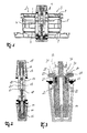
- FIG. 1 shows in each case a cross section through a longitudinally extending coupling element which has either aluminum extruded profiles or rolled sheet metal profiles.
- Coupling element 1 shown connects two frame profiles 2 and 3.
- screws 4, 5 respectively screwed by the coupling element in the profile of the frame 2, 3.
- the frame profiles have reinforcements 6, 7, 8 and 9, which extend in the longitudinal direction of the screws and transversely to the coupling element.
- the coupling element essentially consists of a first extruded aluminum part 10, a second extruded aluminum part 11 and an insulating body 12 arranged therebetween.
- the extruded aluminum parts have a gap 13, 14 in the middle, which serves to receive a dome or a screw for fastening a cover 15, 16.
- This insulating body 12 is made of plastic and has cavities 19, 20, 21 for insulation optimization. To increase the stability of the plastic may be glass fiber reinforced.
- At least on one side of the coupling element 1 is a transverse to the columns 13 and 14 extending groove 22, 23 provided in the aluminum part 11.
- the opposite grooves 22 and 23 serve to receive a seal 24, 25.
- the seal has a reinforced sealing foot 26, 27 and a preferably coextruded connected in cross-section hook-shaped softer sealing region 28, 29th This hook-shaped sealing region 28, 29 has in each case a groove 30, 31, which is slipped over a web 32, 33.
- seals 24, 25 can thus be easily positioned over the webs 32 and 33 and the sealing feet 26 and 27 provide a secure fit in preferably undercut grooves 22 and 23 of the aluminum part eleventh
- the formation of the coupling element of an insulating body 12 and aluminum parts 10, 11 allows a wide variety of embodiments of coupling elements for different applications.
- Embodiments are in the FIGS. 4 to 7 shown. This show the FIGS. 5 to 7 in that the aluminum part can be extended in a simple manner by a curved sheet metal part 34, 35. This enables further embodiments and serves to reduce the heat transfer.
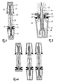
- FIGS. 8 to 13 Different embodiments of coupling elements made of steel are in the FIGS. 8 to 13 shown.
- two differently shaped steel sheets 36, 37 are connected to each other at the point 38. This results in columns 39, 40 for receiving a dome or a screw for the attachment of a cover 41, 42nd
- the steel sheets are shaped such that grooves 45, 46 for receiving a sealing foot 47, 48 of the seals 43, 44 are formed.
- Perforations, embossments 49 or partial cross-sectional reductions are used for attachment and in particular the reduction the heat transfer.
- Special indentations 50 on the gap 51 may enhance the retention of a dome 52 or screw (not shown).
- Coupling elements of two sheet steel profiles 56 and 57 with an insulating body 58 are in the FIGS. 14 to 17 shown.
- the insulating body 58 is held positively in an undercut groove formed in the sheet metal profile.
- FIG. 18 The installation of such a coupling element 59 between two frame profiles 60 and 61 is in FIG. 18 shown. A slightly different dimensioning of such a coupling profile shows the FIG. 19 ,
- a particularly simple construction of a coupling element 62 shows the FIG. 20 , Here are two steel sheets 63 and 64 connected to each other, so that two columns 65, 66 and two screw receptacles 67, 68 arise.
- Longitudinal bores 69, 70 serve as mounting holes and perforations 71 for reducing the thermal conductivity.
- cross-sectional reductions by perforations and / or rows of holes in the offset (elongated holes) are suitable for reducing the thermal conductivity.
- the special shape of the sheet at one end allows the formation of grooves 72, 73 for receiving seals (not shown).
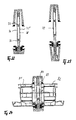
- FIGS. 22 to 24 show how by a special shaping of the sheets 74 and 75 hook-like compounds 76 and 77 can be formed, while perforations 78, 79 serve to reduce the thermal conductivity and can be used as screw channels.
- the coupling profile in the FIGS. 22 to 24 has covers as caps, which have a narrow elongated gap in section. This gap is so narrow that the air circulation is minimized in the gap, so that the gap has particularly good thermal insulation properties.
- the thickness of the gap is less than 2 mm and the length of the gap extends parallel to the outside of the cap.
- FIG. 24 shows the installation of such a profile 80 between two frame profiles 81 and 82 with the interposition of expansion plates 83rd
- the attachment of a dome 84 or a screw 85 can be improved by a serration structure 86 within a gap 87 of a coupling element 88.
- the serration structure 86 is formed as corrugations transversely to the extent of the gap 87. This facilitates both the maintenance of a dome, which is preferably also jagged structured, as well as a screw 85. This is especially for very long columns 87 in which the bias of the sheet metal parts is no longer sufficient to keep the screw or a mandrel safe.
Landscapes
- Engineering & Computer Science (AREA)
- Mechanical Engineering (AREA)
- Civil Engineering (AREA)
- Structural Engineering (AREA)
- Wing Frames And Configurations (AREA)
Description
- Die Erfindung betrifft ein Kopplungselement für Fensterrahmen, Fassaden oder dergleichen. Insbesondere betrifft die Erfindung ein Kopplungselement zur Anordnung zwischen zwei Profilen benachbarter Blendrahmen, insbesondere Kunststoff-Fenstern und -Türen. Derartige Kopplungselemente sind beispielsweise aus der
DE 20 304 167 U1 , derDE 198 55 966 A1 und derDE 101 56 898 A1 bekannt. - Des weiteren ist aus der
DE 92 07 578 U1 ein Kopplungselement mit allen Merkmalen des Oberbegriffs von Anspruch 1 offenbart. - Kopplungselemente halten Blendrahmen zusammen. Sie müssen daher besonderen statischen Anforderungen genügen. Darüber hinaus ist ein wichtiger Aspekt die Abdichtung zwischen Kopplungselement und Blendrahmen. Letztlich muss auch der Wärmeübergang im Bereich zwischen den Blendrahmen und von der Fassadenaußenseite zur Fassadeninnenseite minimal gehalten werden.
- Daraus ergeben sich unterschiedliche Anforderungen an ein Kopplungselement. Der Erfindung liegt die Aufgabe zu Grunde derartige Kopplungselemente weiterzubilden.
- Diese Aufgabe wird mit den Merkmalen des karakterisierenden Teils von Anspruch 1 gelöst.
- Nach einem ersten Aspekt der Erfindung wird diese Aufgabe mit einem gattungsgemäßen Kopplungselement gelöst, das eine hinterschnittene Nut für eine Dichtung mit einem Rastfuß aufweist.
- Die Befestigung der Dichtung mittels eines Rastfußes in einer hinterschnittenen Nut führt dazu, dass die Dichtung auch dann sicher am Kopplungselement befestigt ist, wenn keine Klebeverbindung vorgesehen wird. Sie hält auch auf verschmutzten Oberflächen und sie ist einfach anzubringen, indem der Rastfuß in die hierfür vorgesehene hinterschnittene Nut hineingedrückt wird. Dies erlaubt ein manuelles als auch ein automatisches Anbringen der Dichtung in der Nut.
- Es ist vorgesehen, dass die Nut in einem Aluminiumteil oder einem Stahblechteil ausgebildet ist. In einem Aluminiumteil kann als Teil des Kopplungselementes insbesondere bei der Verwendung eines Stranggussteils auf einfache Art und Weise eine hinterschnittene Nut vorgesehen sein.
- Ein Stahlblech hat gegenüber einem Aluminium-teil eine schlechtere Wärmeleitfähigkeit und eignet sich daher besonders gut zur Herstellung eines Kopplungselementes in wärmeisolierenden Fassaden. Ein spezieller Walzvorgang ermöglicht es die hinterschnittene Nut im Kopplungselement vorzusehen.
- Insbesondere bei der Verwendung von Stahlblechteilen wird vorgeschlagen, dass das Kopplungselement Blechteile aufweist, die formschlüssig, vorzugsweise hakenartig, miteinander verbunden sind. Hierdurch wird das Herstellungsverfahren vereinfacht und der Wärmeübergang reduziert. Die formschlüssige Verbindung von Blechteilen miteinander oder mit einem Isolationskörper ist auch unabhängig von der speziellen Ausbildung der Nut erfindungswesentlich.
- Eine weitere Reduktion des Wärmeübergangs, insbesondere von der Innenseite der Fassade zur Außenseite der Fassade wird dadurch erzielt, dass das Kopplungselement eine Wärmeflussbarriere aufweist. Eine Wärmeflussbarriere wird beispielsweise dadurch erzielt, dass ein äußeres Teil des Kopplungselementes mit einem wärmeisolierenden mittleren Teil verbunden wird und dieses mittlere Teil mit einem inneren Teil des Kopplungselementes verbunden ist. Das mittlere Teil kann dabei ein Kunststoffteil sein. Besonders bevorzugt wird ein glasfaserverstärktes Kunststoffteil verwendet.
- Vorteilhaft ist es, wenn die Wärmeflussbarriere einen Hohlkörper aufweist. Der Hohlkörper verbindet eine gute Stabilität mit einer guten Wärmeisolation. Dieser Hohlkörper wird vorzugsweise aus einem Kunststoffteil gebildet.
- Alternativ oder kumulativ wird vorgeschlagen, dass die Wärmeflussbarriere durch Löcher in einem Bereich zwischen einem einer Rahmeninnenseite zugewandeten Teil und einem einer Rahmenaußenseite zugewandten Teil ausgebildet ist.
- Eine besondere Ausführungsform sieht vor, dass die Wärmeflussbarriere formschlüssig im Kopplungselement gehalten ist. Hierzu wird bei einem Aluminiumteil vorzugsweise eine hinterschnittene Nut vorgesehen und bei einem Blechteil wird das Blech vorzugsweise derart geformt, dass sich eine vorzugsweise hinterschnittene Nut ergibt, über die eine beispielsweise als Kunststoffteil ausgebildete Wärmeflussbarriere formschlüssig gehalten werden kann.
- Insbesondere zur Befestigung einer Abdeckung, wie beispielsweise einer PVC-Abdeckung wird vorgeschlagen, dass das Kopplungselement einen Spalt mit einer strukturierten Oberfläche aufweist. Dies ermöglicht es, einen Dorn oder einen Steg einer Abdeckung in den Spalt einzuschieben und dort sicher zu halten. Gerade bei langen Stegen und langen Spalten reicht die Spannung zwischen den Schenkeln des Steges oftmals nicht aus, um die Abdeckung sicher zu halten. Es hat sich jedoch herausgestellt, dass durch eine einfach Strukturierung der Oberfläche im Spalt die Befestigung einer Abdeckung deutlich verbessert werden kann. Gerade eine PVC- oder Kunststoffabdeckung kann dadurch besonders gut zwischen den Schenkeln eines aus Blech geformten Profils gehalten werden.
- Vorteilhaft ist es hierbei, wenn der Spalt Längskerben aufweist, die in Richtung der Längserstreckung des Kopplungselementes verlaufen. Die Struktur verläuft somit quer zur Einsteckrichtung einer Abdeckung und sie kann während des Walzprozesses einfach im Profil vorgesehen werden.
- Besonders vorteilhaft hat sich erwiesen, wenn der Spalt zwischen Blechflächen ausgebildet ist und die Tiefe der Struktur weniger als halb so groß ist wie die Dicke eines Blechs auf dem die Struktur angeordnet ist. Es reichen somit kleinere Zacken innerhalb der Struktur auf dem Blech aus, um eine Abdeckung sicher im Spalt zu halten. Die Struktur hat beispielsweise eine Tiefe zwischen 0,1 und 2 mm.
- Die Ausbildung des Spaltes mit einer speziellen Struktur ist auch unabhängig von den übrigen Merkmalen der Erfindung erfindungswesentlich.
- Eine besonders günstige Ausbildung der Dichtung sieht vor, dass die Dichtung aus einem härteren Material für den Rastfuß und einem weicheren Material coextrudiert ist. Dies ermöglicht eine generell weiche Ausbildung der Dichtung und gleichzeitig eine besonders sichere Verankerung der Dichtung in der hinterschnittenen Nut mittels des härter ausgebildeten Rastfußes.
- Die Erfindung sieht vor, dass die Dichtung eine Nut aufweist. Diese Nut kann der Verbindung mit den angrenzenden Blendprofilen dienen.
- Die Erfindung sieht weiterhin vor, dass die Dichtung über eine Nut-Feder-Verbindung mit dem Kopplungselement verbunden ist. Die Dichtung kann dann über die Nut-Feder-Verbindung an einem Steg des Kopplungselementes gehalten und positioniert werden, während eine besonders feste Verbindung der Dichtung mit einem weiteren Teil des Kopplungselementes durch den Rastfuß gebildet wird.
- Eine spezielle Ausführungsform der Dichtung sieht vor, dass eine Nut der Dichtung der hinterschnittenen Nut gegenüberliegt. Die Nuten haben somit entgegengesetzt gerichtete Öffnungen um eine optimale Verbindung zwischen der Dichtung und den übrigen Teilen des Kopplungselementes zu gewährleisten.
- Eine optisch und technisch vorteilhafte Ausführungsvariante sieht vor, dass das Kopplungselement eine Abdeckung mit einer Hohlkammer für stehende Luft aufweist, wobei die Hohlkammer im Querschnitt einen Spalt mit einer Breite von weniger als 3 mm und vorzugsweise von weniger als 2 mm aufweist. Eine derartige Abdeckung ist in der Regel als PVC-Abdeckung ausgebildet. Der Spalt liegt vorzugsweise Quer zur Längserstreckung des Kopplungselements. Insbesondere wenn die Abdeckung als Kunststoffstrangpressprofil ausgebildet ist, erstrecken sich derartige Spalte zur Wärmedämmung entlang mindestens einer Außenseite des Profils.
- Vorteilhafte Ausführungsformen derartiger Kopplungselemente sind in der Zeichnung dargestellt. Die Zeichnung zeigt jeweils einen Querschnitt durch ein sich längserstreckendes Kopplungselement, das entweder Aluminiumstrangpressprofile oder gewalzte Blechprofile aufweist.
- Es zeigt
- Figur 1
- ein Kopplungselement zwischen zwei Blendrahmenprofilen,
- Figur 2
- ein Kopplungselement gemäß
Figur 1 jedoch mit verstärkten Trägern, - Figur 3
- einen vergrößerten Ausschnitt aus
Figur 2 , - Figur 4
- unterschiedlich dimensionierte Kopplungselemente aus Aluminium,
- Figur 5
- Kopplungselemente aus Aluminium mit Stahlblechverlängerung,
- Figur 6
- ein Kopplungselement aus Aluminium mit Stahlblechverlängerung eingebaut zwischen zwei Blendrahmenprofilen,
- Figur 7
- ein Kopplungselement aus Aluminium mit Stahlverlängerung in anderer Dimensionierung,
- Figur 8
- ein Kopplungselement aus Stahlblech,
- Figur 9
- einen vergrößerten Ausschnitt aus
Figur 8 , - Figur 10
- unterschiedliche Ausführungsformen von Kopplungselementen aus Stahlblech,
- Figur 11
- ein Kopplungselement aus Stahlblech eingebaut zwischen zwei Blendrahmenprofilen,
- Figur 12
- ein Kopplungselement ähnlich dem aus
Figur 11 in verkleinerter Dimensionierung, - Figur 13
- unterschiedliche Ausführungsformen von Kopplungselementen aus Stahlblech,
- Figur 14
- ein Kopplungselement aus Stahlblech mit einem Isolationskörper,
- Figur 15
- ein Kopplungselement ähnlich dem in
Figur 14 mit Dehnplatten, - Figur 16
- ein verstärktes Kopplungselement ähnlich dem in
Figur 15 , - Figur 17
- unterschiedliche Ausführungsformen von Kopplungselementen aus Stahlblech mit Isolationskörper,
- Figur 18
- ein Kopplungselement aus Stahlblech mit Isolationskörper eingebaut zwischen zwei Blendrahmenprofilen,
- Figur 19
- ein Kopplungselement ähnlich dem in
Figur 18 - Figur 20
- ein zu einem Kopplungselement gebogenes Stahlblech ohne Dichtung,
- Figur 21
- eine Seitenansicht eines Kopplungselementes wie es in
Figur 20 gezeigt ist, - Figur 22
- ein Kopplungselement aus Stahlblech mit hakenartig miteinander verbundenen Blechteilen,
- Figur 23
- eine verlängerte Ausführungsform eines Kopplungselementes ähnlich
Figur 22 , - Figur 24
- ein Kopplungselement aus Stahlblech eingebaut zwischen zwei Blendrahmenprofilen,
- Figur 25 e
- in Kopplungselement aus Stahlblech mit Zackenstruktur im Spalt und eingesetztem Abdeckungsdorn und
- Figur 26
- ein Kopplungselement aus Stahlblech mit Zackenstruktur und eingeschraubter Schraube.
- Das in
Figur 1 gezeigte Kopplungselement 1 verbindet zwei Blendrahmenprofile 2 und 3. Hierzu werden Schrauben 4, 5 jeweils durch das Kopplungselement in das Profil eines der Blendrahmen 2, 3 geschraubt. Die Blendrahmenprofile haben Verstärkungen 6, 7, 8 und 9, die sich in Längsrichtung der Schrauben und quer zum Kopplungselement erstrecken. - Das Kopplungselement besteht im Wesentlichen aus einem ersten Aluminiumstrangpressteil 10, einem zweiten Aluminiumstrangpressteil 11 und einem dazwischen angeordneten Isolationskörper 12. Die Aluminiumstrangpressteile haben mittig einen Spalt 13, 14, der zur Aufnahme eines Doms oder einer Schraube zur Befestigung einer Abdeckung 15, 16 dient. Über eine hinterschnittene Nut 17, 18 halten die Strangpressprofile 10, 11 formschlüssig den Isolationskörper 12.
- Dieser Isolationskörper 12 ist aus Kunststoff hergestellt und weist Hohlräume 19, 20, 21 zur Isolationsoptimierung auf. Zur Erhöhung der Stabilität kann der Kunststoff glasfaserverstärkt sein.
- Zumindest auf einer Seite des Kopplungselements 1 ist eine quer zu den Spalten 13 und 14 verlaufende Nut 22, 23 im Aluminiumteil 11 vorgesehen. Die gegenüberliegenden Nuten 22 und 23 dienen der Aufnahme einer Dichtung 24, 25. Die Dichtung hat einen verstärkt ausgebildeten Dichtfuß 26, 27 und einen damit vorzugsweise coextrudiert verbundenen im Querschnitt hakenförmig ausgebildeten weicheren Dichtbereich 28, 29. Dieser hakenförmige Dichtbereich 28, 29 weist jeweils eine Nut 30, 31 auf, die über einen Steg 32, 33 gestülpt ist.
- Die Dichtungen 24, 25 können somit über die Stege 32 und 33 leicht positioniert werden und die Dichtfüße 26 und 27 sorgen für einen sicheren Halt in vorzugsweise hinterschnittenen Nuten 22 und 23 des Aluminiumteils 11.
- Die Ausbildung des Kopplungselementes aus einem Isolationskörper 12 und Aluminiumteilen 10, 11 ermöglicht unterschiedlichste Ausführungsformen von Kopplungselementen für unterschiedliche Einsatzgebiete. Ausführungsbeispiele sind in den
Figuren 4 bis 7 gezeigt. Hierbei zeigen dieFiguren 5 bis 7 , dass das Aluminiumteil auf einfache Art und Weise durch ein gebogenes Blechteil 34, 35 verlängert werden kann. Dies ermöglicht weitere Ausführungsformen und dient der Reduktion des Wärmeübergangs. - Unterschiedliche Ausführungsformen von Kopplungselementen aus Stahl sind in den
Figuren 8 bis 13 gezeigt. Hierbei werden jeweils zwei unterschiedlich geformte Stahlbleche 36, 37 an der Stelle 38 miteinander verbunden. Dabei entstehen Spalten 39, 40 zur Aufnahme eines Doms oder einer Schraube für die Befestigung einer Abdeckung 41, 42. - Für die Aufnahme von Dichtungen 43, 44 sind die Stahlbleche derart geformt, dass Nuten 45, 46 zur Aufnahme eines Dichtfußes 47, 48 der Dichtungen 43, 44 entstehen. Lochungen, Prägungen 49 oder partielle Querschnittsreduktionen dienen der Befestigung und insbesondere der Verringerung des Wärmedurchgangs. Spezielle Einprägungen 50 am Spalt 51 können den Halt eines Doms 52 oder einer Schraube (nicht gezeigt) verbessern.
- Weitere Dimensionierungen von Kopplungselementen aus Stahl zeigen die
Figuren 10 und13 . Die Verlängerung eines Kopplungselementes 53 durch ein in den Spalt 54 eingeschobenes weiteres Stahlblechprofil 55 ist in denFiguren 11 und 12 gezeigt. - Kopplungselemente aus zwei Stahlblechprofilen 56 und 57 mit einem Isolationskörper 58 sind in den
Figuren 14 bis 17 gezeigt. Hierbei wird der Isolationskörper 58 formschlüssig in einer im Blechprofil geformten hinterschnittenen Nut gehalten. - Der Einbau eines derartigen Kopplungselementes 59 zwischen zwei Blendrahmenprofilen 60 und 61 ist in
Figur 18 gezeigt. Eine leicht geänderte Dimensionierung eines derartigen Kopplungsprofils zeigt dieFigur 19 . - Einen besonders einfachen Aufbau eines Kopplungselementes 62 zeigt die
Figur 20 . Hier sind zwei Stahlbleche 63 und 64 miteinander verbunden, so dass zwei Spalten 65, 66 und zwei Schraubenaufnahmen 67, 68 entstehen. Längsbohrungen 69, 70 dienen als Befestigungslochungen und als Lochungen 71 zur Reduktion der Wärmeleitfähigkeit. Hierbei eignen sich vor allem Querschnittsreduktionen durch Lochungen und/oder Lochreihen im Versatz (Langlöcher) um die Wärmeleitfähigkeit zu reduzieren. - Die spezielle Ausformung des Blechs an einem Ende ermöglicht die Ausbildung von Nuten 72, 73 zur Aufnahme von Dichtungen (nicht gezeigt).
- Die
Figuren 22 bis 24 zeigen, wie durch eine spezielle Formgebung der Bleche 74 und 75 hakenartige Verbindungen 76 und 77 ausgebildet werden können, während Lochungen 78, 79 der Reduktion der Wärmeleitfähigkeit dienen und als Schraubkanäle verwendet werden können. - Das Kopplungsprofil in den
Figuren 22 bis 24 weist Abdeckungen als Abdeckkappen auf, die im Schnitt einen schmalen länglichen Spalt aufweisen. Dieser Spalt ist so schmal ausgebildet, dass im Spalt die Luftzirkulation minimiert ist, so dass der Spalt besonders gute Wärmedämmeigenschaften hat. In der Praxis liegt die Dicke des Spaltes bei weniger als 2 mm und die Länge des Spaltes erstreckt sich parallel zur Außenseite der Kappe. - Die
Figur 24 zeigt den Einbau eines derartigen Profils 80 zwischen zwei Blendrahmenprofilen 81 und 82 unter Zwischenschaltung von Dehnplatten 83. - Die Befestigung eines Doms 84 oder einer Schraube 85 kann durch einen Zackenstruktur 86 innerhalb eines Spalts 87 eines Kopplungselementes 88 verbessert werden. Hierzu ist die Zackenstruktur 86 als Riffelung quer zur Erstreckung des Spaltes 87 ausgebildet. Dies erleichtert sowohl den Halt eines Doms, der vorzugsweise ebenfalls gezackt strukturiert ist, als auch einer Schraube 85. Dies ist vor allem bei besonders langen Spalten 87 sinnvoll, bei denen die Vorspannung der Blechteile nicht mehr ausreicht, um die Schraube oder einen Dorn sicher zu halten.
Claims (11)
- Kopplungselement (1) zur Verbindung von zwei Blendrahmenprofilen (2, 3) für Fensterrahmen, Fassaden oder dergleichen, mit einem Stahlblech- oder Aluminiumteil (10, 11) und mit einer Dichtung (24, 25), wobei das Stahlblech- oder Aluminiumteil (10, 11) eine hinterschnittene Nut (22, 23) und die Dichtung (24, 25) einen Rastfuß (26, 27) aufweist, der in der hinterschnittenen Nut (22, 23) angeordnet ist, dadurch gekennzeichnet, dass die Dichtung (24, 25) einen Dichtbereich (28, 29) mit einer Nut (30, 31) aufweist, die über einen Steg (32, 33) des Stahlblech- oder Aluminiumteils (10, 11) gestülpt ist, der in ein Blendrahmenprofil (2, 3) ragen kann.
- Kopplungselement nach Anspruch 1 dadurch gekennzeichnet, dass die Dichtung (24, 25) aus einem härteren Material für den Rastfuß (26, 27) und einem weicheren Material coextrudiert ist.
- Kopplungselement nach einem der vorhergehenden Ansprüche, dadurch gekennzeichnet, dass eine Nut (22, 23) der Dichtung (24, 25) der hinterschnittenen Nut (22, 23) im Stahlblech- oder Aluminiumteil (10, 11) gegenüberliegt.
- Kopplungselement nach einem der vorhergehenden Ansprüche, dadurch gekennzeichnet, dass es Blechteile aufweist, die formschlüssig, vorzugsweise hakenartig miteinander verbunden sind.
- Kopplungselement nach einem der vorhergehenden Ansprüche, dadurch gekennzeichnet, dass es eine Wärmeflussbarriere (12) aufweist.
- Kopplungselement nach Anspruch 5, dadurch gekennzeichnet, dass die Wärmeflussbarriere (12) einen Hohlkörper aufweist.
- Kopplungselement nach Anspruch 5 oder 6, dadurch gekennzeichnet, dass die Wärmeflussbarriere (12) formschlüssig im Kopplungselement (1) gehalten ist.
- Kopplungselement nach einem der vorhergehenden Ansprüche, dadurch gekennzeichnet, dass es einen Spalt (39, 40) mit einer strukturierten Oberfläche aufweist.
- Kopplungselement nach Anspruch 8, dadurch gekennzeichnet, dass der Spalt (39, 40) Längskerben aufweist, die in Richtung der Längserstreckung des Kopplungselementes verlaufen.
- Kopplungselement nach einem der Ansprüche 8 oder 9, dadurch gekennzeichnet, dass der Spalt (39, 40) zwischen Blechflächen ausgebildet ist und die Tiefe der Struktur wenigstens halb so groß ist, wie die Dicke eines Blechs auf dem die Struktur angeordnet ist.
- Kopplungselement nach einem der vorhergehenden Ansprüche, dadurch gekennzeichnet, dass es eine Abdeckung mit einer Hohlkammer für stehende Luft aufweist, wobei die Hohlkammer im Querschnitt einen Spalt (39, 40) mit einer Breite von weniger als 3 mm und vorzugsweise von weniger als 2 mm aufweist.
Applications Claiming Priority (5)
| Application Number | Priority Date | Filing Date | Title |
|---|---|---|---|
| DE202009006567 | 2009-05-07 | ||
| DE102009036535 | 2009-08-07 | ||
| DE102009038396A DE102009038396A1 (de) | 2009-05-07 | 2009-08-24 | Kopplungselement zur Anordnung zwischen zwei Profilen benachbarter Blendrahmen |
| DE102009040720 | 2009-09-10 | ||
| DE102009042015 | 2009-09-21 |
Publications (2)
| Publication Number | Publication Date |
|---|---|
| EP2248982A1 EP2248982A1 (de) | 2010-11-10 |
| EP2248982B1 true EP2248982B1 (de) | 2015-01-28 |
Family
ID=42558565
Family Applications (1)
| Application Number | Title | Priority Date | Filing Date |
|---|---|---|---|
| EP20100004846 Not-in-force EP2248982B1 (de) | 2009-05-07 | 2010-05-07 | Kopplungselement für Fensterrahmen, Fassaden oder dergleichen |
Country Status (1)
| Country | Link |
|---|---|
| EP (1) | EP2248982B1 (de) |
Family Cites Families (6)
| Publication number | Priority date | Publication date | Assignee | Title |
|---|---|---|---|---|
| FR2584975B1 (fr) * | 1985-07-19 | 1987-11-20 | Hutchinson | Procede d'obtention par co-extrusion de profiles comprenant au moins deux parties ayant des proprietes differentes et profiles ainsi obtenus |
| DE9207578U1 (de) * | 1992-06-04 | 1992-08-27 | Lenz, Hermann, 3554 Gladenbach | Fassadensystem |
| US5544457A (en) * | 1995-02-08 | 1996-08-13 | A. & D. Prevost Inc. | Bead for retaining and air sealing a windowpane and window assembly therewith |
| DE19855966A1 (de) | 1998-03-27 | 1999-09-30 | Helmut Over | Träger für Fensterrahmen, Fassaden oder dergleichen |
| DE10156898A1 (de) | 2001-11-21 | 2003-05-28 | Helmut Over | Halteelement und Verfahren zum Herstellen eines Halteelementes sowie Verwendung von Strangpress-Elementen |
| DE20304167U1 (de) | 2003-03-15 | 2004-07-22 | Novus Gmbh & Co. Kg | Hefter |
-
2010
- 2010-05-07 EP EP20100004846 patent/EP2248982B1/de not_active Not-in-force
Also Published As
| Publication number | Publication date |
|---|---|
| EP2248982A1 (de) | 2010-11-10 |
Similar Documents
| Publication | Publication Date | Title |
|---|---|---|
| EP2240662A1 (de) | Verwendung eines faserverstärkten kunststoffs als armierung eines profils für fenster- oder türrahmen | |
| DE29712058U1 (de) | Kühlkörper zum Anbau an Halbleiterbauelemente sowie Teilprofile zur Herstellung solcher Kühlkörper | |
| EP2432960B1 (de) | Isoliersteg | |
| EP2743421A1 (de) | Fassade oder Lichtdach, Isoliersteg und Verfahren zum Herstellen eines Isoliersteges | |
| EP3246505B1 (de) | Verbundprofil für türen, fenster oder fassadenelemente | |
| EP2586953B1 (de) | Isoliersteg und wärmegedämmtes profil | |
| AT392311B (de) | Rahmenkonstruktion in pfosten-riegel-bauweise, insbesondere fuer fassaden, daecher, fensterwaende od. dgl. | |
| DE2516036C3 (de) | Mehrteiliger, gegen Wärmedurchgang isolierter Profilstab für Aulienwandkonstruktionen | |
| DE10028802A1 (de) | Bauelement und Verwendung eines Trägers sowie Verfahren zur Herstellung eines Fassadenelementes | |
| EP1437478B1 (de) | Wärmegedämmtes Verbundprofil | |
| EP0952270B2 (de) | Tragprofile für Riegel-Pfosten-Fassaden, Vordächer, Galerien o. dgl. | |
| EP3889384A1 (de) | Extrudiertes fenster- oder tür-hohlkammerprofil, system mit einem solchen hohlkammerprofil und daraus hergestellter rahmen | |
| DE3603221C2 (de) | ||
| EP2248982A1 (de) | Kopplungselement für Fensterrahmen, Fassaden oder dergleichen | |
| EP2157270B1 (de) | Wärmedämmprofil für Brandschutzkonstruktionen sowie Verbundprofil für Fassaden, Fenster und Türen | |
| DE19804222C2 (de) | Isoliersteg für Verbundprofile von Fenster- oder Türrahmen | |
| EP4102021B1 (de) | Fenster- oder tür-hohlkammerprofil, system mit einem solchen hohlkammerprofil und daraus hergestellter rahmen | |
| EP4424968B1 (de) | Verbundprofil, rahmen und verfahren zur herstellung des verbundprofils | |
| EP2055884B1 (de) | Aufsatzprofil für Verbundprofil für Fenster, Türen oder dergleichen und Verbundprofil mit einem solchen Aufsatzprofil | |
| DE29805579U1 (de) | Wärmegedämmtes Verbundprofil | |
| DE202008012945U1 (de) | Isoliersteg für Metall-Verbundprofile | |
| EP3851602A1 (de) | Verbundprofil, rahmen und elementfassade | |
| EP2942468B1 (de) | Verbundprofil für türen, fenster oder fassadenelemente | |
| DE2553801A1 (de) | Rahmenkonstruktion fuer tueren, fenster u.dgl. | |
| EP4421279A1 (de) | Verstärkungsprofil für türen und fenster aus recyclat |
Legal Events
| Date | Code | Title | Description |
|---|---|---|---|
| PUAI | Public reference made under article 153(3) epc to a published international application that has entered the european phase |
Free format text: ORIGINAL CODE: 0009012 |
|
| AK | Designated contracting states |
Kind code of ref document: A1 Designated state(s): AL AT BE BG CH CY CZ DE DK EE ES FI FR GB GR HR HU IE IS IT LI LT LU LV MC MK MT NL NO PL PT RO SE SI SK SM TR |
|
| AX | Request for extension of the european patent |
Extension state: BA ME RS |
|
| 17P | Request for examination filed |
Effective date: 20110111 |
|
| 17Q | First examination report despatched |
Effective date: 20111227 |
|
| RAP1 | Party data changed (applicant data changed or rights of an application transferred) |
Owner name: OVER, CHRISTA |
|
| RIN1 | Information on inventor provided before grant (corrected) |
Inventor name: OVER, HELMUT |
|
| GRAP | Despatch of communication of intention to grant a patent |
Free format text: ORIGINAL CODE: EPIDOSNIGR1 |
|
| INTG | Intention to grant announced |
Effective date: 20140909 |
|
| GRAS | Grant fee paid |
Free format text: ORIGINAL CODE: EPIDOSNIGR3 |
|
| GRAA | (expected) grant |
Free format text: ORIGINAL CODE: 0009210 |
|
| AK | Designated contracting states |
Kind code of ref document: B1 Designated state(s): AL AT BE BG CH CY CZ DE DK EE ES FI FR GB GR HR HU IE IS IT LI LT LU LV MC MK MT NL NO PL PT RO SE SI SK SM TR |
|
| REG | Reference to a national code |
Ref country code: GB Ref legal event code: FG4D Free format text: NOT ENGLISH |
|
| REG | Reference to a national code |
Ref country code: CH Ref legal event code: EP |
|
| REG | Reference to a national code |
Ref country code: IE Ref legal event code: FG4D Free format text: LANGUAGE OF EP DOCUMENT: GERMAN |
|
| REG | Reference to a national code |
Ref country code: DE Ref legal event code: R096 Ref document number: 502010008803 Country of ref document: DE Effective date: 20150312 |
|
| REG | Reference to a national code |
Ref country code: AT Ref legal event code: REF Ref document number: 708333 Country of ref document: AT Kind code of ref document: T Effective date: 20150315 |
|
| REG | Reference to a national code |
Ref country code: NL Ref legal event code: VDEP Effective date: 20150128 |
|
| REG | Reference to a national code |
Ref country code: LT Ref legal event code: MG4D |
|
| PG25 | Lapsed in a contracting state [announced via postgrant information from national office to epo] |
Ref country code: NO Free format text: LAPSE BECAUSE OF FAILURE TO SUBMIT A TRANSLATION OF THE DESCRIPTION OR TO PAY THE FEE WITHIN THE PRESCRIBED TIME-LIMIT Effective date: 20150428 Ref country code: ES Free format text: LAPSE BECAUSE OF FAILURE TO SUBMIT A TRANSLATION OF THE DESCRIPTION OR TO PAY THE FEE WITHIN THE PRESCRIBED TIME-LIMIT Effective date: 20150128 Ref country code: FI Free format text: LAPSE BECAUSE OF FAILURE TO SUBMIT A TRANSLATION OF THE DESCRIPTION OR TO PAY THE FEE WITHIN THE PRESCRIBED TIME-LIMIT Effective date: 20150128 Ref country code: LT Free format text: LAPSE BECAUSE OF FAILURE TO SUBMIT A TRANSLATION OF THE DESCRIPTION OR TO PAY THE FEE WITHIN THE PRESCRIBED TIME-LIMIT Effective date: 20150128 Ref country code: BG Free format text: LAPSE BECAUSE OF FAILURE TO SUBMIT A TRANSLATION OF THE DESCRIPTION OR TO PAY THE FEE WITHIN THE PRESCRIBED TIME-LIMIT Effective date: 20150428 Ref country code: HR Free format text: LAPSE BECAUSE OF FAILURE TO SUBMIT A TRANSLATION OF THE DESCRIPTION OR TO PAY THE FEE WITHIN THE PRESCRIBED TIME-LIMIT Effective date: 20150128 Ref country code: SE Free format text: LAPSE BECAUSE OF FAILURE TO SUBMIT A TRANSLATION OF THE DESCRIPTION OR TO PAY THE FEE WITHIN THE PRESCRIBED TIME-LIMIT Effective date: 20150128 |
|
| PG25 | Lapsed in a contracting state [announced via postgrant information from national office to epo] |
Ref country code: PL Free format text: LAPSE BECAUSE OF FAILURE TO SUBMIT A TRANSLATION OF THE DESCRIPTION OR TO PAY THE FEE WITHIN THE PRESCRIBED TIME-LIMIT Effective date: 20150128 Ref country code: NL Free format text: LAPSE BECAUSE OF FAILURE TO SUBMIT A TRANSLATION OF THE DESCRIPTION OR TO PAY THE FEE WITHIN THE PRESCRIBED TIME-LIMIT Effective date: 20150128 Ref country code: IS Free format text: LAPSE BECAUSE OF FAILURE TO SUBMIT A TRANSLATION OF THE DESCRIPTION OR TO PAY THE FEE WITHIN THE PRESCRIBED TIME-LIMIT Effective date: 20150528 Ref country code: GR Free format text: LAPSE BECAUSE OF FAILURE TO SUBMIT A TRANSLATION OF THE DESCRIPTION OR TO PAY THE FEE WITHIN THE PRESCRIBED TIME-LIMIT Effective date: 20150429 Ref country code: LV Free format text: LAPSE BECAUSE OF FAILURE TO SUBMIT A TRANSLATION OF THE DESCRIPTION OR TO PAY THE FEE WITHIN THE PRESCRIBED TIME-LIMIT Effective date: 20150128 |
|
| REG | Reference to a national code |
Ref country code: DE Ref legal event code: R097 Ref document number: 502010008803 Country of ref document: DE |
|
| PG25 | Lapsed in a contracting state [announced via postgrant information from national office to epo] |
Ref country code: DK Free format text: LAPSE BECAUSE OF FAILURE TO SUBMIT A TRANSLATION OF THE DESCRIPTION OR TO PAY THE FEE WITHIN THE PRESCRIBED TIME-LIMIT Effective date: 20150128 Ref country code: EE Free format text: LAPSE BECAUSE OF FAILURE TO SUBMIT A TRANSLATION OF THE DESCRIPTION OR TO PAY THE FEE WITHIN THE PRESCRIBED TIME-LIMIT Effective date: 20150128 Ref country code: RO Free format text: LAPSE BECAUSE OF FAILURE TO SUBMIT A TRANSLATION OF THE DESCRIPTION OR TO PAY THE FEE WITHIN THE PRESCRIBED TIME-LIMIT Effective date: 20150128 Ref country code: SK Free format text: LAPSE BECAUSE OF FAILURE TO SUBMIT A TRANSLATION OF THE DESCRIPTION OR TO PAY THE FEE WITHIN THE PRESCRIBED TIME-LIMIT Effective date: 20150128 Ref country code: CZ Free format text: LAPSE BECAUSE OF FAILURE TO SUBMIT A TRANSLATION OF THE DESCRIPTION OR TO PAY THE FEE WITHIN THE PRESCRIBED TIME-LIMIT Effective date: 20150128 |
|
| PLBE | No opposition filed within time limit |
Free format text: ORIGINAL CODE: 0009261 |
|
| STAA | Information on the status of an ep patent application or granted ep patent |
Free format text: STATUS: NO OPPOSITION FILED WITHIN TIME LIMIT |
|
| PG25 | Lapsed in a contracting state [announced via postgrant information from national office to epo] |
Ref country code: IT Free format text: LAPSE BECAUSE OF FAILURE TO SUBMIT A TRANSLATION OF THE DESCRIPTION OR TO PAY THE FEE WITHIN THE PRESCRIBED TIME-LIMIT Effective date: 20150128 |
|
| REG | Reference to a national code |
Ref country code: CH Ref legal event code: PL |
|
| 26N | No opposition filed |
Effective date: 20151029 |
|
| GBPC | Gb: european patent ceased through non-payment of renewal fee |
Effective date: 20150507 |
|
| PG25 | Lapsed in a contracting state [announced via postgrant information from national office to epo] |
Ref country code: LI Free format text: LAPSE BECAUSE OF NON-PAYMENT OF DUE FEES Effective date: 20150531 Ref country code: MC Free format text: LAPSE BECAUSE OF FAILURE TO SUBMIT A TRANSLATION OF THE DESCRIPTION OR TO PAY THE FEE WITHIN THE PRESCRIBED TIME-LIMIT Effective date: 20150128 Ref country code: LU Free format text: LAPSE BECAUSE OF FAILURE TO SUBMIT A TRANSLATION OF THE DESCRIPTION OR TO PAY THE FEE WITHIN THE PRESCRIBED TIME-LIMIT Effective date: 20150507 Ref country code: CH Free format text: LAPSE BECAUSE OF NON-PAYMENT OF DUE FEES Effective date: 20150531 |
|
| REG | Reference to a national code |
Ref country code: IE Ref legal event code: MM4A |
|
| REG | Reference to a national code |
Ref country code: FR Ref legal event code: ST Effective date: 20160129 |
|
| PG25 | Lapsed in a contracting state [announced via postgrant information from national office to epo] |
Ref country code: SI Free format text: LAPSE BECAUSE OF FAILURE TO SUBMIT A TRANSLATION OF THE DESCRIPTION OR TO PAY THE FEE WITHIN THE PRESCRIBED TIME-LIMIT Effective date: 20150128 |
|
| PG25 | Lapsed in a contracting state [announced via postgrant information from national office to epo] |
Ref country code: IE Free format text: LAPSE BECAUSE OF NON-PAYMENT OF DUE FEES Effective date: 20150507 Ref country code: GB Free format text: LAPSE BECAUSE OF NON-PAYMENT OF DUE FEES Effective date: 20150507 |
|
| PG25 | Lapsed in a contracting state [announced via postgrant information from national office to epo] |
Ref country code: FR Free format text: LAPSE BECAUSE OF NON-PAYMENT OF DUE FEES Effective date: 20150601 |
|
| REG | Reference to a national code |
Ref country code: AT Ref legal event code: MM01 Ref document number: 708333 Country of ref document: AT Kind code of ref document: T Effective date: 20150507 |
|
| PG25 | Lapsed in a contracting state [announced via postgrant information from national office to epo] |
Ref country code: AT Free format text: LAPSE BECAUSE OF NON-PAYMENT OF DUE FEES Effective date: 20150507 |
|
| PG25 | Lapsed in a contracting state [announced via postgrant information from national office to epo] |
Ref country code: MT Free format text: LAPSE BECAUSE OF FAILURE TO SUBMIT A TRANSLATION OF THE DESCRIPTION OR TO PAY THE FEE WITHIN THE PRESCRIBED TIME-LIMIT Effective date: 20150128 |
|
| PG25 | Lapsed in a contracting state [announced via postgrant information from national office to epo] |
Ref country code: HU Free format text: LAPSE BECAUSE OF FAILURE TO SUBMIT A TRANSLATION OF THE DESCRIPTION OR TO PAY THE FEE WITHIN THE PRESCRIBED TIME-LIMIT; INVALID AB INITIO Effective date: 20100507 Ref country code: SM Free format text: LAPSE BECAUSE OF FAILURE TO SUBMIT A TRANSLATION OF THE DESCRIPTION OR TO PAY THE FEE WITHIN THE PRESCRIBED TIME-LIMIT Effective date: 20150128 |
|
| PG25 | Lapsed in a contracting state [announced via postgrant information from national office to epo] |
Ref country code: CY Free format text: LAPSE BECAUSE OF FAILURE TO SUBMIT A TRANSLATION OF THE DESCRIPTION OR TO PAY THE FEE WITHIN THE PRESCRIBED TIME-LIMIT Effective date: 20150128 |
|
| PG25 | Lapsed in a contracting state [announced via postgrant information from national office to epo] |
Ref country code: PT Free format text: LAPSE BECAUSE OF FAILURE TO SUBMIT A TRANSLATION OF THE DESCRIPTION OR TO PAY THE FEE WITHIN THE PRESCRIBED TIME-LIMIT Effective date: 20150528 Ref country code: BE Free format text: LAPSE BECAUSE OF NON-PAYMENT OF DUE FEES Effective date: 20150531 |
|
| PG25 | Lapsed in a contracting state [announced via postgrant information from national office to epo] |
Ref country code: TR Free format text: LAPSE BECAUSE OF FAILURE TO SUBMIT A TRANSLATION OF THE DESCRIPTION OR TO PAY THE FEE WITHIN THE PRESCRIBED TIME-LIMIT Effective date: 20150128 |
|
| REG | Reference to a national code |
Ref country code: DE Ref legal event code: R082 Ref document number: 502010008803 Country of ref document: DE Representative=s name: PATENTANWALTSKANZLEI LIERMANN-CASTELL, DE |
|
| PG25 | Lapsed in a contracting state [announced via postgrant information from national office to epo] |
Ref country code: MK Free format text: LAPSE BECAUSE OF FAILURE TO SUBMIT A TRANSLATION OF THE DESCRIPTION OR TO PAY THE FEE WITHIN THE PRESCRIBED TIME-LIMIT Effective date: 20150128 |
|
| PG25 | Lapsed in a contracting state [announced via postgrant information from national office to epo] |
Ref country code: AL Free format text: LAPSE BECAUSE OF FAILURE TO SUBMIT A TRANSLATION OF THE DESCRIPTION OR TO PAY THE FEE WITHIN THE PRESCRIBED TIME-LIMIT Effective date: 20150128 |
|
| PGFP | Annual fee paid to national office [announced via postgrant information from national office to epo] |
Ref country code: DE Payment date: 20200522 Year of fee payment: 11 |
|
| REG | Reference to a national code |
Ref country code: DE Ref legal event code: R119 Ref document number: 502010008803 Country of ref document: DE |
|
| PG25 | Lapsed in a contracting state [announced via postgrant information from national office to epo] |
Ref country code: DE Free format text: LAPSE BECAUSE OF NON-PAYMENT OF DUE FEES Effective date: 20211201 |