EP2249036A1 - Soupape annulaire - Google Patents
Soupape annulaire Download PDFInfo
- Publication number
- EP2249036A1 EP2249036A1 EP10405085A EP10405085A EP2249036A1 EP 2249036 A1 EP2249036 A1 EP 2249036A1 EP 10405085 A EP10405085 A EP 10405085A EP 10405085 A EP10405085 A EP 10405085A EP 2249036 A1 EP2249036 A1 EP 2249036A1
- Authority
- EP
- European Patent Office
- Prior art keywords
- valve
- plate
- spring
- handlebar
- valve according
- Prior art date
- Legal status (The legal status is an assumption and is not a legal conclusion. Google has not performed a legal analysis and makes no representation as to the accuracy of the status listed.)
- Withdrawn
Links
- 238000007789 sealing Methods 0.000 claims abstract description 71
- 238000013016 damping Methods 0.000 claims abstract description 27
- 238000000034 method Methods 0.000 claims abstract description 4
- 230000006835 compression Effects 0.000 claims description 10
- 238000007906 compression Methods 0.000 claims description 10
- 239000000725 suspension Substances 0.000 abstract 2
- 210000002105 tongue Anatomy 0.000 description 12
- 239000000463 material Substances 0.000 description 7
- 239000004033 plastic Substances 0.000 description 7
- 229920003023 plastic Polymers 0.000 description 7
- 230000001360 synchronised effect Effects 0.000 description 6
- 238000004519 manufacturing process Methods 0.000 description 5
- 125000006850 spacer group Chemical group 0.000 description 5
- 239000002184 metal Substances 0.000 description 4
- 238000010276 construction Methods 0.000 description 2
- 239000007788 liquid Substances 0.000 description 2
- 239000000314 lubricant Substances 0.000 description 2
- 238000005192 partition Methods 0.000 description 2
- 238000012805 post-processing Methods 0.000 description 2
- 230000002411 adverse Effects 0.000 description 1
- 239000004918 carbon fiber reinforced polymer Substances 0.000 description 1
- 239000000919 ceramic Substances 0.000 description 1
- 239000002131 composite material Substances 0.000 description 1
- 238000006073 displacement reaction Methods 0.000 description 1
- 239000011152 fibreglass Substances 0.000 description 1
- 238000007373 indentation Methods 0.000 description 1
- 230000003993 interaction Effects 0.000 description 1
- 238000012423 maintenance Methods 0.000 description 1
- 230000000284 resting effect Effects 0.000 description 1
- 238000007142 ring opening reaction Methods 0.000 description 1
Images


Classifications
-
- F—MECHANICAL ENGINEERING; LIGHTING; HEATING; WEAPONS; BLASTING
- F04—POSITIVE - DISPLACEMENT MACHINES FOR LIQUIDS; PUMPS FOR LIQUIDS OR ELASTIC FLUIDS
- F04B—POSITIVE-DISPLACEMENT MACHINES FOR LIQUIDS; PUMPS
- F04B39/00—Component parts, details, or accessories, of pumps or pumping systems specially adapted for elastic fluids, not otherwise provided for in, or of interest apart from, groups F04B25/00 - F04B37/00
- F04B39/10—Adaptations or arrangements of distribution members
- F04B39/102—Adaptations or arrangements of distribution members the members being disc valves
- F04B39/1033—Adaptations or arrangements of distribution members the members being disc valves annular disc valves
-
- F—MECHANICAL ENGINEERING; LIGHTING; HEATING; WEAPONS; BLASTING
- F04—POSITIVE - DISPLACEMENT MACHINES FOR LIQUIDS; PUMPS FOR LIQUIDS OR ELASTIC FLUIDS
- F04B—POSITIVE-DISPLACEMENT MACHINES FOR LIQUIDS; PUMPS
- F04B39/00—Component parts, details, or accessories, of pumps or pumping systems specially adapted for elastic fluids, not otherwise provided for in, or of interest apart from, groups F04B25/00 - F04B37/00
- F04B39/10—Adaptations or arrangements of distribution members
- F04B39/1053—Adaptations or arrangements of distribution members the members being Hoerbigen valves
-
- F—MECHANICAL ENGINEERING; LIGHTING; HEATING; WEAPONS; BLASTING
- F04—POSITIVE - DISPLACEMENT MACHINES FOR LIQUIDS; PUMPS FOR LIQUIDS OR ELASTIC FLUIDS
- F04B—POSITIVE-DISPLACEMENT MACHINES FOR LIQUIDS; PUMPS
- F04B39/00—Component parts, details, or accessories, of pumps or pumping systems specially adapted for elastic fluids, not otherwise provided for in, or of interest apart from, groups F04B25/00 - F04B37/00
- F04B39/10—Adaptations or arrangements of distribution members
- F04B39/1066—Valve plates
-
- F—MECHANICAL ENGINEERING; LIGHTING; HEATING; WEAPONS; BLASTING
- F16—ENGINEERING ELEMENTS AND UNITS; GENERAL MEASURES FOR PRODUCING AND MAINTAINING EFFECTIVE FUNCTIONING OF MACHINES OR INSTALLATIONS; THERMAL INSULATION IN GENERAL
- F16K—VALVES; TAPS; COCKS; ACTUATING-FLOATS; DEVICES FOR VENTING OR AERATING
- F16K15/00—Check valves
- F16K15/02—Check valves with guided rigid valve members
- F16K15/08—Check valves with guided rigid valve members shaped as rings
- F16K15/10—Check valves with guided rigid valve members shaped as rings integral with, or rigidly fixed to, a common valve plate
-
- F—MECHANICAL ENGINEERING; LIGHTING; HEATING; WEAPONS; BLASTING
- F16—ENGINEERING ELEMENTS AND UNITS; GENERAL MEASURES FOR PRODUCING AND MAINTAINING EFFECTIVE FUNCTIONING OF MACHINES OR INSTALLATIONS; THERMAL INSULATION IN GENERAL
- F16K—VALVES; TAPS; COCKS; ACTUATING-FLOATS; DEVICES FOR VENTING OR AERATING
- F16K15/00—Check valves
- F16K15/02—Check valves with guided rigid valve members
- F16K15/08—Check valves with guided rigid valve members shaped as rings
- F16K15/12—Springs for ring valves
Definitions
- the invention relates to a ring valve, in particular a ring valve for use in a compressor or compressor.
- Ring valves for compressors and reciprocating compressors have long been known, including those which use plastic sealing rings or plates.
- lateral guides are necessary, which, however, leads to friction and corresponding wear.
- Friction in a valve is also critical because more and more polluting and maintenance-consuming use of lubricant in valves should be dispensed with. However, friction surfaces without lubricant have the aforementioned material wear.
- the object of the invention is therefore to provide a ring valve, with which a frictionless guidance of the sealing element is possible.
- a ring valve is to be created, which is guided and damped without friction. This object is achieved by the ring valve and the method as described in the independent claims.
- the ring valve has a valve seat and a valve catcher and a valve element located between valve seat and valve catcher.
- the valve element comprises a sealing element, for example one or more sealing rings or a sealing plate, wherein in the sealing element at least one with respect to the valve concentrically arranged groove is introduced.
- the valve element has a link plate with at least one spring arm which has been bent out of the plane of the link plate. This at least one spring arm cooperates with the concentrically arranged groove, in which it preferably engages in the groove of the sealing element during an entire stroke of the valve.
- the sealing element is guided without friction via the spring arm engaging in the groove.
- the spring arm absorbs the moving sealing element. It is thus possible to produce a ring valve in which the sealing element is guided axially without friction during a stroke movement of the valve and the valve is simultaneously damped by the same means by a stored in at least one spring arm spring force in the stroke direction. This manufacturing costs, and multiple material wear and tear can be reduced or even prevented.
- the link plate preferably has a plurality of radially and circumferentially concentrically arranged, bent-out spring arms.
- An outer end of the spring arms can be designed as a guide tongue, so that only the guide tongue engages in a groove.
- the guide tongue is preferably narrower than the actual spring arm and can be bent more.
- the spring arms are axially elastic, but unyielding radially to the radial guidance of the Sealing element.
- a deflection of a spring arm, optionally including guide tongue preferably corresponds exactly to a lifting height of the valve, such that the spring arm engages at least minimally in a groove even when fully open valve.
- the link plate is preferably completely fixed in its innermost region with respect to axial and radial movements.
- the sealing element corresponding to the handlebar plate preferably consists of a plurality of concentric sealing rings, in which one or more grooves are introduced therein. If a sealing plate is used instead of individual sealing rings, then it has a plurality of passage openings concentrically arranged in the radial and circumferential direction as inlet openings for gas or liquids and corresponding grooves.
- the grooves in the sealing element may be designed circumferentially, partial circular sections, or substantially as an elongated recess.
- bent-out spring arms are arranged only in an outer region of the handlebar plate.
- the inner portion of the handlebar plate is formed by an inner not bent handlebar spring. This is preferably fixed in the innermost central region, for example, clamped to one or between two spacer elements, and thus serves an elastic axial steering of the handlebar plate. Due to an inner axial fixation of the handlebar plate thus creates no friction, as is the case for example with synchronizing plates from the known valves.
- Such inner link springs are typically formed by a helical recess around a central central opening of the valve and are known per se from metal plate valve construction.
- a damping plate between the handlebar plate and catcher can be provided.
- Such a damping plate is preferably firmly connected to the catcher. It is thus possible to achieve in a relatively simple manner, together with a frictionless guidance and a multiple damping of a valve.
- valve element ie the movable part of a ring valve
- the valve element is formed only by the handlebar plate and the sealing element.
- the valve element can thus be made very simple and lightweight, which also protects the valve, in which no massive plate associations bounce with high force on a catcher. This can also save additional manufacturing and maintenance costs.
- a plate valve is known in which the guide is similar to that of the present invention.
- the guides protrude into a flow channel. As a result of a flow attack on this guide they can be bent and the plate fall out.
- the spring arm must always be pressed with the cylinder spring against the plate, so that the leadership is guaranteed.
- this is not possible mass damping as in the present invention.
- GB 251,472 discloses a separate plate with riveted spring arms. Such riveted spring arms are severely prone to breakage and highly stressed valves not suitable. Also, the spring arms are formed only as springs and do not form friction-free guide members of the plates or the rings as in the present invention. The closure element is always rubbed. In addition, a 'hydraulic' damping of the plates or the rings is described. Such attenuations are extremely susceptible to interference, due to clogging of the narrow gaps
- FIG. 1 a known construction of a ring valve 1 is shown.
- a ring valve for example for a compressor or compressor, consists of a valve seat 3 and a valve catcher 2.
- a valve element 4 In between a valve element 4 is arranged, which is reciprocated between the valve seat and valve catcher and in cooperation with the valve seat assumes the sealing function by the flow cross-section is closed or released in the valve.
- a valve seat and catcher corresponding through channels 13 are arranged.
- the annular channels are circular ring sections, which are interrupted by radial webs.
- the individual parts of the valve are usually held together by a continuous bolt 8 and a nut 10.
- the valve element comprises concentrically arranged sealing rings 5, which cooperate with the valve seat 3 along corresponding sealing surfaces 17. These rings can also be designed as a contiguous valve plate. For the axial and radial guidance of the sealing rings are distributed over the circumference of the valve seat and arranged at different intervals protruding cam 15 or ring guide projections. For purely anti-rotation of the valve elements typically a single Vermosit 12 is used, which extends from the catcher and the valve seat through the valve element.
- the present ring valve has a synchronizing plate 7 and a metal separator plate 6 arranged between the synchronizing plate and the sealing rings.
- the synchronous plate is spring-loaded by several partially introduced in the catcher compression springs.
- the coil springs 11 press the sealing rings over the synchronizing plate against the valve seat.
- the sealing rings are characterized by a pending pressure of a medium, e.g. Gas or liquid, lifted off the valve seat against the force of the springs.
- a medium e.g. Gas or liquid
- the possible valve lift is given by the distance between the valve seat and valve catch and realized by a spacer 9 or optionally by a projection in the catcher.
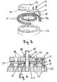
- FIG. 2 an inventive link plate 16 is shown, which is used for guiding and damping a ring valve.
- the handlebar plate has a central opening for the implementation of a central screw. Furthermore, it has a plurality of outer spring arms 17, which are preferably arranged distributed regularly over the circumference. In this figure, radially adjacent spring arms arranged on two concentric circles.
- the spring arms have at their ends guide tongues 18 and are out of the plane of the handlebar plate bent spring arms, better visible in FIG. 3 ,
- the guide tongues are preferably narrower, possibly also thinner areas of the spring arm, which are preferably bent out more than the rest of the spring arm. If only the spring tongue extends into a corresponding groove, then this can be made correspondingly narrow.
- the link plate has a further spring element, an inner link spring 19, on. This is referred to as a helical recess, e.g. Cutout, formed around the central opening around.
- the inner link spring takes over an axial steering of the link plate, in which a link plate is mounted axially fixed on the handlebar spring in the center, but can be deflected axially via the spring. Due to the fact that the handlebar plate does not take part in the central area, there is no friction in this area.
- the distances of the spring arms corresponding to the distances in corresponding grooves in sealing rings or in a sealing plate.
- FIG. 3 For the sake of clarity, a ring valve is only very schematic and certain components are only partially shown. Between the valve seat 33 and valve catch 32, two sealing rings 35 are arranged concentrically. The sealing rings have circumferential grooves 39. The curved in the direction of the sealing rings spring arms engage with the guide tongues in these grooves. The sealing rings are smoothly guided axially by this spring guide, radially fixed in position.
- the link plate is pressed against the sealing rings by a plurality of compression springs 31 distributed over the link plate, in the form of spiral springs.
- the guide tongues 18 engage in the grooves of the valve rings and take over the elastic guidance of the same.
- a guide is thus compliant and smooth in the valve lift direction. Transverse to the stroke direction is a guide through the outer spring arms and the inner arm spring firmly and essentially unyielding.
- damper plate 37 e.g. made of a plastic
- damper plate 37 e.g. made of a plastic
- the valve seat 33 has a plurality of inlet channels 43, the valve catcher 32 a plurality of outlet channels 44. Sealing on correspondingly tapered sealing surfaces of the inlet channels of the valve seat are sealing rings 35. Arranged above the handlebar plate 16 with the bent spring arms 17, which engage in the grooves of the sealing rings. On the handlebar plate resting pressure springs 31, which with its other end in Spring springs 34 are arranged in the valve catcher 32. Applied inside the valve on the catcher is a damping plate 37, preferably glued on, for additional damping of the valve.
- the valve is held by a central screw 48 and co-operating nut 40 and lock washer 49.
- the maximum stroke of the valve is given by spacers 47.1, 47.2. These can be connected separately, but also firmly with the valve seat or possibly also with the catcher.
- the handlebar plate is fastened to the inner link spring 19 on one or both spacers, preferably clamped therebetween.
- the link plate is thus axially and radially fixed in the central region, but axially 'steered' by the inner link spring.
- the link plate is not completely bent at a stroke accordingly, but axially deflected over the possible deflection of the inner link spring.
- the handlebar plate is positioned on the sealing ring, and the outer spring arms and the compression springs are tuned to each other so that the handlebar plate in an unloaded state, which corresponds to a closed valve, rests neither on the sealing rings nor on the catcher.
- This is preferably set at 50% of the valve lift.
- such a damping property can be set essentially as desired by tuning the spring constants of the two spring elements 17, 31.
- the embodiment is shown with reference to two concentrically arranged sealing rings and spring arms.
- a ring valve preferably 1-12, typically 4-20, e.g. 8 spring arms 17 arranged radially adjacent to each other.
- the materials used are metal and plastic, preferably glass or carbon fiber reinforced plastic.
- materials are selected for the individual valve parts, with which they achieve their optimal function.
- a valve seat and catcher, as well as the handlebar plate is preferably made of metal, the sealing rings a possible damping plate made of plastic.
- Other suitable materials are conceivable, such as ceramic sealing rings.
- the simple design also allows easy production, such as producing a one-piece spring plate.
- FIGS. 5a and 5b possible groove shapes for the engagement of one or more spring arms or their guide tongues are shown.
- a sealing ring 55 has a substantially circumferential groove 59.
- the groove is as elongated cutout 60 is formed, wherein a plurality of such cut-outs are preferably arranged distributed in a regular arrangement over the circumference of a sealing ring 55 '. If a sealing plate is used instead of sealing rings, these grooves or cut-outs are accordingly preferably placed concentrically in the sealing plate.
- Circumferential grooves and recesses can also be combined, for example circumferential grooves on an inner smaller sealing ring and cut-outs in the larger sealing rings.
- the groove widths are preferably matched exactly to corresponding spring arms or guide tongues on spring arms.
- a groove length is at least as large as a radial displacement of the ends of the spring arms or the guide tongues, which arises at a stroke of the valve.
Landscapes
- Engineering & Computer Science (AREA)
- General Engineering & Computer Science (AREA)
- Mechanical Engineering (AREA)
- Sealing Devices (AREA)
Applications Claiming Priority (1)
| Application Number | Priority Date | Filing Date | Title |
|---|---|---|---|
| CH6652009A CH700881B1 (de) | 2009-04-28 | 2009-04-28 | Ringventil. |
Publications (1)
| Publication Number | Publication Date |
|---|---|
| EP2249036A1 true EP2249036A1 (fr) | 2010-11-10 |
Family
ID=40873775
Family Applications (1)
| Application Number | Title | Priority Date | Filing Date |
|---|---|---|---|
| EP10405085A Withdrawn EP2249036A1 (fr) | 2009-04-28 | 2010-04-22 | Soupape annulaire |
Country Status (2)
| Country | Link |
|---|---|
| EP (1) | EP2249036A1 (fr) |
| CH (1) | CH700881B1 (fr) |
Cited By (3)
| Publication number | Priority date | Publication date | Assignee | Title |
|---|---|---|---|---|
| ITFI20120048A1 (it) * | 2012-03-08 | 2013-09-09 | Nuovo Pignone Srl | "automatic valve with a spring holder ring" |
| US20150075650A1 (en) * | 2013-09-04 | 2015-03-19 | Hoerbiger Kompressortechnik Holding Gmbh | Valve plate for gas exchange valves |
| CN111237168A (zh) * | 2020-02-26 | 2020-06-05 | 无锡康茨压缩机配件与系统有限公司 | 一种带有柔性同步片的压缩机气阀密封元件 |
Citations (8)
| Publication number | Priority date | Publication date | Assignee | Title |
|---|---|---|---|---|
| US1425613A (en) | 1919-09-18 | 1922-08-15 | Harold I Stage | Feeding means for drills |
| US1433094A (en) | 1921-03-31 | 1922-10-24 | Ingersoll Rand Co | Plate valve |
| GB251472A (en) | 1925-07-02 | 1926-05-06 | Ingersoll Rand Co | Valve |
| GB319498A (en) | 1928-09-28 | 1929-09-26 | Ingersoll Rand Co | Improvements in or relating to plate valves |
| DE1425613A1 (de) * | 1962-01-13 | 1969-03-20 | Dienes Werke | Ventil mit Lenkerplatte,die gleichzeitig als Belastungsfeder wirkt |
| EP0572748A1 (fr) | 1992-06-02 | 1993-12-08 | Maschinenfabrik Sulzer-Burckhardt AG | Soupape annulaire pour compresseur à piston |
| EP1939451A2 (fr) | 2006-12-22 | 2008-07-02 | Hoerbiger Kompressortechnik Holding GmbH | Soupape annulaire automatique |
| EP1939450A2 (fr) | 2006-12-22 | 2008-07-02 | Hoerbiger Kompressortechnik Holding GmbH | Soupape annulaire automatique |
-
2009
- 2009-04-28 CH CH6652009A patent/CH700881B1/de not_active IP Right Cessation
-
2010
- 2010-04-22 EP EP10405085A patent/EP2249036A1/fr not_active Withdrawn
Patent Citations (8)
| Publication number | Priority date | Publication date | Assignee | Title |
|---|---|---|---|---|
| US1425613A (en) | 1919-09-18 | 1922-08-15 | Harold I Stage | Feeding means for drills |
| US1433094A (en) | 1921-03-31 | 1922-10-24 | Ingersoll Rand Co | Plate valve |
| GB251472A (en) | 1925-07-02 | 1926-05-06 | Ingersoll Rand Co | Valve |
| GB319498A (en) | 1928-09-28 | 1929-09-26 | Ingersoll Rand Co | Improvements in or relating to plate valves |
| DE1425613A1 (de) * | 1962-01-13 | 1969-03-20 | Dienes Werke | Ventil mit Lenkerplatte,die gleichzeitig als Belastungsfeder wirkt |
| EP0572748A1 (fr) | 1992-06-02 | 1993-12-08 | Maschinenfabrik Sulzer-Burckhardt AG | Soupape annulaire pour compresseur à piston |
| EP1939451A2 (fr) | 2006-12-22 | 2008-07-02 | Hoerbiger Kompressortechnik Holding GmbH | Soupape annulaire automatique |
| EP1939450A2 (fr) | 2006-12-22 | 2008-07-02 | Hoerbiger Kompressortechnik Holding GmbH | Soupape annulaire automatique |
Cited By (8)
| Publication number | Priority date | Publication date | Assignee | Title |
|---|---|---|---|---|
| ITFI20120048A1 (it) * | 2012-03-08 | 2013-09-09 | Nuovo Pignone Srl | "automatic valve with a spring holder ring" |
| WO2013131976A1 (fr) * | 2012-03-08 | 2013-09-12 | Nuovo Pignone Srl | Soupape automatique avec un ressort anneau de support |
| US9765770B2 (en) | 2012-03-08 | 2017-09-19 | Nuovo Pignone Srl | Automatic valve with a spring holder ring |
| US20150075650A1 (en) * | 2013-09-04 | 2015-03-19 | Hoerbiger Kompressortechnik Holding Gmbh | Valve plate for gas exchange valves |
| CN104564615A (zh) * | 2013-09-04 | 2015-04-29 | 贺尔碧格压缩机技术控股有限公司 | 用于换气阀的阀板 |
| US9702353B2 (en) * | 2013-09-04 | 2017-07-11 | Hoerbiger Kompressortechnik Holding Gmbh | Valve plate for gas exchange valves |
| CN104564615B (zh) * | 2013-09-04 | 2018-04-10 | 贺尔碧格压缩机技术控股有限公司 | 用于换气阀的阀板 |
| CN111237168A (zh) * | 2020-02-26 | 2020-06-05 | 无锡康茨压缩机配件与系统有限公司 | 一种带有柔性同步片的压缩机气阀密封元件 |
Also Published As
| Publication number | Publication date |
|---|---|
| CH700881A1 (de) | 2010-10-29 |
| CH700881B1 (de) | 2013-12-13 |
Similar Documents
| Publication | Publication Date | Title |
|---|---|---|
| DE3431792C2 (de) | Faltenbalgvorrichtung | |
| EP1939451A2 (fr) | Soupape annulaire automatique | |
| DE102010064074B4 (de) | Stoßdämpfer | |
| EP3380743B1 (fr) | Amortisseur de vibrations à butée de traction hydraulique | |
| CH686457A5 (de) | Platten-Schieber. | |
| EP2581625A2 (fr) | Installation de ressort pneumatique ou amortisseur à ressort pneumatique avec commande de soupape intégrée | |
| EP3184863B1 (fr) | Soufflet a membrane | |
| WO2015097014A1 (fr) | Bague d'étanchéité | |
| EP2530365B2 (fr) | Garniture de soupape pour une armature sanitaire | |
| EP2249036A1 (fr) | Soupape annulaire | |
| DE102010008194A1 (de) | Adaptives Federelement | |
| EP4118365A1 (fr) | Ensemble segment de piston, compresseur à piston et procédé permettant de sceller une chambre de compression | |
| EP4229305A1 (fr) | Cylindre de travail à amortissement de position finale, et segment de piston d'amortissement | |
| DE68917629T2 (de) | Ventil für Fluide. | |
| EP1440633A2 (fr) | Colonne télescopique | |
| EP1917456B1 (fr) | Amortisseur de vibrations | |
| DE102010047140A1 (de) | Schaltgabel mit Gleitschuhen | |
| EP1487683A1 (fr) | Unite piston comportant un ressort bloque | |
| EP3580463B1 (fr) | Dispositif comportant un piston, un cylindre et au moins un tube intérieur et au moins un tube extérieur | |
| AT526786B1 (de) | Steckverbinder zum Verbinden einer ersten Fluidleitung mit einer zweiten Fluidleitung | |
| DE202020004388U1 (de) | Endlagengedämpfter Arbeitszylinder und Dämpfungskolbenring | |
| EP1466082B1 (fr) | Galet suiveur couplable ou element de support couplable d'un entrainement de soupape dans un moteur a combustion interne | |
| DE3100639C2 (de) | Absperr- und Regelorgan eines Dampfumformventiles | |
| EP3748191B1 (fr) | Commande optimisé de la longueur de chaîne | |
| DE19719291A1 (de) | Absperrvorrichtung |
Legal Events
| Date | Code | Title | Description |
|---|---|---|---|
| PUAI | Public reference made under article 153(3) epc to a published international application that has entered the european phase |
Free format text: ORIGINAL CODE: 0009012 |
|
| AK | Designated contracting states |
Kind code of ref document: A1 Designated state(s): AT BE BG CH CY CZ DE DK EE ES FI FR GB GR HR HU IE IS IT LI LT LU LV MC MK MT NL NO PL PT RO SE SI SK SM TR |
|
| AX | Request for extension of the european patent |
Extension state: AL BA ME RS |
|
| 17P | Request for examination filed |
Effective date: 20110211 |
|
| 17Q | First examination report despatched |
Effective date: 20160602 |
|
| STAA | Information on the status of an ep patent application or granted ep patent |
Free format text: STATUS: EXAMINATION IS IN PROGRESS |
|
| STAA | Information on the status of an ep patent application or granted ep patent |
Free format text: STATUS: THE APPLICATION IS DEEMED TO BE WITHDRAWN |
|
| 18D | Application deemed to be withdrawn |
Effective date: 20161013 |