EP2249037A2 - Procédé de fabrication d'un segment de stator de pompe à vis excentrique à stator segmenté - Google Patents
Procédé de fabrication d'un segment de stator de pompe à vis excentrique à stator segmenté Download PDFInfo
- Publication number
- EP2249037A2 EP2249037A2 EP10004334A EP10004334A EP2249037A2 EP 2249037 A2 EP2249037 A2 EP 2249037A2 EP 10004334 A EP10004334 A EP 10004334A EP 10004334 A EP10004334 A EP 10004334A EP 2249037 A2 EP2249037 A2 EP 2249037A2
- Authority
- EP
- European Patent Office
- Prior art keywords
- stator
- segment
- cutting means
- helical
- eccentric screw
- Prior art date
- Legal status (The legal status is an assumption and is not a legal conclusion. Google has not performed a legal analysis and makes no representation as to the accuracy of the status listed.)
- Withdrawn
Links
Images
Classifications
-
- F—MECHANICAL ENGINEERING; LIGHTING; HEATING; WEAPONS; BLASTING
- F04—POSITIVE - DISPLACEMENT MACHINES FOR LIQUIDS; PUMPS FOR LIQUIDS OR ELASTIC FLUIDS
- F04C—ROTARY-PISTON, OR OSCILLATING-PISTON, POSITIVE-DISPLACEMENT MACHINES FOR LIQUIDS; ROTARY-PISTON, OR OSCILLATING-PISTON, POSITIVE-DISPLACEMENT PUMPS
- F04C2/00—Rotary-piston machines or pumps
- F04C2/08—Rotary-piston machines or pumps of intermeshing-engagement type, i.e. with engagement of co-operating members similar to that of toothed gearing
- F04C2/10—Rotary-piston machines or pumps of intermeshing-engagement type, i.e. with engagement of co-operating members similar to that of toothed gearing of internal-axis type with the outer member having more teeth or tooth-equivalents, e.g. rollers, than the inner member
- F04C2/107—Rotary-piston machines or pumps of intermeshing-engagement type, i.e. with engagement of co-operating members similar to that of toothed gearing of internal-axis type with the outer member having more teeth or tooth-equivalents, e.g. rollers, than the inner member with helical teeth
- F04C2/1071—Rotary-piston machines or pumps of intermeshing-engagement type, i.e. with engagement of co-operating members similar to that of toothed gearing of internal-axis type with the outer member having more teeth or tooth-equivalents, e.g. rollers, than the inner member with helical teeth the inner and outer member having a different number of threads and one of the two being made of elastic materials, e.g. Moineau type
- F04C2/1073—Rotary-piston machines or pumps of intermeshing-engagement type, i.e. with engagement of co-operating members similar to that of toothed gearing of internal-axis type with the outer member having more teeth or tooth-equivalents, e.g. rollers, than the inner member with helical teeth the inner and outer member having a different number of threads and one of the two being made of elastic materials, e.g. Moineau type where one member is stationary while the other member rotates and orbits
- F04C2/1075—Construction of the stationary member
-
- F—MECHANICAL ENGINEERING; LIGHTING; HEATING; WEAPONS; BLASTING
- F04—POSITIVE - DISPLACEMENT MACHINES FOR LIQUIDS; PUMPS FOR LIQUIDS OR ELASTIC FLUIDS
- F04C—ROTARY-PISTON, OR OSCILLATING-PISTON, POSITIVE-DISPLACEMENT MACHINES FOR LIQUIDS; ROTARY-PISTON, OR OSCILLATING-PISTON, POSITIVE-DISPLACEMENT PUMPS
- F04C2230/00—Manufacture
- F04C2230/10—Manufacture by removing material
-
- F—MECHANICAL ENGINEERING; LIGHTING; HEATING; WEAPONS; BLASTING
- F04—POSITIVE - DISPLACEMENT MACHINES FOR LIQUIDS; PUMPS FOR LIQUIDS OR ELASTIC FLUIDS
- F04C—ROTARY-PISTON, OR OSCILLATING-PISTON, POSITIVE-DISPLACEMENT MACHINES FOR LIQUIDS; ROTARY-PISTON, OR OSCILLATING-PISTON, POSITIVE-DISPLACEMENT PUMPS
- F04C2240/00—Components
- F04C2240/70—Use of multiplicity of similar components; Modular construction
-
- Y—GENERAL TAGGING OF NEW TECHNOLOGICAL DEVELOPMENTS; GENERAL TAGGING OF CROSS-SECTIONAL TECHNOLOGIES SPANNING OVER SEVERAL SECTIONS OF THE IPC; TECHNICAL SUBJECTS COVERED BY FORMER USPC CROSS-REFERENCE ART COLLECTIONS [XRACs] AND DIGESTS
- Y10—TECHNICAL SUBJECTS COVERED BY FORMER USPC
- Y10T—TECHNICAL SUBJECTS COVERED BY FORMER US CLASSIFICATION
- Y10T29/00—Metal working
- Y10T29/49—Method of mechanical manufacture
- Y10T29/49229—Prime mover or fluid pump making
- Y10T29/49236—Fluid pump or compressor making
- Y10T29/49242—Screw or gear type, e.g., Moineau type
Definitions
- the invention relates to a method for producing a stator segment for a segmented stator of an eccentric screw pump or an eccentric screw motor, a stator segment and a stator.
- Eccentric screw pumps and eccentric screw motors which operate according to the Moineau principle are known in principle.
- Such pumps and motors usually comprise a stator and a rotor arranged in the interior of the stator.
- the stator comprises a stator tube made of a relatively hard material and an elastomeric lining connected to the inner surface of the stator tube.
- the lining is shaped in the manner of a multi-start, helical, steep thread and forms a cavity in which the rigid rotor, which is likewise shaped in the manner of a helical coarse thread, is accommodated, the rotor having one less gear than the stator.
- a stator for an eccentric screw pump or an eccentric screw motor which operate according to the Moineau principle discloses the US 7396220 B2 ,
- the stator comprises a plurality of stator segments arranged axially one behind the other.
- Each stator segment has a helical segment inner surface, wherein in the assembled state the individual segment inner surfaces of the stator segments complement one another to form a helical stator inner surface.
- the stator additionally comprises a lining made of an elastomer, which comprises the stator inner surface which is composed of the individual helical segment inner surfaces Layer thickness covered.
- the stator segments are connected in a material-locking manner to an outer tube surrounding the stator segments.
- stator segments The alignment of the stator segments with each other is ensured by pins which engage positively to prevent rotation of adjacent stator segments each in two adjacent stator segments.
- An alternative to fixing the individual stator segments provides that one or more grooves extending in the axial direction are formed in an outer tube surrounding the stator segments, in which the stator segments engage with projections in a form-fitting manner.
- a movement of the stator segments in the axial direction is secured by a front and rear screw.
- the individual stator segments are produced by a casting process.
- the material used is aluminum.
- a stator segment preferably has an axial extent of 150 to 600 mm.
- a disadvantage of the production of a stator segment by a casting method is that a new casting mold is necessary for each stator segment with a changed segment inner surface.
- the object of the present invention is to propose a variable method for producing a stator segment for a segmented stator of an eccentric screw pump or an eccentric screw motor, as well as a stator segment and a stator.
- a stator segment which is in an initial state is machined by means of a material-removing linear cutting means for producing a helical segment inner surface.
- the removal of the material by the cutting means can be done, for example, exciting, abrasive or evaporating.
- a linear cutting means is preferably a jet, for example, a water jet, a laser beam or a plasma jet, or a wire, for example, a fuse wire or a spark erosion wire used.
- helical preferably also includes surfaces approximating a helical shape.
- the alignment and the method of the cutting means is provided in an advantageous development such that the cutting means enters at a first outer edge of the helical segment inner surface to be produced and exits a second outer edge of the helical segment inner surface to be produced, the course of the cutting means of the helical segment inner surface to be produced, which is enclosed by the first outer edge and the second outer edge follows.
- the cutting means in this way along two closed lines, the first Outer edge and the second outer edge, proceed and thereby, if necessary, rotated and pivoted. A discontinuation of the cutting means is not necessary.
- stator segments produced in this way can be joined together to form a stator.
- the stator can be designed, for example, as a stator of an eccentric screw pump or an eccentric screw motor, which operate according to the Moineau principle.
- the helical inner surface of the stator composed of the individual segment inner surfaces of the stator segments is preferably covered with a lining of an elastomer, for example a rubber having a substantially uniform layer thickness.
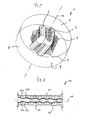
- FIG. 1 1 shows an embodiment of a stator segment 1 according to the invention for a segmented stator of an eccentric screw pump or an eccentric screw motor.
- the stator segment 1 is disc-shaped. It comprises a planar first base 6 oriented perpendicularly to a central axis 10 and a planar second aligned parallel to the first base 6 Base surface 7. Between the base surfaces 6, 7 there is a cylindrical lateral surface 8. The axial extent of the stator segment 1 is at most 100 mm.
- the stator segment 1 is made of metal, in this case made of aluminum. Alternatively, the stator segment 1, for example, also made of ceramic or a crosslinked or thermoplastic polymer.
- the stator segment 1 has a helical segment inner surface 2 surrounding the axis 10.
- the helical segment inner surface 2 is bounded by a first closed outer edge 3 and a second closed outer edge 4.
- the first outer edge 3 is inner edge of the first base 6, the second outer edge 4 inner edge of the second base 7.
- the segment inner surface 2 is formed such that it can be assembled from the first outer edge 3 to the second outer edge 4 extending straight line 5.
- a plurality of such lines 5 is shown by way of example.
- the helical segment inner surface 2 approximates an ideal helix shape.
- the deviation from the ideal shape due to the approach of straight lines extending from the first outer edge 3 to the second outer edge 4 depends in particular on the axial extent of the stator segment 1. By reducing the axial extent, the approach to the ideal helix shape can be improved.
- a stator segment which is in an initial state is processed by means of a material-removing beam for generating the helical segment inner surface 2.
- the stator segment which is not shown in the starting state, is a disk-shaped solid material having a flat first base surface and a second plane plane-parallel to the first base surface Base surface, as well as between the first base surface and the second base surface lying cylindrical lateral surface 8.
- the axial extent of the stator located in the initial state segment corresponds to the axial extent of the machined stator segment.
- stator in the initial state instead of a solid material, for example, have a hole or a hole.
- a segment inner piece with an inner piece outer surface complementary to the helical segment inner surface 2 is cut out of the stator segment in the initial state.
- the segment inner piece (not shown) is removed from the processed stator segment 1, for example by unscrewing or alternative measures known per se.
- the beam is aligned and moved such that the beam penetrates into the material on the first outer edge 3 of the helical segment inner surface 2 to be produced and leaves the material on the second outer edge 4 bounding the helical segment inner surface 2, the beam path of the generating helical segment inner surface 2 follows.
- the in the Fig. 1 In principle, it is possible in this way, exclusively by moving the beam along the first outer edge 3 and the second outer edge 4, the helical segment inner surface 2 form, which is preferred according to the invention.
- the jet does not have to be discontinued in this case. Furthermore, the mass of the material to be removed for cutting out the inner segment piece is minimized.
- a beam for removing the material as punctiform as possible water jet is used, to which an abrasive is added.
- Alternative blasting methods are also possible, for example a laser beam method or plasma cutting method.
- several beams can be used in parallel.
- the control of such a jet is carried out as follows:
- the aim is to produce a segment inner surface 2 which can be described by a helical screwing of a cross section corresponding to a hypocycloid or preferably an epihypocycloid.
- the beam is moved along the hypocycloid-shaped cross-sectional contour over the outer edge 3.
- a different beam direction vector can be assigned to each point on the segment inner surface 2 to be generated, and in this way the ideal helical shape can be approximated.
- the beam is preferably linearly moved both along two mutually linearly independent axes which lie in a plane oriented perpendicular to the axis 10 and rotated or pivoted about two axes of rotation perpendicular to one another in this plane.
- the control is preferably carried out automatically and computer-assisted.
- a linearly tensioned wire for example a spark erosion wire or a fusible wire
- the machining of the stator segment 1 for producing the segment inner surface 2 by means of spark erosion is suitable, for example, in the case of a stator segment 1 made of metal, by means of melting, for example, in the case of a stator segment 1 made of plastic.
- the Fig. 2 shows a longitudinal section through a portion of an embodiment of a segmented stator 20 according to the invention.
- the stator 20 comprises a plurality of stator segments 21 a, 21 b, which are arranged along the axis 10 axially one behind the other to form a helical stator inner surface 23.
- a single stator segment 21 a, 21 b is basically like that in Fig. 1 illustrated stator segment 1 is formed.
- the segment inner surface 2 varies from stator segment to stator segment in order to complement the helical stator inner surface 23.
- the stator 20 comprises an outer tube 24.
- the stator 21 a, 21 b are disposed within the outer tube 24 and relative to a movement in the axial direction and against the execution of a rotary motion relative secured to adjacent stator segments, for example by material or positive connection.
- Such measures are known per se. In this regard, the disclosure of the US 7396220 B2 directed.
- a fixation of the stator 21 a, 21 b by compression of the outer tube 24 is possible.
- the outer tube 24 is radially compressed until a sufficient fixation of the stator 21 a, 21 b is given.
- the stator 20 additionally comprises a lining 25 made of an elastomer, here a rubber, which is supported by the individual stator segments 21 a, 21 b formed helical Statorinnen Chemistry 23 is applied.
- the liner 25 has a substantially uniform thickness.
Landscapes
- Engineering & Computer Science (AREA)
- Mechanical Engineering (AREA)
- General Engineering & Computer Science (AREA)
- Rotary Pumps (AREA)
- Details And Applications Of Rotary Liquid Pumps (AREA)
Applications Claiming Priority (1)
| Application Number | Priority Date | Filing Date | Title |
|---|---|---|---|
| US12/435,838 US20100284842A1 (en) | 2009-05-05 | 2009-05-05 | Method of producing a stator segment for a segmented stator of an eccentric screw pump |
Publications (1)
| Publication Number | Publication Date |
|---|---|
| EP2249037A2 true EP2249037A2 (fr) | 2010-11-10 |
Family
ID=42313137
Family Applications (1)
| Application Number | Title | Priority Date | Filing Date |
|---|---|---|---|
| EP10004334A Withdrawn EP2249037A2 (fr) | 2009-05-05 | 2010-04-23 | Procédé de fabrication d'un segment de stator de pompe à vis excentrique à stator segmenté |
Country Status (3)
| Country | Link |
|---|---|
| US (1) | US20100284842A1 (fr) |
| EP (1) | EP2249037A2 (fr) |
| CA (1) | CA2703059A1 (fr) |
Cited By (1)
| Publication number | Priority date | Publication date | Assignee | Title |
|---|---|---|---|---|
| DE202016100894U1 (de) | 2016-02-19 | 2016-03-02 | Artemis Kautschuk- Und Kunststoff-Technik Gmbh | Stator und/oder Rotor einer Exzenterschneckenpumpe oder eines Exzenterschneckenmotors |
Families Citing this family (9)
| Publication number | Priority date | Publication date | Assignee | Title |
|---|---|---|---|---|
| CN102139440B (zh) * | 2011-04-13 | 2013-01-23 | 时敬龙 | 稠油热采用全金属螺杆泵定子的加工方法 |
| US8967985B2 (en) * | 2012-11-13 | 2015-03-03 | Roper Pump Company | Metal disk stacked stator with circular rigid support rings |
| US9133841B2 (en) * | 2013-04-11 | 2015-09-15 | Cameron International Corporation | Progressing cavity stator with metal plates having apertures with englarged ends |
| US9995085B2 (en) * | 2013-09-19 | 2018-06-12 | Balthazar L. Perez | Downhole motor stator and method of manufacture |
| US9850897B2 (en) | 2013-12-30 | 2017-12-26 | Cameron International Corporation | Progressing cavity stator with gas breakout port |
| EP3382203B1 (fr) * | 2017-03-30 | 2024-05-15 | Roper Pump Company LLC | Pompe à cavité progressive avec gaine de chauffage intégrée |
| CN109538112B (zh) * | 2019-01-04 | 2023-09-08 | 中国地质大学(北京) | 一种套装拼接式全金属螺杆定子加工方法 |
| CN109915044B (zh) * | 2019-03-22 | 2023-11-21 | 中国地质大学(北京) | 一种装配式螺杆钻具金属定子轴向加工装配工艺 |
| US20240247655A1 (en) * | 2023-01-20 | 2024-07-25 | Roper Pump Company Llc | Modular stator for progressive cavity devices |
Citations (1)
| Publication number | Priority date | Publication date | Assignee | Title |
|---|---|---|---|---|
| US7396220B2 (en) | 2005-02-11 | 2008-07-08 | Dyna-Drill Technologies, Inc. | Progressing cavity stator including at least one cast longitudinal section |
Family Cites Families (4)
| Publication number | Priority date | Publication date | Assignee | Title |
|---|---|---|---|---|
| US5832604A (en) * | 1995-09-08 | 1998-11-10 | Hydro-Drill, Inc. | Method of manufacturing segmented stators for helical gear pumps and motors |
| US7150101B2 (en) * | 2003-12-15 | 2006-12-19 | General Electric Company | Apparatus for fabricating components |
| US7941906B2 (en) * | 2007-12-31 | 2011-05-17 | Schlumberger Technology Corporation | Progressive cavity apparatus with transducer and methods of forming and use |
| US20090320285A1 (en) * | 2008-06-30 | 2009-12-31 | Tahany Ibrahim El-Wardany | Edm machining and method to manufacture a curved rotor blade retention slot |
-
2009
- 2009-05-05 US US12/435,838 patent/US20100284842A1/en not_active Abandoned
-
2010
- 2010-04-23 EP EP10004334A patent/EP2249037A2/fr not_active Withdrawn
- 2010-05-04 CA CA2703059A patent/CA2703059A1/fr not_active Abandoned
Patent Citations (1)
| Publication number | Priority date | Publication date | Assignee | Title |
|---|---|---|---|---|
| US7396220B2 (en) | 2005-02-11 | 2008-07-08 | Dyna-Drill Technologies, Inc. | Progressing cavity stator including at least one cast longitudinal section |
Cited By (1)
| Publication number | Priority date | Publication date | Assignee | Title |
|---|---|---|---|---|
| DE202016100894U1 (de) | 2016-02-19 | 2016-03-02 | Artemis Kautschuk- Und Kunststoff-Technik Gmbh | Stator und/oder Rotor einer Exzenterschneckenpumpe oder eines Exzenterschneckenmotors |
Also Published As
| Publication number | Publication date |
|---|---|
| US20100284842A1 (en) | 2010-11-11 |
| CA2703059A1 (fr) | 2010-11-05 |
Similar Documents
| Publication | Publication Date | Title |
|---|---|---|
| EP2249037A2 (fr) | Procédé de fabrication d'un segment de stator de pompe à vis excentrique à stator segmenté | |
| DE69323092T2 (de) | Methode und werkzeug zum herstellen von löchern in fiberverstärkten kompositen durch exzentrische bewegung des werkzeugs | |
| EP2659158B1 (fr) | Disque de frein et procédé servant à traiter la surface d'un disque de frein | |
| EP2256345A2 (fr) | Stator pour une pompe à vis excentrique ou un moteur à vis excentrique et procédé de fabrication d'un stator | |
| DE102011055210A1 (de) | Werkzeug zur Gewindeherstellung | |
| DE10245197A1 (de) | Verfahren und Vorrichtung zum Herstellen von Gabelfüßen von Turbinenschaufeln | |
| DE102017107999A1 (de) | Entgratvorrichtung sowie CNC-Verzahnmaschine mit einer solchen Entgratvorrichtung | |
| WO2019228945A1 (fr) | Outil d'épluchage à rouleaux | |
| WO2020208114A1 (fr) | Outil de fraisage permettant le fraisage de pièces | |
| DE102008030100B4 (de) | Gewindefräser | |
| EP3427880B1 (fr) | Méthode de fabrication d'un rotor pour une pompe à vis; machine d'usinage par enlèvement de copeaux à cet effet | |
| EP1967307B1 (fr) | Procédé de fabrication d'un élément de moyeu de rotor pourvu de rainures | |
| DE102013002730A1 (de) | Fräswerkzeug zum Schruppen und Schlichten von Werkstücken | |
| EP1784282B1 (fr) | Meule pour produire des filetages a billes males ou femelles sur des pieces a usiner | |
| EP2180967B1 (fr) | Procédé pour fabriquer un corps de machine comportant une chambre de fluide à surface durcie | |
| EP1455979A1 (fr) | Procede et outil servant a la fabrication d'une piece interne d'un joint homocinetique | |
| EP2509746B1 (fr) | Dispositif pour meuler des électrodes et meule | |
| EP3085492B1 (fr) | Outil de rectification | |
| EP3027383B1 (fr) | Procédé servant à fabriquer un cylindre à double vis pourvu d'une couche de protection contre l'usure | |
| WO2012089377A1 (fr) | Outil de coupe pour produire au moins une dépression dans une surface, en particulier dans la surface d'un disque de frein | |
| DE19948891A1 (de) | Gedämpftes Werkzeug | |
| DE102016215910B3 (de) | Spindelmutter | |
| DE102018118213A1 (de) | Verfahren zur Herstellung einer Außenverzahnung einer Kupplungsscheibe, Schneidwerkzeug zur Verwendung in einem Zykloidenfräser und Kupplungsscheibe | |
| WO2004041464A1 (fr) | Outil de coupe de filets | |
| DE102017011276A1 (de) | Verfahren zum Herstellen eines Zahnrads |
Legal Events
| Date | Code | Title | Description |
|---|---|---|---|
| PUAI | Public reference made under article 153(3) epc to a published international application that has entered the european phase |
Free format text: ORIGINAL CODE: 0009012 |
|
| AK | Designated contracting states |
Kind code of ref document: A2 Designated state(s): AT BE BG CH CY CZ DE DK EE ES FI FR GB GR HR HU IE IS IT LI LT LU LV MC MK MT NL NO PL PT RO SE SI SK SM TR |
|
| AX | Request for extension of the european patent |
Extension state: AL BA ME RS |
|
| STAA | Information on the status of an ep patent application or granted ep patent |
Free format text: STATUS: THE APPLICATION IS DEEMED TO BE WITHDRAWN |
|
| 18D | Application deemed to be withdrawn |
Effective date: 20131101 |