EP2249038A2 - Machine à engrenage externe dotée d'un palier pour l'axe simplifié - Google Patents
Machine à engrenage externe dotée d'un palier pour l'axe simplifié Download PDFInfo
- Publication number
- EP2249038A2 EP2249038A2 EP10161300A EP10161300A EP2249038A2 EP 2249038 A2 EP2249038 A2 EP 2249038A2 EP 10161300 A EP10161300 A EP 10161300A EP 10161300 A EP10161300 A EP 10161300A EP 2249038 A2 EP2249038 A2 EP 2249038A2
- Authority
- EP
- European Patent Office
- Prior art keywords
- bearing
- rotor
- fluid
- piston
- profile
- Prior art date
- Legal status (The legal status is an assumption and is not a legal conclusion. Google has not performed a legal analysis and makes no representation as to the accuracy of the status listed.)
- Withdrawn
Links
- 239000012530 fluid Substances 0.000 claims abstract description 97
- 238000006073 displacement reaction Methods 0.000 claims abstract description 43
- 230000004323 axial length Effects 0.000 claims abstract description 14
- 239000000314 lubricant Substances 0.000 claims description 67
- 238000007789 sealing Methods 0.000 claims description 36
- 238000004140 cleaning Methods 0.000 claims description 20
- 230000003134 recirculating effect Effects 0.000 claims description 7
- 239000010687 lubricating oil Substances 0.000 claims description 5
- 238000003860 storage Methods 0.000 abstract description 5
- 238000005461 lubrication Methods 0.000 description 13
- 238000009826 distribution Methods 0.000 description 9
- 238000001816 cooling Methods 0.000 description 7
- 238000005304 joining Methods 0.000 description 7
- 239000013585 weight reducing agent Substances 0.000 description 6
- 238000004519 manufacturing process Methods 0.000 description 5
- 239000002245 particle Substances 0.000 description 4
- 238000002485 combustion reaction Methods 0.000 description 3
- 230000018109 developmental process Effects 0.000 description 3
- 230000013011 mating Effects 0.000 description 3
- 230000008901 benefit Effects 0.000 description 2
- 239000010779 crude oil Substances 0.000 description 2
- 230000002349 favourable effect Effects 0.000 description 2
- 230000001050 lubricating effect Effects 0.000 description 2
- 230000002093 peripheral effect Effects 0.000 description 2
- 230000009467 reduction Effects 0.000 description 2
- 238000005096 rolling process Methods 0.000 description 2
- 238000005299 abrasion Methods 0.000 description 1
- 238000010521 absorption reaction Methods 0.000 description 1
- 230000009286 beneficial effect Effects 0.000 description 1
- 230000005540 biological transmission Effects 0.000 description 1
- 230000015572 biosynthetic process Effects 0.000 description 1
- 230000008859 change Effects 0.000 description 1
- 238000010276 construction Methods 0.000 description 1
- 239000000356 contaminant Substances 0.000 description 1
- 230000000694 effects Effects 0.000 description 1
- 238000003754 machining Methods 0.000 description 1
- 238000000034 method Methods 0.000 description 1
- 230000004048 modification Effects 0.000 description 1
- 238000012986 modification Methods 0.000 description 1
- 239000003921 oil Substances 0.000 description 1
- 238000003825 pressing Methods 0.000 description 1
- 230000008569 process Effects 0.000 description 1
- 230000004044 response Effects 0.000 description 1
- 230000002000 scavenging effect Effects 0.000 description 1
- 230000001953 sensory effect Effects 0.000 description 1
- 238000007493 shaping process Methods 0.000 description 1
- 239000007787 solid Substances 0.000 description 1
- 238000009827 uniform distribution Methods 0.000 description 1
- 238000011144 upstream manufacturing Methods 0.000 description 1
Images

Classifications
-
- F—MECHANICAL ENGINEERING; LIGHTING; HEATING; WEAPONS; BLASTING
- F04—POSITIVE - DISPLACEMENT MACHINES FOR LIQUIDS; PUMPS FOR LIQUIDS OR ELASTIC FLUIDS
- F04C—ROTARY-PISTON, OR OSCILLATING-PISTON, POSITIVE-DISPLACEMENT MACHINES FOR LIQUIDS; ROTARY-PISTON, OR OSCILLATING-PISTON, POSITIVE-DISPLACEMENT PUMPS
- F04C15/00—Component parts, details or accessories of machines, pumps or pumping installations, not provided for in groups F04C2/00 - F04C14/00
- F04C15/0057—Driving elements, brakes, couplings, transmission specially adapted for machines or pumps
- F04C15/0061—Means for transmitting movement from the prime mover to driven parts of the pump, e.g. clutches, couplings, transmissions
- F04C15/0073—Couplings between rotors and input or output shafts acting by interengaging or mating parts, i.e. positive coupling of rotor and shaft
-
- F—MECHANICAL ENGINEERING; LIGHTING; HEATING; WEAPONS; BLASTING
- F01—MACHINES OR ENGINES IN GENERAL; ENGINE PLANTS IN GENERAL; STEAM ENGINES
- F01C—ROTARY-PISTON OR OSCILLATING-PISTON MACHINES OR ENGINES
- F01C21/00—Component parts, details or accessories not provided for in groups F01C1/00 - F01C20/00
- F01C21/02—Arrangements of bearings
-
- F—MECHANICAL ENGINEERING; LIGHTING; HEATING; WEAPONS; BLASTING
- F04—POSITIVE - DISPLACEMENT MACHINES FOR LIQUIDS; PUMPS FOR LIQUIDS OR ELASTIC FLUIDS
- F04C—ROTARY-PISTON, OR OSCILLATING-PISTON, POSITIVE-DISPLACEMENT MACHINES FOR LIQUIDS; ROTARY-PISTON, OR OSCILLATING-PISTON, POSITIVE-DISPLACEMENT PUMPS
- F04C15/00—Component parts, details or accessories of machines, pumps or pumping installations, not provided for in groups F04C2/00 - F04C14/00
- F04C15/0057—Driving elements, brakes, couplings, transmission specially adapted for machines or pumps
- F04C15/0076—Fixing rotors on shafts, e.g. by clamping together hub and shaft
-
- F—MECHANICAL ENGINEERING; LIGHTING; HEATING; WEAPONS; BLASTING
- F04—POSITIVE - DISPLACEMENT MACHINES FOR LIQUIDS; PUMPS FOR LIQUIDS OR ELASTIC FLUIDS
- F04C—ROTARY-PISTON, OR OSCILLATING-PISTON, POSITIVE-DISPLACEMENT MACHINES FOR LIQUIDS; ROTARY-PISTON, OR OSCILLATING-PISTON, POSITIVE-DISPLACEMENT PUMPS
- F04C15/00—Component parts, details or accessories of machines, pumps or pumping installations, not provided for in groups F04C2/00 - F04C14/00
- F04C15/0088—Lubrication
- F04C15/0092—Control systems for the circulation of the lubricant
-
- F—MECHANICAL ENGINEERING; LIGHTING; HEATING; WEAPONS; BLASTING
- F04—POSITIVE - DISPLACEMENT MACHINES FOR LIQUIDS; PUMPS FOR LIQUIDS OR ELASTIC FLUIDS
- F04C—ROTARY-PISTON, OR OSCILLATING-PISTON, POSITIVE-DISPLACEMENT MACHINES FOR LIQUIDS; ROTARY-PISTON, OR OSCILLATING-PISTON, POSITIVE-DISPLACEMENT PUMPS
- F04C2/00—Rotary-piston machines or pumps
- F04C2/08—Rotary-piston machines or pumps of intermeshing-engagement type, i.e. with engagement of co-operating members similar to that of toothed gearing
- F04C2/12—Rotary-piston machines or pumps of intermeshing-engagement type, i.e. with engagement of co-operating members similar to that of toothed gearing of other than internal-axis type
- F04C2/14—Rotary-piston machines or pumps of intermeshing-engagement type, i.e. with engagement of co-operating members similar to that of toothed gearing of other than internal-axis type with toothed rotary pistons
- F04C2/18—Rotary-piston machines or pumps of intermeshing-engagement type, i.e. with engagement of co-operating members similar to that of toothed gearing of other than internal-axis type with toothed rotary pistons with similar tooth forms
-
- F—MECHANICAL ENGINEERING; LIGHTING; HEATING; WEAPONS; BLASTING
- F04—POSITIVE - DISPLACEMENT MACHINES FOR LIQUIDS; PUMPS FOR LIQUIDS OR ELASTIC FLUIDS
- F04C—ROTARY-PISTON, OR OSCILLATING-PISTON, POSITIVE-DISPLACEMENT MACHINES FOR LIQUIDS; ROTARY-PISTON, OR OSCILLATING-PISTON, POSITIVE-DISPLACEMENT PUMPS
- F04C2240/00—Components
- F04C2240/50—Bearings
- F04C2240/52—Bearings for assemblies with supports on both sides
-
- F—MECHANICAL ENGINEERING; LIGHTING; HEATING; WEAPONS; BLASTING
- F04—POSITIVE - DISPLACEMENT MACHINES FOR LIQUIDS; PUMPS FOR LIQUIDS OR ELASTIC FLUIDS
- F04C—ROTARY-PISTON, OR OSCILLATING-PISTON, POSITIVE-DISPLACEMENT MACHINES FOR LIQUIDS; ROTARY-PISTON, OR OSCILLATING-PISTON, POSITIVE-DISPLACEMENT PUMPS
- F04C2240/00—Components
- F04C2240/60—Shafts
Definitions
- the invention relates to a rotary displacement machine with a bearing profile which forms a bearing shaft or bearing shaft for a rotor of the rotary displacement machine.
- the rotary displacement machine may be a motor or, in particular, a pump.
- Recirculating displacement machines include one or more rotatably mounted rotors which form or form cells around one or more axes of rotation in which fluid is transported from an inlet to an outlet of a chamber of the machine.
- the rotor or one of the rotors is mounted axially movable back and forth, as is known in particular from external gear pumps, for example from the DE 102 22 131 B4 .
- the rotor is part of an adjustment, which has a piston beyond the rotor and a bearing profile for the rotary mounting of the rotor.
- the piston is arranged axially facing a front side of the rotor.
- the bearing profile is usually fixedly connected to the piston and has a bearing surface about which the rotor is rotatable.
- the adjusting unit comprises a further piston, which faces the other end face of the rotor axially and is also firmly connected to the bearing profile.
- the bearing profile has a bearing portion with the bearing surface and left and right next to the bearing portion depending on a joint portion for the firm connection with the piston.
- the bearing portion is thicker than the joining portions to form a stop surface for the pistons in the axial direction.
- the bearing profile is formed from full rod semi-finished by means of machining. The production of the bearing profile therefore requires a lot of time and drives the costs, which is unfavorable for mass production.
- the invention is based on a recirculating displacement machine comprising a housing with a chamber and at least one rotor accommodated in the chamber.
- the chamber has an inlet and an outlet for a fluid to be conveyed or used as a drive medium.
- the rotor is rotatably supported for conveying the fluid or for driving by the fluid about an axis of rotation. It forms with walls of the chamber, and preferably in conveying engagement with another rotor, cells which revolve around the axis of rotation and in which the fluid is transported from the inlet to the outlet when the rotor is in the case of engine operation of the fluid or in the preferred case a pump operation is driven by means of external energy.
- the circulation displacement machine has an adjusting unit, which is axially reciprocable in the housing and is mounted so as to be secured against rotation in relation to the axis of rotation of the rotor.
- the adjusting unit comprises the rotor, at least one piston and a bearing profile.
- the components are connected with each other in such a way that they execute axial movements together and form a movement unit in this sense.
- the piston faces an axial end of the rotor and forms with the rotor an axial sealing gap which fluidly separates a high pressure side of the chamber from a low pressure side of the chamber except for unavoidable leakage.
- the bearing profile protrudes in the axial direction in the piston and the rotor. It can project through the piston or protrude into a cavity of the piston, which ends within the piston.
- the rotor is preferably penetrated by the bearing profile.
- the bearing profile forms around the axis of rotation a bearing surface for the rotary mounting of the rotor.
- the bearing surface forms with a bearing counter surface a bearing gap of the rotary bearing, ie, the bearing surface and the bearing surface limit the bearing gap in respect of the axis of rotation radial direction.
- the bearing surface is an outer peripheral surface of the bearing profile and the bearing surface surrounds the bearing surface.
- the bearing surface may surround the bearing surface.
- the bearing counter surface is of the Piston or preferably formed by the rotor.
- the bearing profile may be formed as an axis about which the rotor is rotatable, or as a shaft rotating together with the rotor.
- the rotor and the bearing profile can be connected to each other secured against rotation. If, as preferred, the rotor forms the counter bearing surface, the rotor accordingly rotates around the bearing profile to form the bearing gap.
- the bearing profile is preferably fixed, ie immovable, connected to the piston, preferably by means of a positive or frictional connection.
- the word "or” has the usual meaning of "and / or” here as well as otherwise in the sense of the invention, as far as nothing else can be deduced from the respective context.
- a cohesive connection is also possible, although not preferred.
- rolling elements can be arranged and the pivot bearing be formed as a rolling bearing. In preferred simple embodiments, however, the pivot bearing is designed as a sliding bearing.
- the bearing profile over its entire axial length or at least over almost the entire axial length of the bearing surface corresponding outer circumference.
- the joint section thus has the same outer contour as the bearing section.
- the two axial sections continuously merge.
- the bearing profile forms a joint section for each of the pistons, of which the one on the left and the other is located to the right of the bearing section.
- all three sections have the same outer contour, and the bearing section merges continuously on both sides into the respective joint section.
- the bearing profile corresponding to a joint portion for the torsionally rigid connection with the feed wheel and left and right of the joint section per a bearing portion with a Storage area for the pivot bearing formed with the piston. Accordingly, the bearing sections and the joining section have the same outer contour and merge continuously into one another.
- the bearing profile may comprise one or more interlocking elements in the or each of several joining sections, for example one or more flats, around the bearing profile with either the piston or pistons the rotor locked to connect.
- a press connection preferably a purely frictional connection, is preferred.
- the bearing profile can be ground to its nominal size via its surface which is shaped simply according to the invention, preferably over its entire outer surface, in a simple continuous grinding process, which leads to a considerable reduction in manufacturing costs and production time compared to conventionally shaped bearing profiles with radially offset sections.
- the bearing profile is at least partially hollow in preferred embodiments.
- the hollow cross-section preferably extends over the majority of the axial length of the bearing profile, advantageously over the entire or almost the entire axial length.
- the hollow cross section is preferably circular cylindrical inside.
- the cavity of the bearing profile preferably corresponds to at least half of the total volume of the bearing profile.
- the bearing profile may in particular be sleeve-shaped. It may have a bottom at one axial end.
- the hollow cross-section may extend continuously from the bottom to the other axial end of the bearing profile.
- the floor can basically be arranged between the ends instead of at one end.
- the bearing profile may be a simple sleeve with an axially constant throughout the same hollow cross-section.
- the bearing profile can thus be provided from one side with a bore or, for example, be formed simple tube.
- the formation of the bearing profile at least in sections as a hollow profile contributes to the weight reduction of the rotary displacement machine and in particular to the weight reduction of the adjustment at.
- the reduction of the moment of inertia associated with the weight reduction improves the response time of the adjustment unit.
- the rotary bearing of the rotor is preferably lubricated with the fluid to be pumped or used as the drive medium.
- the fluid in the chamber can be used, the so-called crude fluid. More preferably, however, a clean fluid is used which contains less contaminant compared to the crude fluid.
- the pump comprises a lubricant channel, through which a lubricant can be conveyed into the bearing gap.
- the lubricant channel extends from outside the chamber into the bearing gap to the fluid serving as a lubricant not from the chamber, but in the case of a pump from a point downstream and in the case of a motor, preferably upstream of the chamber as a lubricant in the bearing gap respectively.
- the fluid flow of Umlaufverdrängerkaschine From the fluid flow of Umlaufverdrängerkaschine a partial flow is diverted and performed for the purpose of bearing lubrication in the bearing gap.
- the lubrication concept begins with the knowledge that the fluid conveyed through the chamber can contain dirt particles, in particular wear particles, which increase the abrasion in the pivot bearing and therefore increase the wear of the pivot bearing, which can lead to seizure. Due to the approach from outside the chamber, the fluid for lubrication can be freed of dirt particles before being introduced into the bearing gap.
- the raw fluid is passed in preferred embodiments through a cleaning device, which is arranged in the case of a pump in a fluid circuit of the pump downstream of the pump.
- the purified by means of the cleaning device fluid ie the clean fluid is recycled in a return to the pump.
- the recirculation or, in the general case, the scavenging port is connected to the lubricant passage via a port formed on the housing of the recirculating displacement machine.
- the cleaning device or an additional cleaning device can also be arranged in the lubricant supply.
- the cleaning device or the additional cleaning device can also be arranged in the housing of the rotary displacement machine or directly on the housing.
- the fluid displaced in the case of a pump through the outlet of the chamber is branched into a first partial flow and a second partial flow, wherein the first partial flow, which preferably forms a main flow, is supplied wholly or partly to an aggregate to be supplied with the fluid and the second Partial flow is passed completely or in part through the cleaning device back into the lubricant channel.
- the cleaning device is arranged in or directly on the housing of the rotary displacement machine, it is advantageously arranged interchangeably.
- the cleaning device may be in all arrangement variants in particular a fluid filter with a single or multiple screens.
- Pure fluid lubrication also has the advantage that cooler pure fluid can be used to remove heat from the rotary bearing as compared to the crude fluid in the chamber.
- the crude fluid delivered by the pump is cooled on the high pressure side in the flow path to or preferably before the purifier by means of a cooler and returned to the pump as a lubricant in the cooled state. Therefore, if the cooling device is located downstream of the cleaning device, the return preferably branches off behind the cooling device.
- a cooling device can also be provided exclusively for the branched lubricant or additionally in the return, as also applies with respect to the cleaning device.
- the adjusting unit is preferably adjusted or positioned as a function of a fluid pressure of the high-pressure side. It is acted upon by the fluid pressure in a first direction of its mobility, so that the specific delivery volume is reduced with increasing pressure.
- the fluid pressure counteracts a restoring force.
- the adjusting unit is acted upon counteracting the fluid pressure with a spring force.
- the position of the adjusting unit adjusts itself to the current equilibrium of the adjusting force generated by means of the fluid pressure and the restoring force.
- the piston is exposed to the clean fluid.
- Such an embodiment allows the supply of the clean fluid through the piston into the bearing gap of the pivot bearing.
- Such an arrangement of the lubricant channel is structurally simple and guarantees a bearing lubrication with always sufficient pressure. If the bearing profile has a bottom, this bottom can form part of the piston surface acted on by the pressure fluid.
- the piston has an axial passage into which the bearing profile protrudes or projects. The passage preferably has the same cross-section everywhere and may in particular be formed as a circular through-bore. In other preferred embodiments, however, the piston has a sack-receiving space for the joining portion of the bearing profile.
- the adjustment can also be adjusted by motor, for example by means of an electric motor or a hydraulic positioning.
- a fluid pressure of the high pressure side can be used as a control variable
- a fluid temperature can be used as a control variable
- a flow or other physical size for example, a relevant for the needs of the unit to be supplied size, such as the engine speed, sensory detected and the position of the adjustment by a target-IstVer Eisen the controlled variable with a target size can be set.
- the lubricant While in conventional lubrication concepts using the raw fluid from the pump chamber as a lubricant, the lubricant is pressed with respect to the rotation axis from radially outside and thus against the centrifugal force in the bearing gap, namely simply from the high pressure side of the chamber, the lubricant is preferably Pure fluid, pressed in preferred embodiments of radially inward or at least on a same with the bearing gap radial height in the bearing gap. The centrifugal force thus supports the lubricant flow in the bearing gap or at least does not counteract this during the introduction into the bearing gap. However, the centrifugal force is preferably used for the discharge by the lubricant is discharged from the bearing gap radially outward to the low pressure side.
- the lubricant channel extends through the bearing profile and the bearing gap is preferably supplied from the inside radially with the lubricant.
- the bearing profile 1, in such embodiments, at least in sections, a hollow cross-section, which forms a portion of Sclamierstoffkanals.
- a connecting channel is formed, which from the hollow cross-section through the Bearing profile leads through to the outside to the storage area.
- the connecting channel may in particular be a simple radial bore in the bearing profile.
- the lubricant channel thus leads through the piston of the adjustment in the hollow cross section of the bearing profile. If the bearing profile has a bottom, the lubricant channel expediently leads through the bottom into the hollow cross section.
- the lubricant channel opens into an axially middle section of the bearing gap.
- the lubricant is distributed from the mouth region axially to both sides and therefore on a short path to the axial ends of the bearing gap.
- the bearing gap is connected at both axial ends to the low-pressure side of the rotary displacement machine, preferably the low-pressure side of the chamber, in order to remove the lubricant and in this way to ensure the flow through the bearing gap.
- the removal is preferably carried out by discharge channels, which are formed in sealing surfaces which face the two axial end faces of the rotor and each form an axial sealing gap with one of these sealing surfaces.
- the discharge channels are each formed in the sealing surfaces as a recess leading from the inside to the outside radially.
- the discharge channels are so narrow that they do not appreciably affect the sealing effect of the respective sealing gap.
- the lubricant would be introduced in such an embodiment conveniently at the opposite end of the discharge axial end of the bearing gap.
- the piston of the adjusting unit forms at least one of the two sealing surfaces. If the adjustment unit preferably has a piston arranged on the left and on the right of the rotor, each of the pistons forms one of the sealing surfaces.
- the guided through the bearing profile lubricant channel opens in a recess which is formed in the bearing surface or the counter bearing surface and extending in the circumferential direction about the axis of rotation of the rotor.
- the recess extends circumferentially about the axis of rotation, ie over 360 °.
- the bearing profile is a hollow shaft around which rotates the rotor, or a hollow shaft, which is rigidly connected to the rotor, it is advantageous if the recess is formed in the bearing counter-surface, so as not to weaken the shell of the hollow shaft or hollow shaft.
- the recess may instead or optionally additionally a recess in the hollow axle or shaft may be formed.
- the recess serves as a distribution channel for the lubricant. Without such a distribution channel, the lubricant channel would have to open in a non-rotatable bearing profile in the bearing gap in a rotational angular position in the operating load under a sufficiently wide gap for the distribution of the lubricant remains. Viewed over the circumference of the bearing surface, the forces in the operation of the rotary displacement machine namely are distributed nonuniformly.
- a distribution channel which extends in the circumferential direction over a sufficiently large rotation angle range, preferably over 360 °, allows the positioning of the mouth of the lubricant channel in the region of the recess at an arbitrary rotational angular position.
- the lubricant channel can also run on the bearing profile outside by the bearing profile in the region of its bearing surface has an axial or spiral circumferential recess or flattening, in which the lubricant is guided in the bearing gap and distributed in the axial direction.
- the lubricant channel would initially run on its feed side through said piston or non-adjustable rotor through a fixed chamber wall and axially bridging the sealing gap on the relevant end face of the rotor lead in the formed as a recess or flattening lubricant channel.
- the lubrication would still be done essentially with pure fluid, but the pure fluid would be mixed because of the bridging of the sealing gap, a certain proportion of funded through the chamber raw fluid. Furthermore, the lubricant would have to flow through the entire axial length of the bearing gap from the feed side to the discharge side.
- the recirculating displacement machine is preferably an external gear pump. In principle, it can also be another external-axis pump or an internal-axis pump, for example an internal gear pump or a vane pump. If it is a vane pump, the rotor may be the only impeller of the pump. In case of a Gear pump, a further rotor is provided, which is with the rotor described in a conveying engagement, ie tooth engagement. It can also be provided more than two conveyor wheels, for example, three conveyor wheels in an external gear pump, wherein a middle of these conveyor wheels with two outer each in a conveying engagement. In a vane pump can in principle also be provided several conveyor wheels. The above statements on pumps also apply mutatis mutandis to engines.
- the circulation displacement machine can be used in particular as a lubricating oil pump for supplying an engine of a motor vehicle.
- vehicle construction is at all a preferred field of application of the invention.
- the pump can also serve as a supply pump for another unit of a vehicle with a working fluid, for example for supplying an automatic transmission with hydraulic fluid. In principle, however, it can also serve to supply other units, for example a hydraulic press, with working fluid.
- the supply of lubricant from radially inward or at least at the same radial height with the bearing gap is not only advantageous in embodiments in which the rotary bearing is lubricated with clean fluid, but also for a lubrication concept that uses not yet purified crude oil for the bearing lubrication, the Crude oil is preferably diverted still within the housing of the rotary displacement machine and returned to the bearing gap.
- the Applicant therefore reserves the right to pursue this aspect of the invention by means of a separate application, a main claim of such an application, for example, only the preamble features of claim 1 or optionally only a part of these features in combination with a supply of the lubricant having internal feature.
- the shaping of the bearing profile at least in sections as a hollow profile is also alone an advantageous feature that cooperates with the claimed invention, although particularly advantageous, but can also be realized in bearing profiles with the outer contour for different axial sections.
- a bearing profile allows in a particularly simple way a lubrication of the bearing from the inside, but on the other hand, regardless of the lubrication concept not least because of Weight reduction advantageous.
- the weight reduction comes in particular when the bearing profile is part of a reciprocating adjustment unit, the advantages of weight reduction and lubricity of the pivot bearing from the inside are also beneficial for a rotor whose position is not adjustable.
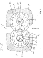
- FIG. 1 shows an example of a Umlaufverdrängermaschine an external gear pump in a cross section.
- a chamber is formed, are rotatably mounted in the two rotors, in the embodiment conveyor wheels 1 and 2, in the form of externally toothed gears about parallel axes of rotation R 1 and R 2 .
- the feed wheel 1 is rotationally driven via a drive member, for example, from the crankshaft of an internal combustion engine of a motor vehicle.
- the conveyor wheels 1 and 2 are meshed with each other in a conveying engagement, in the exemplary embodiment, so that in a rotary drive of the feed wheel 1, the thus meshing conveyor wheel 2 is also rotationally driven.
- the housing 3 forms the conveying wheels 1 and 2 facing in the radial direction in each case a radial sealing surface, which wraps around the respective conveying wheel 1 or 2 over part of its circumference to form a radial sealing gap.
- the housing 3 further forms on each end face of the feed wheel 1 axially facing this an axial sealing surface 3b.
- the pump delivers the fluid on the high pressure side via the outlet 5 and a connected in FIG. 2 schematically shown supply line 13, a cooling device 14 and further via a cleaning device 15 to be supplied to the unit 17 and from there into a sump 18. From the pressure-relieved sump 18, the fluid is sucked in on the low-pressure side via the inlet 4 and thus in a closed fluid circuit circulated by increasing the pressure and subsequent discharge.
- the delivery rate of the pump increases proportionally with the speed of the conveyor wheels 1 and 2. Since an example assumed as a consumer engine from a certain limit speed less lubricating oil absorbs as the pump according to their proportionally with the speed increasing characteristic would promote the delivery rate of the pump from the Limiting speed limited.
- the feed wheel 2 is axially movable to and fro relative to the feed wheel 1, so that the measured parallel to the rotation axes R 1 and R 2 of the engagement length Conveyor wheels 1 and 2 and according to the delivery rate or the delivery volume of the pump can be changed.
- FIG. 2 takes the feed wheel 2 relative to the feed wheel 1 an axial position with a maximum axial overlap, ie maximum engagement length.
- the feed wheel 2 is part of an adjustment with two axially offset to the feed wheel 2 arranged piston 8 and 9, a piston 8 and 9 connecting the bearing section 10 and the rotatably mounted between the piston 8 and 9 on the bearing section 10 conveyor wheel 2.
- the bearing profile 10th connects the pistons 8 and 9 axially rigid and torsionally rigid with each other.
- the pistons 8 and 9 form the conveying wheel 2 directly facing each one of the axial sealing surfaces 8b and 9b for the feed wheel 2.
- the adjustment is axially displaceable in a sliding space of the housing 3 back and forth and mounted against rotation.
- the displacement chamber comprises a fluid space 7 delimited by the adjustment unit on one axial side and a further space likewise delimited by the adjustment unit on the axially opposite side of the adjustment unit, in which a spring member 12 is arranged.
- the fluid chamber 7 can be acted upon by pressure fluid of the high-pressure side of the pump.
- the spring force of the spring member 12 counteracts the pressure force of the pressure fluid.
- the spring member 12 is as exemplified in the DE 102 22 131 B4 described by the introduction of pressure fluid of the high-pressure side relieved when the pump is to promote the fluid with maximum specific flow.
- the pivot bearing of the feed wheel 2 is formed as a sliding bearing between the feed wheel 2 and the bearing profile 10.
- the bearing profile 10 forms an axis about which the conveyor wheel 2 rotates.
- the slide bearing is formed directly between a about the rotation axis R 2 of circular cylindrical circumferential bearing surface 10a of the bearing profile 10 and the bearing surface 10a surrounding bearing mating surface 2a of the feed wheel. 2
- the bearing surface 10a and the bearing counter surface 2a define between them a narrow bearing gap, is conveyed in the funded by the pump fluid of the high pressure side and serves as a lubricant in the bearing gap.
- the clean fluid downstream of the cooling device 14 and the purifier 15 is branched off from the fluid flow conveyed through the chamber and then the supply line 13, i. the fluid pumped by the pump flows through the cooling device 14 and the cleaning device 15 and is returned downstream of these two devices via a return 16 for the purpose of lubricating the rotary bearing to the pump.
- the feedback 16 is connected to a terminal 6 of the housing 3. From the port 6 leads within the housing 3, a lubricant channel into the bearing gap 2a, 10a.
- the lubricant channel comprises the fluid space 7 and then extends directly to the fluid space 7 through the piston 8 and from there into the bearing profile 10.
- the bearing profile 10 accordingly has a hollow cross-section 10b, which forms a portion of the lubricant channel.
- the hollow cross section 10b is connected to the bearing gap via a connecting channel 10c, which is formed as a radial bore.
- the connecting channel 10c leads into the bearing gap at an axially central location, i. it has at least substantially the same distance to the two axial ends of the bearing gap. In this way, the lubricant is distributed evenly and over the shortest path over the entire length of the bearing gap.
- the lubricant flows through discharge channels formed in the sealing surfaces 8b and 9b of the pistons 8 and 9 toward the low-pressure side.
- the flow path of the lubricant is indicated by a dotted line and an arrow pointing into the connecting channel 10c.
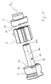
- FIG. 3 shows the components of the adjustment along the axis of rotation R 2 lined up for assembly.
- the fluid space 7 limiting piston 8 and the bearing profile 10 are already firmly connected to each other, preferably only by means of frictional engagement.
- the bearing profile 10 may, for example, be shrunk or otherwise pressed into the pistons 8 and 9.
- the functional distribution of the bearing profile is to be indicated in three axial sections, namely a central bearing portion which forms the bearing surface 10 a, and the two outer end portions, each having a joint portion, preferably frictional engagement, for the form a solid connection with the respective piston 8 or 9.
- the bearing profile 10 is a cylindrical sleeve with a with the exception of the mouth of the connecting channel 10c everywhere smooth, circular cylindrical outer periphery and over almost the entire axial length also smooth, circular cylindrical inner cross section.
- the thickness of the corresponding circular cylindrical shell of this sleeve is smaller than the measured on the axis of rotation R 2 radius of the inner cross section.
- the sleeve is open at one axial end. At the other axial end, it has a bottom through which extends axially a slender channel section, which merges into the further axial channel section 8a, which extends through the piston 8 and opens into the fluid space 7.
- connection between the fluid space 7 and the hollow cross-section 10b has a flow cross-section which is so small that the piston surface facing away from the delivery wheel 2, to which the pressure of the recycled pure oil acts, and thereby the force generated by the pressure is not appreciably reduced ,
- the rapid and uniform distribution of the lubricant in the bearing gap is also a distribution channel 2b, which is formed in the bearing counter surface 2a as a recess which rotates about the axis of rotation R 2 .
- the connecting channel 10c opens into the distribution channel 2b.
- the bearing profile 10 could be formed with a running over the entire length extending hollow cross-section 10b.
- the receiving space for the joint portion of the bearing profile 10 may extend in yet another alternative through the piston 8 continuously, ie by the piston. 8 throughout a cross section have, which corresponds to the cross section in the region of the joining portion of the bearing profile 10.
- the bottom of the bearing profile 10 would form part of the piston surface acted upon by the pressurized fluid in such an alternative embodiment.
- the bearing profile 10 of the embodiment could also be reversed, so that its bottom would be arranged in the receiving space of the piston 8.
- the channel section in the bottom of the bearing profile 10 could be dispensed with in such an embodiment. If the bottom is closed, that is, has no channel section, the piston 9 could also have an axially continuously extending receiving space for the bearing profile 10.
- the bearing profile 10 extends through the feed wheel 2 and projects with its two axial ends of the bearing profile 10 forming joining sections in one of the pistons 8 and 9.
- the pistons 8 and 9 each have a bag receptacle in which the associated joining portion of the bearing section 10 projects and held over its outer periphery with pressing force.
- the bag receptacles of the pistons 8 and 9 are each formed as a circular blind hole.
- the piston 9 closes the hollow cross-section 10b or the lubricant channel at the relevant end face of the bearing profile 10, while the channel 8a leads through the piston 8.
- the feed wheel 1 is torsionally rigid and axially immovably connected to a bearing profile 11 which forms the drive shaft of the pump.
- the bearing profile 11 is rotatably mounted about the rotation axis R 1 .
- the pivot bearing for the feed wheel 1 comprises axially to the feed wheel 1 offset left and right of the feed wheel 1 arranged bearing structures, one of which forms the housing 3 and the other one firmly inserted in the housing 3 and therefore also designated 3 insert.
- the bearing profile 11 extends through these two left and right of the impeller 1 arranged bearing structures 3.
- the bearing profile 11 forms with each of these two bearing structures 3 a sliding bearing.
- the bearing profile 11 has at its outer periphery per slide bearing a bearing surface 11 a.
- the bearing structures 3 each form a bearing counter surface 3 a, which surrounds the respective associated bearing surface 11 a circumferentially to form a narrow bearing gap.
- the two bearing gaps formed between the bearing profile 11 and the bearing structures 3 are supplied to lubricate the rotary bearing in a first embodiment with raw fluid of the high pressure side as a lubricant. In a further development, these two bearing gaps are also lubricated with the clean fluid.
- the Bearing 11 of the embodiment is formed as a full wave, but may also be a hollow shaft with a hollow cross section, which extends over at least a major part of the axial length of the bearing profile 11 in a development instead.
- the raw fluid or alternatively the pure fluid can be guided through the hollow shaft from the inside into the two bearing gaps.
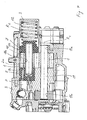
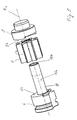
- FIGS. 4 and 5 show a circulation displacement machine in a second embodiment and also as an external gear pump.
- the rotary bearing of the impeller 2 is lubricated in a conventional manner with the raw fluid of the high pressure side of the chamber. Accordingly, the lubricant channel leads within the chamber in the bearing gap.
- the lubricating raw fluid is supplied into the bearing gap from the high pressure side of the chamber in a feed channel formed in one of the two axial sealing surfaces 8b and 9b and flows through a discharge channel in the axial sealing surface of the axially opposite piston 8 or 9 to the low pressure side the chamber again. Accordingly, the lubricant channel no longer leads through the piston 8 in the bearing section 10.
- the piston 8 has a closed piston crown or the bearing profile 10 a closed bottom, which also includes the case that both the bottom of the piston 8 and the bottom of the Bearing profiles 10 may be closed.
- the fluid space 7 is applied to the high pressure side raw fluid as in conventional pumps, with the raw fluid being branched directly from the chamber at the outlet 5 or downstream of the chamber.
- the fluid space 7 may also be charged with the clean fluid as in the first embodiment, to use a control pressure for the adjustment of the adjustment, which corresponds to the fluid pressure in the immediate vicinity of the unit 17 to be supplied more accurate than the pressure on the high pressure side of the chamber.
- the pump corresponds to that of the first embodiment.
Landscapes
- Engineering & Computer Science (AREA)
- Mechanical Engineering (AREA)
- General Engineering & Computer Science (AREA)
- Rotary Pumps (AREA)
- Support Of The Bearing (AREA)
- Reciprocating Pumps (AREA)
- Sliding-Contact Bearings (AREA)
Applications Claiming Priority (1)
| Application Number | Priority Date | Filing Date | Title |
|---|---|---|---|
| DE102009019419.3A DE102009019419B4 (de) | 2009-04-29 | 2009-04-29 | Umlaufverdrängermaschine mit vereinfachter Lagerachse oder -welle |
Publications (2)
| Publication Number | Publication Date |
|---|---|
| EP2249038A2 true EP2249038A2 (fr) | 2010-11-10 |
| EP2249038A3 EP2249038A3 (fr) | 2012-11-28 |
Family
ID=42650496
Family Applications (1)
| Application Number | Title | Priority Date | Filing Date |
|---|---|---|---|
| EP10161300A Withdrawn EP2249038A3 (fr) | 2009-04-29 | 2010-04-28 | Machine à engrenage externe dotée d'un palier pour l'axe simplifié |
Country Status (2)
| Country | Link |
|---|---|
| EP (1) | EP2249038A3 (fr) |
| DE (1) | DE102009019419B4 (fr) |
Families Citing this family (1)
| Publication number | Priority date | Publication date | Assignee | Title |
|---|---|---|---|---|
| DE102012209622A1 (de) * | 2012-06-08 | 2013-12-12 | Robert Bosch Gmbh | Zahnradmaschine mit hydrodynamisch und hydrostatisch gelagertem Lagerzapfen |
Citations (1)
| Publication number | Priority date | Publication date | Assignee | Title |
|---|---|---|---|---|
| DE10222131B4 (de) | 2002-05-17 | 2005-05-12 | SCHWäBISCHE HüTTENWERKE GMBH | Verdrängerpumpe mit Fördervolumenverstellung |
Family Cites Families (9)
| Publication number | Priority date | Publication date | Assignee | Title |
|---|---|---|---|---|
| US2571377A (en) * | 1947-05-15 | 1951-10-16 | Prec Developments Co Ltd | Rotary displacement pump |
| US2988009A (en) * | 1956-07-23 | 1961-06-13 | Jr Frederick Kraissl | External gear pump |
| FR2033502A5 (fr) * | 1969-02-26 | 1970-12-04 | Hydroperfect Internal | |
| DE3642660A1 (de) * | 1986-01-15 | 1987-07-16 | Barmag Barmer Maschf | Zahnradpumpe |
| US20080240968A1 (en) * | 2004-02-13 | 2008-10-02 | Chiu Hing L | Low Cost Gear Fuel Pump |
| DE102004052558A1 (de) * | 2004-10-29 | 2006-05-04 | Saurer Gmbh & Co. Kg | Zahnradpumpe |
| DE202007004103U1 (de) * | 2007-03-16 | 2007-06-06 | Lincoln Gmbh | Schmierritzel und Schmiereinrichtung |
| DE102007051779A1 (de) * | 2007-07-11 | 2009-01-15 | Audi Ag | Zahnradschmiermittelpumpe, insbesondere Außenzahnradpumpe |
| DE102007039589A1 (de) * | 2007-08-22 | 2009-02-26 | Voigt, Dieter, Dipl.-Ing. | Regelölpumpe mit verstellwegabhängiger Öldruckregelung |
-
2009
- 2009-04-29 DE DE102009019419.3A patent/DE102009019419B4/de not_active Expired - Fee Related
-
2010
- 2010-04-28 EP EP10161300A patent/EP2249038A3/fr not_active Withdrawn
Patent Citations (1)
| Publication number | Priority date | Publication date | Assignee | Title |
|---|---|---|---|---|
| DE10222131B4 (de) | 2002-05-17 | 2005-05-12 | SCHWäBISCHE HüTTENWERKE GMBH | Verdrängerpumpe mit Fördervolumenverstellung |
Also Published As
| Publication number | Publication date |
|---|---|
| EP2249038A3 (fr) | 2012-11-28 |
| DE102009019419B4 (de) | 2016-01-14 |
| DE102009019419A1 (de) | 2010-11-04 |
Similar Documents
| Publication | Publication Date | Title |
|---|---|---|
| DE112015004113T5 (de) | Kompressor mit Ölrückführeinheit | |
| AT505439B1 (de) | Exzenterpumpe | |
| EP2916007B1 (fr) | Pompe à vis | |
| EP3236074B1 (fr) | Pompe rotative comprenant une rainure de graissage dans une nervure d'étanchéité | |
| DE2437624C2 (fr) | ||
| DE102011101648B4 (de) | Schraubenmaschine, insbesondere Schraubenspindelpumpe | |
| WO2000039465A1 (fr) | Ensemble de pompes comportant deux pompes hydrauliques | |
| EP2961985B1 (fr) | Installation de compression d'un réfrigérant | |
| EP2672119B1 (fr) | Machine à roue dentée dotée d'un tourillon logé de façon hydrodynamique et hydrostatique | |
| EP1664540B1 (fr) | Machine a piston rotatif | |
| DE102009019418B4 (de) | Umlaufverdrängerpumpe mit verbesserter Lagerschmierung | |
| WO2005024237A1 (fr) | Machine a piston rotatif | |
| EP0846861B1 (fr) | Pompe annulaire à engrenages continuellement variable | |
| DE102009019419B4 (de) | Umlaufverdrängermaschine mit vereinfachter Lagerachse oder -welle | |
| DE102005052346A1 (de) | Ölpumpe | |
| WO2016198365A1 (fr) | Dispositif de transmission d'un couple d'un dispositif d'entraînement vers le rouleau d'une cage de laminoir | |
| DE4135904A1 (de) | Kolbenpumpe, insbesondere radialkolbenpumpe | |
| DE3225790A1 (de) | Pumpe oder motor | |
| DE19962798C2 (de) | Spiralverdichter oder Spiralpumpe | |
| DE202004004231U1 (de) | Volumenstromveränderbare Verdrängerpumpe | |
| DE102014207070B4 (de) | Pumpe | |
| DE3603773A1 (de) | Zahnradmaschine | |
| DE3042836C2 (de) | Hochdruck-Kolbenpumpe für Flüssigkeiten, vorzugsweise für Wasser | |
| DE2061567A1 (de) | Rotationskompressor | |
| DE102023128576A1 (de) | Kreiselradumpe mit ausfahrbaren Schaufeln |
Legal Events
| Date | Code | Title | Description |
|---|---|---|---|
| PUAI | Public reference made under article 153(3) epc to a published international application that has entered the european phase |
Free format text: ORIGINAL CODE: 0009012 |
|
| AK | Designated contracting states |
Kind code of ref document: A2 Designated state(s): AT BE BG CH CY CZ DE DK EE ES FI FR GB GR HR HU IE IS IT LI LT LU LV MC MK MT NL NO PL PT RO SE SI SK SM TR |
|
| AX | Request for extension of the european patent |
Extension state: AL BA ME RS |
|
| PUAL | Search report despatched |
Free format text: ORIGINAL CODE: 0009013 |
|
| AK | Designated contracting states |
Kind code of ref document: A3 Designated state(s): AT BE BG CH CY CZ DE DK EE ES FI FR GB GR HR HU IE IS IT LI LT LU LV MC MK MT NL NO PL PT RO SE SI SK SM TR |
|
| AX | Request for extension of the european patent |
Extension state: AL BA ME RS |
|
| RIC1 | Information provided on ipc code assigned before grant |
Ipc: F04C 15/00 20060101ALI20121023BHEP Ipc: F01C 21/02 20060101ALI20121023BHEP Ipc: F04C 2/18 20060101AFI20121023BHEP |
|
| 17P | Request for examination filed |
Effective date: 20130528 |
|
| RBV | Designated contracting states (corrected) |
Designated state(s): AT BE BG CH CY CZ DE DK EE ES FI FR GB GR HR HU IE IS IT LI LT LU LV MC MK MT NL NO PL PT RO SE SI SK SM TR |
|
| 17Q | First examination report despatched |
Effective date: 20130801 |
|
| STAA | Information on the status of an ep patent application or granted ep patent |
Free format text: STATUS: THE APPLICATION IS DEEMED TO BE WITHDRAWN |
|
| 18D | Application deemed to be withdrawn |
Effective date: 20161101 |