EP2249042B1 - Pompe submersible - Google Patents
Pompe submersible Download PDFInfo
- Publication number
- EP2249042B1 EP2249042B1 EP20090006299 EP09006299A EP2249042B1 EP 2249042 B1 EP2249042 B1 EP 2249042B1 EP 20090006299 EP20090006299 EP 20090006299 EP 09006299 A EP09006299 A EP 09006299A EP 2249042 B1 EP2249042 B1 EP 2249042B1
- Authority
- EP
- European Patent Office
- Prior art keywords
- immersion pump
- sealing gas
- support
- protective casing
- support tube
- Prior art date
- Legal status (The legal status is an assumption and is not a legal conclusion. Google has not performed a legal analysis and makes no representation as to the accuracy of the status listed.)
- Active
Links
Images
Classifications
-
- F—MECHANICAL ENGINEERING; LIGHTING; HEATING; WEAPONS; BLASTING
- F04—POSITIVE - DISPLACEMENT MACHINES FOR LIQUIDS; PUMPS FOR LIQUIDS OR ELASTIC FLUIDS
- F04D—NON-POSITIVE-DISPLACEMENT PUMPS
- F04D13/00—Pumping installations or systems
- F04D13/02—Units comprising pumps and their driving means
- F04D13/06—Units comprising pumps and their driving means the pump being electrically driven
- F04D13/08—Units comprising pumps and their driving means the pump being electrically driven for submerged use
-
- F—MECHANICAL ENGINEERING; LIGHTING; HEATING; WEAPONS; BLASTING
- F04—POSITIVE - DISPLACEMENT MACHINES FOR LIQUIDS; PUMPS FOR LIQUIDS OR ELASTIC FLUIDS
- F04D—NON-POSITIVE-DISPLACEMENT PUMPS
- F04D15/00—Control, e.g. regulation, of pumps, pumping installations or systems
- F04D15/0077—Safety measures
-
- F—MECHANICAL ENGINEERING; LIGHTING; HEATING; WEAPONS; BLASTING
- F04—POSITIVE - DISPLACEMENT MACHINES FOR LIQUIDS; PUMPS FOR LIQUIDS OR ELASTIC FLUIDS
- F04D—NON-POSITIVE-DISPLACEMENT PUMPS
- F04D29/00—Details, component parts, or accessories
- F04D29/08—Sealings
- F04D29/10—Shaft sealings
- F04D29/106—Shaft sealings especially adapted for liquid pumps
- F04D29/108—Shaft sealings especially adapted for liquid pumps the sealing fluid being other than the working liquid or being the working liquid treated
Definitions
- the invention relates to a submersible pump, with a support tube and at least one vertically aligned shaft, in particular a plurality of vertically aligned shafts connected in series, which are each provided with bearing and sealing units in the support tube, wherein the pump hydraulics of the submersible pump is arranged in the medium to be pumped and in the submersible pump abandoned, in particular gaseous medium flows below the lowest bearing and sealing unit in the media area of the submersible pump.
- the object of the invention is to avoid the aforementioned disadvantages and to improve a submersible pump in such a way that safe use is also possible in environments with an inflammatory atmosphere.
- the support tube is at least partially surrounded by at least one peripheral, a portion of the support tube thermally and materially from the medium, insulating protective jacket.
- At least one protective jacket is provided at least in the region of a bearing and sealing unit, so that a direct isolation of the particularly high-risk storage area is given.
- a protective jacket extending over the entire length of the carrying tube can be provided, so that an isolation of all hazardous areas in the carrying tube, ie. H. also all arranged in the support tube bearing and sealing units, given a technically simple design.
- a less noble material can be used for the support tube due to its then complete encapsulation.
- At least one protective jacket provided with a particular provided in the upper region of the protective sheath Sperrgaszu111 impart and be traversed by sealing gas, in particular a plurality of such trapped by sealing gas protective sheaths may be connected in series, so that an inerting of the protective sheath is given.
- At least one protective jacket provided with a barrier gas supply line can also be provided with a barrier gas discharge line provided in particular in the lower region of the protective jacket, in particular several such protective jackets connected in series, so that targeted removal of the barrier gas is possible and measured values of the specified barrier gas can be detected for evaluation are.
- At least one bearing and sealing unit surrounded by a protective casing can be provided with a fuse which fails at a temperature level which exceeds the normal operating temperatures and occurs, for example, during bearing damage or sealing damage, and thus a targeted gas outlet from the bearing and sealing unit ,
- a gas passage from the storage and sealing unit in the protective jacket, in the medium or in a line to the environment allows so by increased gas flow on the one hand, increased heat dissipation results and on the other hand, the increased gas flow also for detecting a lying above the normal operating temperatures Temperature is detected.
- At least one seal of a bearing and sealing unit can be designed such that increased radial leakage is increased sealing gas leakage, in particular seal a bearing and sealing unit at least a lip seal or the like include, so that on the one hand, an increased heat dissipation results and on the other increased gas flow rate can also be detected for the detection of a radial shaft displacement.
- At least one detection device and in particular also an evaluation device can be provided for the purge gas volume flow flowing through the purge gas supply line for at least one protective jacket so that an evaluation of a wide variety of data, in particular of temperature and volumetric flow, is possible and thus conclusions about the state and the operating state of the submersible pump are possible.
- At least one detection device and in particular also an evaluation device can be provided for the barrier gas volume flow flowing through the barrier gas discharge line for at least one protective jacket, so that an evaluation of various data, in particular of temperature and volume flow, is possible and thus conclusions about the state and operating state of the submersible pump possible are.
- the support tube itself may be provided with a particular provided in the upper region of the support tube Sperrgaszu211 Koch and traversed by sealing gas, so that an inertization of the support tube is already given.
- a detection device and in particular also an evaluation device for the flowing through the Sperrgaszumol exploit the support tube sealing gas volume flow can be provided so that an evaluation of various data, in particular temperature and flow rate, is possible and thus conclusions about the state and operating condition of the submersible pump are possible.
- sealing gas in particular provided with a Sperrgasab2020 Koch, gas barrier may be provided to keep the flammable atmosphere of the storage and sealing unit away.
- a detection device and in particular also an evaluation device can be provided for the barrier gas volume flow respectively flowing through the barrier gas supply line and / or through the blocking gas discharge line for the support tube or the gas barrier, so that an evaluation of various data, in particular of temperature and volume flow, is possible and thus Conclusions on the condition and operating condition of the submersible pump are possible.
- a common evaluation device for the data of at least two different detection devices can be designed for a simplified technical design including a component reduction.
- an emergency bearing for catching the shaft at an increased axial and / or radial shaft displacement Failure of the bearing and sealing unit may be provided so that uncontrolled displacements of the shaft can be avoided.
- a cooling device in particular in the form of liquid cooling, can be provided, so that active cooling can take place, which also allows use in hot and very hot media whose temperature may even exceed the permissible level Operating temperature of the insulated by the protective jacket components.
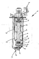
- FIGURE shows a submersible pump 1, which comprises a support tube 2 and a vertically aligned shaft 3.
- the shaft 3 is provided with bearing and sealing units 4 in the support tube 2, and the pump hydraulics 5 of the submersible pump 1 is arranged in the medium to be pumped and not shown in the drawing, wherein the discontinued in the submersible pump 1, in particular gaseous medium below the lowest storage and sealing unit 4 flows into the media area of the submersible pump 1.
- the support tube 2 is partially surrounded in the areas of the storage and sealing units 4 each with a circumferential, the corresponding portion of the support tube 2 thermally and materially insulating from the environment protective jacket 6, which includes not only the actual lateral surface 7 but also upper and lower end elements 8 , Thus, there is a direct isolation of the particularly high-risk storage area.
- the protective jacket 6 is on the upper side gas-tight and the underside almost completely gas-tight with a narrow opening 9 at its lowest point formed.
- the protective jacket 6 is provided in each case for an inerting of the protective jacket 6 with a provided in the upper region of the protective jacket 6 Sperrgaszu111 Koch 10 and is thereby flowed through by sealing gas, wherein an outlet of the sealing gas is only possible on the underside through the opening 9.
- a barrier gas supply line 10 leads to the upper region of the lower protective jacket 6.
- a combined detection and evaluation device 11 is provided for flowing through the Sperrgaszumoltechnischesus, so that an evaluation of various data, in particular temperature and flow rate, is possible and thus conclusions on the state and operating condition of the submersible pump 1 possible are.
- the support tube 2 is also provided in its central region with a Sperrgaszutechnologietechnisch 10 and to be traversed by sealing gas, so that an inerting of the support tube 2 is given, with an exit of the sealing gas via the opening 9.
- sealing gas can come from the carrier tube 2.
- the protective jacket 6 is provided in each case for one provided with a provided in the lower region of the respective protective sheath 6 Sperrgasabtechnologietechnisch 12, the Sperrgasabdiestechnisch 12 of the upper protective sheath 6, the SperrgaszuSciencetechnisch 10 of the lower protective sheath 6 forms.
Landscapes
- Engineering & Computer Science (AREA)
- Mechanical Engineering (AREA)
- General Engineering & Computer Science (AREA)
- Structures Of Non-Positive Displacement Pumps (AREA)
Claims (16)
- Pompe immergée (1), avec un tube porteur (2) et avec au moins un arbre (3) orienté verticalement en utilisation, les arbres étant chacun prévus avec des unités de palier et d'étanchéité (4) dans le tube porteur (2), sachant que le système hydraulique de pompe (5) de la pompe immergée (1) est disposé dans le fluide à pomper et que le fluide alimenté dans la pompe immergée (1) s'écoule en dessous de l'unité de palier et d'étanchéité la plus basse dans la zone de fluide de la pompe immergée (1), caractérisée en ce que le tube porteur (2) est entouré au moins partiellement par au moins une enveloppe de protection périphérique (6), isolant thermiquement et matériellement par rapport au fluide une région partielle du tube porteur (2), sachant qu'au moins une enveloppe de protection (6) est prévue au moins dans la région d'une unité de palier et d'étanchéité (4).
- Pompe immergée (1) selon la revendication précédente, caractérisée en ce qu'il est prévu une enveloppe de protection (6) s'étendant sur toute la longueur du tube porteur (2).
- Pompe immergée (1) selon l'une des revendications précédentes, caractérisée en ce qu'au moins une enveloppe de protection (6) est réalisée et installée en étanchéité aux gaz au moins sur le dessus, avec une étroite ouverture (9) en son point le plus bas.
- Pompe immergée (1) selon l'une des revendications précédentes, caractérisée en ce qu'au moins une unité de palier et d'étanchéité entourée par une enveloppe de protection (6) est pourvue d'un fusible qui, dans le cas d'un niveau de température qui se situe au-dessus des températures normales de fonctionnement et qui survient par exemple dans le cas d'un endommagement d'un palier ou d'un endommagement d'un joint d'étanchéité, claque et permet ainsi un échappement intentionnel de gaz hors de l'unité de palier et d'étanchéité, dans le fluide ou dans une conduite menant vers l'environnement.
- Pompe immergée (1) selon l'une des revendications précédentes, caractérisée en ce qu'au moins un joint d'étanchéité d'une unité de palier et d'étanchéité (4) est réalisé de telle sorte qu'une fuite accrue de gaz d'arrêt est obtenue dans le cas d'un décalage radial de l'arbre.
- Pompe immergée (1) selon l'une des revendications précédentes, caractérisée en ce qu'au moins une enveloppe de protection (6) est pourvue d'une conduite (10) d'alimentation en gaz d'arrêt et est traversée par un flux de gaz d'arrêt.
- Pompe immergée (1) selon la revendication précédente, caractérisée en ce qu'au moins une enveloppe de protection (6) pourvue d'une conduite (10) d'alimentation en gaz d'arrêt est pourvue d'une conduite (12) d'évacuation de gaz d'arrêt.
- Pompe immergée (1) selon la revendication 6 ou 7, caractérisée en ce qu'il est prévu au moins un dispositif de détection (1) ainsi qu'un dispositif d'analyse (11) pour le débit volumique de gaz d'arrêt s'écoulant par la conduite (10) d'alimentation en gaz d'arrêt pour au moins une enveloppe de protection (6).
- Pompe immergée (1) selon la revendication 7 ou selon la revendication 8 en combinaison avec la revendication 7, caractérisée en ce qu'il est prévu au moins un dispositif de détection (11) ainsi qu'un dispositif d'analyse (11) pour le débit volumique de gaz d'arrêt s'écoulant par la conduite (12) d'évacuation de gaz d'arrêt pour au moins une enveloppe de protection (6).
- Pompe immergée (1) selon l'une des revendications précédentes, caractérisée en ce que le tube porteur (2) est pourvu d'une conduite (10) d'alimentation en gaz d'arrêt et est traversé par un flux de gaz d'arrêt.
- Pompe immergée (1) selon la revendication précédente, caractérisée en ce qu'il est prévu un dispositif de détection (11) ainsi qu'un dispositif d'analyse (11) pour le débit volumique de gaz d'arrêt s'écoulant par la conduite (10) d'alimentation en gaz d'arrêt du tube porteur (2).
- Pompe immergée (1) selon l'une des revendications précédentes, caractérisée en ce qu'une barrière de gaz supplémentaire (13), fonctionnant sans contact et sans frottement et traversée par un flux de gaz d'arrêt, est prévue en dessous de l'unité de palier et d'étanchéité (4) la plus basse.
- Pompe immergée (1) selon la revendication précédente, caractérisée en ce que la barrière de gaz (13) est pourvue d'une conduite (12) d'évacuation de gaz d'arrêt, et il est prévu un dispositif de détection (11) pour le débit volumique de gaz d'arrêt s'écoulant respectivement par la conduite (12) d'évacuation de gaz d'arrêt pour le tube porteur (2) et pour la barrière de gaz (13).
- Pompe immergée (1) selon l'une des revendications 8, 9, 11 ou 13, caractérisée en ce qu'un dispositif d'analyse (11) commun est réalisé pour les données d'au moins deux dispositifs de détection (11) différents.
- Pompe immergée (1) selon l'une des revendications précédentes, caractérisée en ce qu'il est prévu, dans la région d'au moins une unité de palier et d'étanchéité (4), un palier de secours pour intercepter l'arbre (3) dans le cas d'un décalage axial et/ou radial accru de l'arbre suite à la défaillance de l'unité de palier et d'étanchéité (4).
- Pompe immergée (1) selon l'une des revendications précédentes, caractérisée en ce qu'un dispositif de refroidissement est prévu à l'intérieur d'au moins une région entourée par une enveloppe de protection (6).
Priority Applications (1)
| Application Number | Priority Date | Filing Date | Title |
|---|---|---|---|
| EP20090006299 EP2249042B1 (fr) | 2009-05-08 | 2009-05-08 | Pompe submersible |
Applications Claiming Priority (1)
| Application Number | Priority Date | Filing Date | Title |
|---|---|---|---|
| EP20090006299 EP2249042B1 (fr) | 2009-05-08 | 2009-05-08 | Pompe submersible |
Publications (2)
| Publication Number | Publication Date |
|---|---|
| EP2249042A1 EP2249042A1 (fr) | 2010-11-10 |
| EP2249042B1 true EP2249042B1 (fr) | 2013-02-27 |
Family
ID=41051130
Family Applications (1)
| Application Number | Title | Priority Date | Filing Date |
|---|---|---|---|
| EP20090006299 Active EP2249042B1 (fr) | 2009-05-08 | 2009-05-08 | Pompe submersible |
Country Status (1)
| Country | Link |
|---|---|
| EP (1) | EP2249042B1 (fr) |
Families Citing this family (2)
| Publication number | Priority date | Publication date | Assignee | Title |
|---|---|---|---|---|
| DK3045729T3 (da) | 2015-01-13 | 2019-11-04 | Sulzer Management Ag | Lejearrangement til en dykpumpe |
| US20220299033A1 (en) * | 2021-03-18 | 2022-09-22 | Gscd Corp. | Gas Seal Column Pump for Elevated Temperature Applications |
Family Cites Families (5)
| Publication number | Priority date | Publication date | Assignee | Title |
|---|---|---|---|---|
| GB234546A (en) * | 1924-02-26 | 1925-05-26 | Arthur Crawley Potter | Improvements in or relating to deep well pumping installations and the like |
| US2764943A (en) * | 1951-10-13 | 1956-10-02 | Surface Combustion Corp | Pump system |
| CH450925A (de) * | 1965-07-30 | 1968-05-15 | Flux Geraete Gmbh | Pumpe, insbesondere Fasspumpe |
| DE2257718A1 (de) * | 1972-11-24 | 1974-05-30 | Gerhard Lutz | Geraet zum bewegen von fluessigkeiten, insbesondere fasspumpe |
| FR2717535A1 (fr) * | 1994-03-17 | 1995-09-22 | Siebec Sa | Pompe verticale. |
-
2009
- 2009-05-08 EP EP20090006299 patent/EP2249042B1/fr active Active
Also Published As
| Publication number | Publication date |
|---|---|
| EP2249042A1 (fr) | 2010-11-10 |
Similar Documents
| Publication | Publication Date | Title |
|---|---|---|
| EP2406527B1 (fr) | Joint d'arbre pour une turbomachine | |
| DE112010005712B4 (de) | Fluidsteuerventil | |
| DE2408660C3 (de) | Doppelt wirkende Gleitringdichtung | |
| EP3163086B1 (fr) | Unité d'entraînement de pompes destinée à transporter un fluide de processus | |
| DE1182000B (de) | Gleitringdichtung | |
| DE102008018407A1 (de) | Unterwasserförderaggregat | |
| DE102015100546A1 (de) | Heißgasventil, insbesondere AGR-Ventil | |
| EP2249042B1 (fr) | Pompe submersible | |
| EP2286118A1 (fr) | Agencement d'étanchéité à anneau glissant avec dispositif intégré de transfert thermique | |
| EP3140572A1 (fr) | Ensemble de garniture d'étanchéité à bagues de glissement ayant une séparation de gaz améliorée | |
| DE2034586A1 (de) | Einrichtung zum Abdichten und Kuhlen der Antriebswelle von Kreiselpumpen zur Forderung heißer Medien | |
| DE102018113636A1 (de) | Magnetgekuppelte Pumpe mit doppelschaligem Spalttopf | |
| CH334061A (de) | Motorpumpenaggregat | |
| DE2901474A1 (de) | Selbstkuehlende mechanische dichtung | |
| DE102015110988A1 (de) | Leckreduzierte Drehdurchführung | |
| EP2802194B1 (fr) | Boîtier encapsulé résistant à la pression doté d'un dispositif de refroidissement | |
| EP0690204B1 (fr) | Turbine à vapeur ayant au moins deux joint pour assurer l'étanchéité du carter | |
| DE3404964C2 (de) | Keiselpumpe mit einer Wellenabdichtung | |
| EP3884165A1 (fr) | Dispositif de pompage | |
| DE102014203464A1 (de) | Anlage mit einer Gasdichtung, Verfahren zum Betrieb | |
| EP0744551B1 (fr) | Pompe centrifuge pour le transport de fluides chauds | |
| EP2171238A1 (fr) | Turbomachine ou machine à déplacement comprenant des paliers magnétiques | |
| DE69010311T2 (de) | Einrichtung zum Auslass in die Atmosphäre eines von einem Flugzeugüberdruckventil freigelassenen warmen Flüssigkeitsstroms. | |
| EP1674732B1 (fr) | Dispositif de prévention contre une explosion pour appareil non électrique | |
| DE2743132C2 (de) | Einrichtung zur Überwachung des Strömungszustandes eines durch ein Rohr strömenden flüssigen Mediums |
Legal Events
| Date | Code | Title | Description |
|---|---|---|---|
| PUAI | Public reference made under article 153(3) epc to a published international application that has entered the european phase |
Free format text: ORIGINAL CODE: 0009012 |
|
| AK | Designated contracting states |
Kind code of ref document: A1 Designated state(s): AT BE BG CH CY CZ DE DK EE ES FI FR GB GR HR HU IE IS IT LI LT LU LV MC MK MT NL NO PL PT RO SE SI SK TR |
|
| AX | Request for extension of the european patent |
Extension state: AL BA RS |
|
| 17P | Request for examination filed |
Effective date: 20110413 |
|
| 17Q | First examination report despatched |
Effective date: 20110530 |
|
| RIC1 | Information provided on ipc code assigned before grant |
Ipc: F04D 15/00 20060101ALI20111206BHEP Ipc: F04D 13/08 20060101AFI20111206BHEP |
|
| GRAP | Despatch of communication of intention to grant a patent |
Free format text: ORIGINAL CODE: EPIDOSNIGR1 |
|
| GRAS | Grant fee paid |
Free format text: ORIGINAL CODE: EPIDOSNIGR3 |
|
| GRAA | (expected) grant |
Free format text: ORIGINAL CODE: 0009210 |
|
| AK | Designated contracting states |
Kind code of ref document: B1 Designated state(s): AT BE BG CH CY CZ DE DK EE ES FI FR GB GR HR HU IE IS IT LI LT LU LV MC MK MT NL NO PL PT RO SE SI SK TR |
|
| REG | Reference to a national code |
Ref country code: GB Ref legal event code: FG4D Free format text: NOT ENGLISH |
|
| REG | Reference to a national code |
Ref country code: CH Ref legal event code: EP |
|
| REG | Reference to a national code |
Ref country code: AT Ref legal event code: REF Ref document number: 598670 Country of ref document: AT Kind code of ref document: T Effective date: 20130315 |
|
| REG | Reference to a national code |
Ref country code: IE Ref legal event code: FG4D Free format text: LANGUAGE OF EP DOCUMENT: GERMAN |
|
| REG | Reference to a national code |
Ref country code: DE Ref legal event code: R096 Ref document number: 502009006326 Country of ref document: DE Effective date: 20130425 |
|
| REG | Reference to a national code |
Ref country code: LT Ref legal event code: MG4D |
|
| PG25 | Lapsed in a contracting state [announced via postgrant information from national office to epo] |
Ref country code: IS Free format text: LAPSE BECAUSE OF FAILURE TO SUBMIT A TRANSLATION OF THE DESCRIPTION OR TO PAY THE FEE WITHIN THE PRESCRIBED TIME-LIMIT Effective date: 20130627 Ref country code: BG Free format text: LAPSE BECAUSE OF FAILURE TO SUBMIT A TRANSLATION OF THE DESCRIPTION OR TO PAY THE FEE WITHIN THE PRESCRIBED TIME-LIMIT Effective date: 20130527 Ref country code: NO Free format text: LAPSE BECAUSE OF FAILURE TO SUBMIT A TRANSLATION OF THE DESCRIPTION OR TO PAY THE FEE WITHIN THE PRESCRIBED TIME-LIMIT Effective date: 20130527 Ref country code: SE Free format text: LAPSE BECAUSE OF FAILURE TO SUBMIT A TRANSLATION OF THE DESCRIPTION OR TO PAY THE FEE WITHIN THE PRESCRIBED TIME-LIMIT Effective date: 20130227 Ref country code: ES Free format text: LAPSE BECAUSE OF FAILURE TO SUBMIT A TRANSLATION OF THE DESCRIPTION OR TO PAY THE FEE WITHIN THE PRESCRIBED TIME-LIMIT Effective date: 20130607 Ref country code: LT Free format text: LAPSE BECAUSE OF FAILURE TO SUBMIT A TRANSLATION OF THE DESCRIPTION OR TO PAY THE FEE WITHIN THE PRESCRIBED TIME-LIMIT Effective date: 20130227 |
|
| REG | Reference to a national code |
Ref country code: NL Ref legal event code: VDEP Effective date: 20130227 |
|
| PG25 | Lapsed in a contracting state [announced via postgrant information from national office to epo] |
Ref country code: SI Free format text: LAPSE BECAUSE OF FAILURE TO SUBMIT A TRANSLATION OF THE DESCRIPTION OR TO PAY THE FEE WITHIN THE PRESCRIBED TIME-LIMIT Effective date: 20130227 Ref country code: PL Free format text: LAPSE BECAUSE OF FAILURE TO SUBMIT A TRANSLATION OF THE DESCRIPTION OR TO PAY THE FEE WITHIN THE PRESCRIBED TIME-LIMIT Effective date: 20130227 Ref country code: FI Free format text: LAPSE BECAUSE OF FAILURE TO SUBMIT A TRANSLATION OF THE DESCRIPTION OR TO PAY THE FEE WITHIN THE PRESCRIBED TIME-LIMIT Effective date: 20130227 Ref country code: PT Free format text: LAPSE BECAUSE OF FAILURE TO SUBMIT A TRANSLATION OF THE DESCRIPTION OR TO PAY THE FEE WITHIN THE PRESCRIBED TIME-LIMIT Effective date: 20130627 Ref country code: GR Free format text: LAPSE BECAUSE OF FAILURE TO SUBMIT A TRANSLATION OF THE DESCRIPTION OR TO PAY THE FEE WITHIN THE PRESCRIBED TIME-LIMIT Effective date: 20130528 Ref country code: LV Free format text: LAPSE BECAUSE OF FAILURE TO SUBMIT A TRANSLATION OF THE DESCRIPTION OR TO PAY THE FEE WITHIN THE PRESCRIBED TIME-LIMIT Effective date: 20130227 |
|
| PGFP | Annual fee paid to national office [announced via postgrant information from national office to epo] |
Ref country code: NL Payment date: 20130523 Year of fee payment: 5 |
|
| PG25 | Lapsed in a contracting state [announced via postgrant information from national office to epo] |
Ref country code: HR Free format text: LAPSE BECAUSE OF FAILURE TO SUBMIT A TRANSLATION OF THE DESCRIPTION OR TO PAY THE FEE WITHIN THE PRESCRIBED TIME-LIMIT Effective date: 20130227 |
|
| PG25 | Lapsed in a contracting state [announced via postgrant information from national office to epo] |
Ref country code: SK Free format text: LAPSE BECAUSE OF FAILURE TO SUBMIT A TRANSLATION OF THE DESCRIPTION OR TO PAY THE FEE WITHIN THE PRESCRIBED TIME-LIMIT Effective date: 20130227 Ref country code: CZ Free format text: LAPSE BECAUSE OF FAILURE TO SUBMIT A TRANSLATION OF THE DESCRIPTION OR TO PAY THE FEE WITHIN THE PRESCRIBED TIME-LIMIT Effective date: 20130227 Ref country code: NL Free format text: LAPSE BECAUSE OF FAILURE TO SUBMIT A TRANSLATION OF THE DESCRIPTION OR TO PAY THE FEE WITHIN THE PRESCRIBED TIME-LIMIT Effective date: 20130227 Ref country code: RO Free format text: LAPSE BECAUSE OF FAILURE TO SUBMIT A TRANSLATION OF THE DESCRIPTION OR TO PAY THE FEE WITHIN THE PRESCRIBED TIME-LIMIT Effective date: 20130227 Ref country code: EE Free format text: LAPSE BECAUSE OF FAILURE TO SUBMIT A TRANSLATION OF THE DESCRIPTION OR TO PAY THE FEE WITHIN THE PRESCRIBED TIME-LIMIT Effective date: 20130227 Ref country code: DK Free format text: LAPSE BECAUSE OF FAILURE TO SUBMIT A TRANSLATION OF THE DESCRIPTION OR TO PAY THE FEE WITHIN THE PRESCRIBED TIME-LIMIT Effective date: 20130227 |
|
| PG25 | Lapsed in a contracting state [announced via postgrant information from national office to epo] |
Ref country code: CY Free format text: LAPSE BECAUSE OF FAILURE TO SUBMIT A TRANSLATION OF THE DESCRIPTION OR TO PAY THE FEE WITHIN THE PRESCRIBED TIME-LIMIT Effective date: 20130227 |
|
| BERE | Be: lapsed |
Owner name: PAUL BUNGARTZ GMBH & CO. K.G. Effective date: 20130531 |
|
| PG25 | Lapsed in a contracting state [announced via postgrant information from national office to epo] |
Ref country code: IT Free format text: LAPSE BECAUSE OF FAILURE TO SUBMIT A TRANSLATION OF THE DESCRIPTION OR TO PAY THE FEE WITHIN THE PRESCRIBED TIME-LIMIT Effective date: 20130227 |
|
| PLBE | No opposition filed within time limit |
Free format text: ORIGINAL CODE: 0009261 |
|
| STAA | Information on the status of an ep patent application or granted ep patent |
Free format text: STATUS: NO OPPOSITION FILED WITHIN TIME LIMIT |
|
| 26N | No opposition filed |
Effective date: 20131128 |
|
| REG | Reference to a national code |
Ref country code: IE Ref legal event code: MM4A |
|
| PG25 | Lapsed in a contracting state [announced via postgrant information from national office to epo] |
Ref country code: BE Free format text: LAPSE BECAUSE OF NON-PAYMENT OF DUE FEES Effective date: 20130531 |
|
| REG | Reference to a national code |
Ref country code: DE Ref legal event code: R097 Ref document number: 502009006326 Country of ref document: DE Effective date: 20131128 |
|
| PG25 | Lapsed in a contracting state [announced via postgrant information from national office to epo] |
Ref country code: IE Free format text: LAPSE BECAUSE OF NON-PAYMENT OF DUE FEES Effective date: 20130508 |
|
| PG25 | Lapsed in a contracting state [announced via postgrant information from national office to epo] |
Ref country code: MT Free format text: LAPSE BECAUSE OF FAILURE TO SUBMIT A TRANSLATION OF THE DESCRIPTION OR TO PAY THE FEE WITHIN THE PRESCRIBED TIME-LIMIT Effective date: 20130227 |
|
| PG25 | Lapsed in a contracting state [announced via postgrant information from national office to epo] |
Ref country code: TR Free format text: LAPSE BECAUSE OF FAILURE TO SUBMIT A TRANSLATION OF THE DESCRIPTION OR TO PAY THE FEE WITHIN THE PRESCRIBED TIME-LIMIT Effective date: 20130227 |
|
| PG25 | Lapsed in a contracting state [announced via postgrant information from national office to epo] |
Ref country code: HU Free format text: LAPSE BECAUSE OF FAILURE TO SUBMIT A TRANSLATION OF THE DESCRIPTION OR TO PAY THE FEE WITHIN THE PRESCRIBED TIME-LIMIT; INVALID AB INITIO Effective date: 20090508 Ref country code: MK Free format text: LAPSE BECAUSE OF FAILURE TO SUBMIT A TRANSLATION OF THE DESCRIPTION OR TO PAY THE FEE WITHIN THE PRESCRIBED TIME-LIMIT Effective date: 20130227 |
|
| REG | Reference to a national code |
Ref country code: FR Ref legal event code: PLFP Year of fee payment: 8 |
|
| REG | Reference to a national code |
Ref country code: FR Ref legal event code: PLFP Year of fee payment: 9 |
|
| REG | Reference to a national code |
Ref country code: FR Ref legal event code: PLFP Year of fee payment: 10 |
|
| P01 | Opt-out of the competence of the unified patent court (upc) registered |
Effective date: 20230515 |
|
| PGFP | Annual fee paid to national office [announced via postgrant information from national office to epo] |
Ref country code: LU Payment date: 20230517 Year of fee payment: 15 |
|
| PGFP | Annual fee paid to national office [announced via postgrant information from national office to epo] |
Ref country code: MC Payment date: 20230517 Year of fee payment: 15 Ref country code: CH Payment date: 20230605 Year of fee payment: 15 |
|
| PGFP | Annual fee paid to national office [announced via postgrant information from national office to epo] |
Ref country code: GB Payment date: 20230522 Year of fee payment: 15 |
|
| REG | Reference to a national code |
Ref country code: CH Ref legal event code: PL |
|
| PG25 | Lapsed in a contracting state [announced via postgrant information from national office to epo] |
Ref country code: MC Free format text: LAPSE BECAUSE OF NON-PAYMENT OF DUE FEES Effective date: 20240531 |
|
| PG25 | Lapsed in a contracting state [announced via postgrant information from national office to epo] |
Ref country code: LU Free format text: LAPSE BECAUSE OF NON-PAYMENT OF DUE FEES Effective date: 20240508 |
|
| GBPC | Gb: european patent ceased through non-payment of renewal fee |
Effective date: 20240508 |
|
| PG25 | Lapsed in a contracting state [announced via postgrant information from national office to epo] |
Ref country code: MC Free format text: LAPSE BECAUSE OF NON-PAYMENT OF DUE FEES Effective date: 20240531 Ref country code: LU Free format text: LAPSE BECAUSE OF NON-PAYMENT OF DUE FEES Effective date: 20240508 Ref country code: CH Free format text: LAPSE BECAUSE OF NON-PAYMENT OF DUE FEES Effective date: 20240531 |
|
| PG25 | Lapsed in a contracting state [announced via postgrant information from national office to epo] |
Ref country code: GB Free format text: LAPSE BECAUSE OF NON-PAYMENT OF DUE FEES Effective date: 20240508 |
|
| PGFP | Annual fee paid to national office [announced via postgrant information from national office to epo] |
Ref country code: DE Payment date: 20250605 Year of fee payment: 17 |
|
| PGFP | Annual fee paid to national office [announced via postgrant information from national office to epo] |
Ref country code: FR Payment date: 20250523 Year of fee payment: 17 |
|
| PGFP | Annual fee paid to national office [announced via postgrant information from national office to epo] |
Ref country code: AT Payment date: 20250519 Year of fee payment: 17 |