EP2249048A1 - Support et ventouse correspondante - Google Patents
Support et ventouse correspondante Download PDFInfo
- Publication number
- EP2249048A1 EP2249048A1 EP10150662A EP10150662A EP2249048A1 EP 2249048 A1 EP2249048 A1 EP 2249048A1 EP 10150662 A EP10150662 A EP 10150662A EP 10150662 A EP10150662 A EP 10150662A EP 2249048 A1 EP2249048 A1 EP 2249048A1
- Authority
- EP
- European Patent Office
- Prior art keywords
- holder
- sucker
- adhesive layer
- layer
- rod
- Prior art date
- Legal status (The legal status is an assumption and is not a legal conclusion. Google has not performed a legal analysis and makes no representation as to the accuracy of the status listed.)
- Granted
Links
- 239000012790 adhesive layer Substances 0.000 claims abstract description 43
- 239000010410 layer Substances 0.000 claims description 19
- 239000000853 adhesive Substances 0.000 claims description 4
- 230000001070 adhesive effect Effects 0.000 claims description 4
- 239000012530 fluid Substances 0.000 claims description 3
- 239000002245 particle Substances 0.000 claims description 3
- 239000000463 material Substances 0.000 description 5
- 230000000694 effects Effects 0.000 description 3
- 238000012986 modification Methods 0.000 description 2
- 230000004048 modification Effects 0.000 description 2
- 238000005381 potential energy Methods 0.000 description 2
- 229920000297 Rayon Polymers 0.000 description 1
- 230000000295 complement effect Effects 0.000 description 1
- 239000000945 filler Substances 0.000 description 1
- 230000010354 integration Effects 0.000 description 1
- 230000001788 irregular Effects 0.000 description 1
- 238000000034 method Methods 0.000 description 1
- 239000007787 solid Substances 0.000 description 1
Images



Classifications
-
- F—MECHANICAL ENGINEERING; LIGHTING; HEATING; WEAPONS; BLASTING
- F16—ENGINEERING ELEMENTS AND UNITS; GENERAL MEASURES FOR PRODUCING AND MAINTAINING EFFECTIVE FUNCTIONING OF MACHINES OR INSTALLATIONS; THERMAL INSULATION IN GENERAL
- F16B—DEVICES FOR FASTENING OR SECURING CONSTRUCTIONAL ELEMENTS OR MACHINE PARTS TOGETHER, e.g. NAILS, BOLTS, CIRCLIPS, CLAMPS, CLIPS OR WEDGES; JOINTS OR JOINTING
- F16B47/00—Suction cups for attaching purposes; Equivalent means using adhesives
-
- F—MECHANICAL ENGINEERING; LIGHTING; HEATING; WEAPONS; BLASTING
- F16—ENGINEERING ELEMENTS AND UNITS; GENERAL MEASURES FOR PRODUCING AND MAINTAINING EFFECTIVE FUNCTIONING OF MACHINES OR INSTALLATIONS; THERMAL INSULATION IN GENERAL
- F16B—DEVICES FOR FASTENING OR SECURING CONSTRUCTIONAL ELEMENTS OR MACHINE PARTS TOGETHER, e.g. NAILS, BOLTS, CIRCLIPS, CLAMPS, CLIPS OR WEDGES; JOINTS OR JOINTING
- F16B47/00—Suction cups for attaching purposes; Equivalent means using adhesives
- F16B47/003—Suction cups for attaching purposes; Equivalent means using adhesives using adhesives for attaching purposes
-
- F—MECHANICAL ENGINEERING; LIGHTING; HEATING; WEAPONS; BLASTING
- F16—ENGINEERING ELEMENTS AND UNITS; GENERAL MEASURES FOR PRODUCING AND MAINTAINING EFFECTIVE FUNCTIONING OF MACHINES OR INSTALLATIONS; THERMAL INSULATION IN GENERAL
- F16B—DEVICES FOR FASTENING OR SECURING CONSTRUCTIONAL ELEMENTS OR MACHINE PARTS TOGETHER, e.g. NAILS, BOLTS, CIRCLIPS, CLAMPS, CLIPS OR WEDGES; JOINTS OR JOINTING
- F16B47/00—Suction cups for attaching purposes; Equivalent means using adhesives
- F16B47/006—Suction cups for attaching purposes; Equivalent means using adhesives the suction cups being activated by the rotation of a cranked lever arm
-
- F—MECHANICAL ENGINEERING; LIGHTING; HEATING; WEAPONS; BLASTING
- F16—ENGINEERING ELEMENTS AND UNITS; GENERAL MEASURES FOR PRODUCING AND MAINTAINING EFFECTIVE FUNCTIONING OF MACHINES OR INSTALLATIONS; THERMAL INSULATION IN GENERAL
- F16M—FRAMES, CASINGS OR BEDS OF ENGINES, MACHINES OR APPARATUS, NOT SPECIFIC TO ENGINES, MACHINES OR APPARATUS PROVIDED FOR ELSEWHERE; STANDS; SUPPORTS
- F16M11/00—Stands or trestles as supports for apparatus or articles placed thereon ; Stands for scientific apparatus such as gravitational force meters
- F16M11/02—Heads
- F16M11/04—Means for attachment of apparatus; Means allowing adjustment of the apparatus relatively to the stand
- F16M11/06—Means for attachment of apparatus; Means allowing adjustment of the apparatus relatively to the stand allowing pivoting
- F16M11/12—Means for attachment of apparatus; Means allowing adjustment of the apparatus relatively to the stand allowing pivoting in more than one direction
- F16M11/14—Means for attachment of apparatus; Means allowing adjustment of the apparatus relatively to the stand allowing pivoting in more than one direction with ball-joint
-
- F—MECHANICAL ENGINEERING; LIGHTING; HEATING; WEAPONS; BLASTING
- F16—ENGINEERING ELEMENTS AND UNITS; GENERAL MEASURES FOR PRODUCING AND MAINTAINING EFFECTIVE FUNCTIONING OF MACHINES OR INSTALLATIONS; THERMAL INSULATION IN GENERAL
- F16M—FRAMES, CASINGS OR BEDS OF ENGINES, MACHINES OR APPARATUS, NOT SPECIFIC TO ENGINES, MACHINES OR APPARATUS PROVIDED FOR ELSEWHERE; STANDS; SUPPORTS
- F16M13/00—Other supports for positioning apparatus or articles; Means for steadying hand-held apparatus or articles
- F16M13/02—Other supports for positioning apparatus or articles; Means for steadying hand-held apparatus or articles for supporting on, or attaching to, an object, e.g. tree, gate, window-frame, cycle
- F16M13/022—Other supports for positioning apparatus or articles; Means for steadying hand-held apparatus or articles for supporting on, or attaching to, an object, e.g. tree, gate, window-frame, cycle repositionable
Definitions
- the present application provides a holder and sucker thereof for mounting on a curved or patterned surface.
- an electronic device With various functions such as mobile phones, global positioning system (GPS) devices, audio & video players and the like have become increasingly popular and are becoming smaller for portability.
- GPS global positioning system
- the electronic device will need to be disposed near the user for use at any time, an example of which is the GPS device that is used during traveling.
- the electronic device is usually disposed, in a configuration that facilitates the operation, at a specific location by means of an appropriate holder.
- a conventional holder is mounted onto a surface of an object by using a sucker to form a low-pressure space therein so that the holder can be fixed to the object.
- a shell is used to hold down the edge of the sucker to form the low-pressure space.
- the shell made of a hard material is typically formed with a planar rim and, thus, can only be mounted on flat and smooth surfaces. For example, when a GPS device needs to be placed inside a vehicle, the GPS device can usually only be disposed on the windshield.
- the sucker If an inappropriate location is chosen to mount the holder, for example, the sucker being mounted onto a surface with a non-planar surface, it is very likely that the low-pressure space cannot be formed. Even if the low-pressure space is formed, in case the vehicle shakes or vibrates, the sucker will be impossible to maintain the low-pressure space and the holder will be separated. Additionally, for dashboards having a patterned surface, the sucker will be even more impossible for mounting on the patterned surface.
- the present application is to provide a holder and a sucker capable of delivering a stable mounting effect.
- a holder and a sucker thereof for mounting onto a surface of an object are disclosed in the present application.
- the holder further includes a rod and a locking module.
- the sucker includes an adhesive layer and a deformable body.
- the deformable body includes a hollow pad being disposed on the adhesive layer.
- a first end of the rod is connected to the sucker, and the locking module is disposed on the sucker to lift the rod for operatively affixing the sucker onto the object.
- the locking module 20 includes an outer housing 21, a handle 25 and a pivot 27.
- the outer housing 21 is disposed on the sucker 30 and has a rim 211 adapted to thrust against the edge of the deformable body 31.
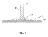
- a first end 231 of the rod 23 is connected to the central portion of the sucker 30.
- the adhesive layer 33 may include a first layer 331 and a second layer 333, in which the first layer 331 is adhesive.
- the first layer 331 and the second layer 333 are preferably integrated, for example, are formed in separate processes under different processing conditions.
- the second layer 333 wraps the first end 231 of the rod 23 and has an adequate strength.
- the handle 25 is pivoted to the second end 232 of the rod 23 via the pivot 27, and the outer housing 21 has a first slot 213 for the pivot 27 to pass therethrough.
- the pivot 27 is inserted sequentially through the handle 25, the first slot 213 of the outer housing 21 and the second end 232 of the rod 23.
- the handle 25 further has a fulcrum end 251.
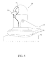
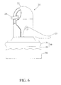
- the fulcrum end 251 When the user presses down the handle 25 to drive the holder 10 into the locked status, the fulcrum end 251 will lean against the outer housing 21 so that the outer housing 21 is pressed against the deformable body 31 at the edge thereof. Meanwhile, with the fulcrum end 251, the pivot 27 is lifted upwards by the handle 25 to slide upwards along the first slot 213 of the outer housing 21, thereby lifting the rod 23.
- the upward lifting of the rod 23 relative to the deformable body 31 will also lift the central portion of the sucker 30 synchronously while the rim 211 of the outer housing 21 still presses against the edge of the sucker 30 to fix the edge of the sucker 30.
- a low-pressure space is formed between the adhesive layer 33 and the object.
- the holder 10 further includes a connecting module 28 disposed on the locking module 20 for connection with a handheld electronic device (not shown).
- the connecting module 28 may be a fixed or an adjustable structure, e.g., a ball joint, a flexible pipe or the like, which allows for the easy adjustment of the displaying angle exhibited by the electronic device.
- the holder 10 may further include an elastic member 24, e.g., a spring, disposed over the rod 23, and when the handle 25 is driven into the locked status, the elastic member 24 will be compressed to store elastic potential energy. Once the handle 25 is released, the elastic potential energy of the elastic member 24 will be released to drive other elements including the outer housing 21 back to the unlocked original position.
- the adhesive layer 33 may further include a release member 335. After the handle 25 has been released by the user to drive the holder into the unlocked status, the release member 335 may be further operated by the user to make the air flowing into the low-pressure space, thereby separated the holder 10.
- the holder 10 further includes a deformable body 31.
- the force can be applied on the adhesive layer 33 with the deformable body 31 so that the sucker 30 is mounted on the surface of the object 50.
- the deformable body 31 can still force the adhesive layer 33 to be attached onto the non-flat surface.
- the edge portion of the sucker 30 can match and complement the curved surface of the object 50. Consequently, a low-pressure space can still be formed between the adhesive layer 33 and the surface of the object 50 even if the rim 211 of the outer housing 21 that is made of a hard material.
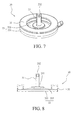
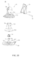
- FIGS. 7 and 8 are a perspective view of a sucker 30, and FIG 8 is a central cross-sectional view of the sucker 30 shown in FIG 7 .
- the deformable body 31 and the adhesive layer 33 are formed integrally.
- a hollow pad is formed on the edge of the second layer 333 and then is filled with a fluid or tiny particles to form the deformable body 31.
- the deformable body 31 and the adhesive layer 33 modularly form a sucker 30. This is provided as another approach, and the present application is not limited to this approach.
- the first layer 331 of the adhesive layer 33 may be made of an adhesive flexible material, for example, a viscose like material.
- the first layer 331 can be effectively attached onto the patterned surface of the object 50, so the holder 10 of the present embodiment is applicable to be mounted on the patterned surfaces, for example, dashboards and the like.
- the locking module 20 of the holder 10 of this embodiment further includes an inner shell 29 adapted to be received inside the outer housing 21.
- the inner shell 29 has a rim 291 and a second slot 293 for the pivot 27 to pass therethrough and slide therein.
- the open end of the inner shell 29 has a smaller rim 291, and when the rod 23 is lifted upwards and the inner shell 29 is, along with the outer housing 21, pressed downwards against the adhesive layer 33, this helps to limit the range of the low-pressure space and have it concentrated towards the central area of the adhesive layer 33. In this way, a larger contact area will be obtained between the adhesive layer 33 and the object 50 when the holder 10 is mounted onto the surface of the object 50, which makes it easier to maintain the low-pressure space. Hence, it is less likely for the holder to be separated even when being shaken by an external force, thereby further improving the suction stability thereof.
- the holder 60 includes a locking module 70, a rod 23 and an adhesive layer 83.
- the adhesive layer 83 has a central portion 831 and an edge portion 832.
- a first end 731 of the rod 23 is connected to the central portion of the adhesive layer.
- the locking module 70 which is disposed on the adhesive layer 83, is adapted to provide a force against the edge portion 832 of the adhesive layer 83 to attach the adhesive layer 83 onto the surface of the object, thereby mounting the holder 60 onto the object.
- the locking module 70 includes an outer housing 71 and a plurality of strip structures 715.
- the plurality of strip structures 715 are spaced from each other and extend from the outer housing 71 to thrust against the edge portion 832 of the adhesive layer 83.
- the strip structures 715 are formed as a deformable structure, so that when the object substantially has a non-flat surface contour, the strip structures 715 can adaptively deform to match the surface contour and apply the force to the edge portion 832 of the adhesive layer 83 evenly, thereby causing the deformation of the edge portion 832 along the surface contour.
- the locking module 70 further includes a handle 75 which is pivoted to the second end 732 of the rod 73 by the pivot 77.
- the handle 75 further has a fulcrum end 751.
- the fulcrum end 751 will lean against the outer housing 71 exactly so that the outer housing 71 is pressed against the edge portion 832 of the adhesive layer 83 via the strip structures 715.
- the pivot 77 is lifted upwards by the handle 75 to slide upwards along the first slot 713 of the outer housing 71, thereby lifting the rod 73. Consequently, a low-pressure space is formed between the adhesive layer 83 and the object.
- the adhesive layer 83 may also include a first layer and a second layer which are preferably formed integrally. The second layer wraps the first end 731 of the rod 73, while the first layer is adhesive to be mounted onto a patterned surface.
- the holder 60 further includes a connecting module 78 disposed on the locking module 70 for connection with a handheld electronic device (not shown).
- the holder 60 may also include an elastic member 74 and a release member 835, which are similar to those of the previous embodiments and thus will not be described again herein.
- this embodiment may also include an inner shell 79, which has a rim 791 and a second slot 793 for the pivot to pass therethrough.
- the inner shell 79 may be, along with the outer housing 71, pressed downwards against the adhesive layer 83 to have the low-pressure space concentrated towards the central portion 831, thereby improving the stability.
- the holder disclosed in the present application can apply a force evenly to the edge of the sucker. Accordingly, the holder of the present application may be used with various curved surfaces to provide a desirable attachment effect; and when an adhesive layer is adopted, the holder may further be mounted onto patterned surfaces. Moreover, for the holder of the present application, the range of the low-pressure region is shrunken and, therefore, the distance between the low-pressure region and the edge of the adhesive layer is enlarged so that when the holder is mounted onto a surface of an obj ect, it is easier to maintain the low-pressure space. Hence, it is less likely for the holder to be separated even when being shaken by an external force, thereby further improving the suction stability thereof.
Landscapes
- Engineering & Computer Science (AREA)
- General Engineering & Computer Science (AREA)
- Mechanical Engineering (AREA)
- Hooks, Suction Cups, And Attachment By Adhesive Means (AREA)
- Telephone Set Structure (AREA)
- Springs (AREA)
- Arrangement Or Mounting Of Propulsion Units For Vehicles (AREA)
Applications Claiming Priority (1)
| Application Number | Priority Date | Filing Date | Title |
|---|---|---|---|
| TW098114811A TWI401383B (zh) | 2009-05-05 | 2009-05-05 | 支架及其吸盤 |
Publications (2)
| Publication Number | Publication Date |
|---|---|
| EP2249048A1 true EP2249048A1 (fr) | 2010-11-10 |
| EP2249048B1 EP2249048B1 (fr) | 2011-04-13 |
Family
ID=41683298
Family Applications (1)
| Application Number | Title | Priority Date | Filing Date |
|---|---|---|---|
| EP10150662A Active EP2249048B1 (fr) | 2009-05-05 | 2010-01-13 | Support et ventouse correspondante |
Country Status (5)
| Country | Link |
|---|---|
| US (1) | US8876072B2 (fr) |
| EP (1) | EP2249048B1 (fr) |
| AT (1) | ATE505657T1 (fr) |
| DE (1) | DE602010000018D1 (fr) |
| TW (1) | TWI401383B (fr) |
Cited By (1)
| Publication number | Priority date | Publication date | Assignee | Title |
|---|---|---|---|---|
| CN104279408A (zh) * | 2013-07-01 | 2015-01-14 | 冠捷投资有限公司 | 支架总成 |
Families Citing this family (11)
| Publication number | Priority date | Publication date | Assignee | Title |
|---|---|---|---|---|
| US8282057B2 (en) * | 2010-04-27 | 2012-10-09 | Hung-Wei Lin | Sucker attachment device having direction adjustable function |
| KR101063058B1 (ko) * | 2010-10-28 | 2011-09-07 | 박민식 | 거치 대 용 기밀 부착 패드 |
| RU2587568C2 (ru) * | 2012-11-19 | 2016-06-20 | Чжуншань Тайли Хаузхолд Продактс Мэньюфэкчеринг Ко., Лтд. | Чашечная присоска с плоским каркасом |
| US9677598B2 (en) * | 2014-08-21 | 2017-06-13 | San Hao Rubber Company Ltd. | Pad structure of sucking disc |
| TWI537486B (zh) * | 2014-10-03 | 2016-06-11 | 群光電子股份有限公司 | 旋轉式吸盤結構 |
| TW201615328A (zh) * | 2014-10-21 | 2016-05-01 | Sportsman Corp | 固持夾具 |
| KR20160108112A (ko) | 2015-03-05 | 2016-09-19 | 주식회사 씨피씨 | 흡착판 |
| USD883370S1 (en) * | 2018-04-09 | 2020-05-05 | New Ideas Manufacturing LLC | Tripod head |
| USD894999S1 (en) * | 2018-10-12 | 2020-09-01 | Colorado Tripod Company | Tripod head |
| WO2020086085A1 (fr) * | 2018-10-25 | 2020-04-30 | Free-Free(USA) Inc | Ventouse |
| CN218528423U (zh) * | 2022-09-30 | 2023-02-28 | 宁波诺室设计有限公司 | 吸盘式挂钩 |
Citations (6)
| Publication number | Priority date | Publication date | Assignee | Title |
|---|---|---|---|---|
| EP0775462A2 (fr) * | 1995-11-27 | 1997-05-28 | Hokumei Co., Ltd. | Support et sa méthode de fixation |
| WO2005035999A1 (fr) * | 2003-10-11 | 2005-04-21 | Sense Good | Dispositif a vide |
| US20070120027A1 (en) * | 2005-11-28 | 2007-05-31 | Chang Ta S | Suction cup |
| US20070262217A1 (en) * | 2006-05-15 | 2007-11-15 | Leland Wang | Sucking disc apparatus |
| US20080224009A1 (en) | 2007-03-13 | 2008-09-18 | Soon Young Song | Adhesion device by holding low pressure |
| WO2008123692A1 (fr) * | 2007-04-05 | 2008-10-16 | Airfix Co., Ltd. | Appareil d'aspiration |
Family Cites Families (35)
| Publication number | Priority date | Publication date | Assignee | Title |
|---|---|---|---|---|
| US1840400A (en) * | 1930-03-28 | 1932-01-12 | Everedy Company | Support |
| US2657893A (en) * | 1951-04-09 | 1953-11-03 | Puckert Esca William | Pneumatic suction device |
| US2968460A (en) * | 1959-05-18 | 1961-01-17 | Laurence W Van Dusen | Vacuum mounting device |
| US3051117A (en) * | 1960-06-21 | 1962-08-28 | Jr Omer Benjamin Hunter | Vacuum anchor |
| US3180604A (en) * | 1963-08-02 | 1965-04-27 | Boyd F Hammer | Adjustable support means for a cassette and like devices |
| US3976274A (en) * | 1975-05-27 | 1976-08-24 | The United States Of America As Represented By The Secretary Of The Navy | Permanent attachment for suction cups |
| DE2553486A1 (de) * | 1975-11-28 | 1977-06-16 | Ever Clean Gmbh | Vibrationsdaempfer fuer windschutzscheiben |
| US4356989A (en) * | 1980-06-30 | 1982-11-02 | Ireland Jack W | Resilient suction cup with soft pliable sealing gasket |
| US5133524A (en) * | 1991-02-11 | 1992-07-28 | Liu Bao Shen | Suction cup device |
| US6234435B1 (en) * | 1999-10-13 | 2001-05-22 | Ta Kuang Yeh | Sucking disk support |
| US7575208B2 (en) * | 2003-10-27 | 2009-08-18 | Yung-Huei Lan | Holding device with a securing sheet for mounting onto a wall |
| US20020175250A1 (en) * | 2001-05-23 | 2002-11-28 | Bing-Tson Lian | Fixation seat capable of being attached firmly to wall |
| US6478271B1 (en) * | 2001-08-07 | 2002-11-12 | Free-Free Industrial Corporation | Mounting sucker |
| HK1053581A2 (en) * | 2002-08-01 | 2003-10-10 | 金峰塑胶制品有限公司 | Suction-adhesive device |
| CA2565469C (fr) * | 2004-05-03 | 2013-04-16 | Poetters, Gert | Dispositif de maintien par succion |
| US7007908B2 (en) * | 2004-06-23 | 2006-03-07 | Wen-Feng Tsay | Sucking disk type hanging pole |
| US20070090234A1 (en) * | 2005-05-31 | 2007-04-26 | Supa Technology Co., Ltd. | Multi-function fastening stand |
| US20070018064A1 (en) * | 2005-07-20 | 2007-01-25 | Chin-Yang Wang | Holder |
| DE102005047809A1 (de) * | 2005-10-05 | 2007-04-12 | Harald Richter | Saugfuß für Geräteträger oder dergleichen |
| DE102005046869B4 (de) * | 2005-09-30 | 2008-06-12 | Harald Richter | Gerätehalter-Saugfuß mit Kolben-Zylinder-Anordnung |
| CN101316531B (zh) * | 2005-11-28 | 2010-09-22 | 金春东 | 多用途吸盘 |
| US20070152119A1 (en) * | 2006-01-04 | 2007-07-05 | Chin-Yang Wang | Bracket apparatus |
| WO2007117130A1 (fr) * | 2006-04-12 | 2007-10-18 | Tomtom International B.V. | Monture comportant une ventouse a aspiration |
| JP4305670B2 (ja) | 2006-04-20 | 2009-07-29 | ソニー株式会社 | 吸盤 |
| TWM298663U (en) * | 2006-04-24 | 2006-10-01 | Comart Corp | Sucking disk assembly |
| TWI307385B (en) * | 2006-06-01 | 2009-03-11 | Mitac Int Corp | Suction cup structure |
| US7516926B2 (en) * | 2006-06-16 | 2009-04-14 | Comart Corporation | Suction disc unit |
| ATE479026T1 (de) * | 2006-07-12 | 2010-09-15 | Bury Sp Zoo | Saugnapfvorrichtung, insbesondere für die windschutzscheibe eines kraftfahrzeugs |
| JP2008051296A (ja) * | 2006-08-28 | 2008-03-06 | Sony Corp | 吸盤 |
| JP2008089088A (ja) * | 2006-10-02 | 2008-04-17 | Sony Corp | 連結構造およびジョイント |
| CN101174477A (zh) | 2006-10-31 | 2008-05-07 | 佛山市顺德区顺达电脑厂有限公司 | 两用型车架组合 |
| JP4973262B2 (ja) * | 2007-03-20 | 2012-07-11 | ソニー株式会社 | 吸盤および吸盤装置 |
| DE102007057889A1 (de) * | 2007-11-29 | 2009-06-04 | Shu-Pei Huang | Saugnapfbefestiger |
| TWI347408B (en) * | 2008-07-16 | 2011-08-21 | Wistron Neweb Corp | Suction cup structure |
| GB2465189B (en) * | 2008-11-10 | 2012-06-06 | Eagle Fan | Structure for a suction device |
-
2009
- 2009-05-05 TW TW098114811A patent/TWI401383B/zh active
-
2010
- 2010-01-11 US US12/685,071 patent/US8876072B2/en active Active
- 2010-01-13 DE DE602010000018T patent/DE602010000018D1/de active Active
- 2010-01-13 AT AT10150662T patent/ATE505657T1/de not_active IP Right Cessation
- 2010-01-13 EP EP10150662A patent/EP2249048B1/fr active Active
Patent Citations (6)
| Publication number | Priority date | Publication date | Assignee | Title |
|---|---|---|---|---|
| EP0775462A2 (fr) * | 1995-11-27 | 1997-05-28 | Hokumei Co., Ltd. | Support et sa méthode de fixation |
| WO2005035999A1 (fr) * | 2003-10-11 | 2005-04-21 | Sense Good | Dispositif a vide |
| US20070120027A1 (en) * | 2005-11-28 | 2007-05-31 | Chang Ta S | Suction cup |
| US20070262217A1 (en) * | 2006-05-15 | 2007-11-15 | Leland Wang | Sucking disc apparatus |
| US20080224009A1 (en) | 2007-03-13 | 2008-09-18 | Soon Young Song | Adhesion device by holding low pressure |
| WO2008123692A1 (fr) * | 2007-04-05 | 2008-10-16 | Airfix Co., Ltd. | Appareil d'aspiration |
Cited By (1)
| Publication number | Priority date | Publication date | Assignee | Title |
|---|---|---|---|---|
| CN104279408A (zh) * | 2013-07-01 | 2015-01-14 | 冠捷投资有限公司 | 支架总成 |
Also Published As
| Publication number | Publication date |
|---|---|
| TW201040431A (en) | 2010-11-16 |
| EP2249048B1 (fr) | 2011-04-13 |
| DE602010000018D1 (de) | 2011-05-26 |
| ATE505657T1 (de) | 2011-04-15 |
| US8876072B2 (en) | 2014-11-04 |
| US20100282928A1 (en) | 2010-11-11 |
| TWI401383B (zh) | 2013-07-11 |
Similar Documents
| Publication | Publication Date | Title |
|---|---|---|
| US8876072B2 (en) | Holder and sucker thereof | |
| EP2249074B1 (fr) | Support | |
| US7661648B2 (en) | Sucker device for a fixing support | |
| US7219867B2 (en) | Mount assembly for electronic devices | |
| EP3429085B1 (fr) | Appareil pour monter un dispositif mobile sur une automobile | |
| US7226026B2 (en) | Suction device | |
| US8480044B2 (en) | Omni-direction rotatable dual-cup suction device | |
| USD581905S1 (en) | Audio and docking station for a handheld electronic device | |
| US8919712B2 (en) | Sucker assembly having a better attachment effect | |
| US20070138358A1 (en) | Mechanism for fastening a pivotal support in any derection | |
| JP4666519B2 (ja) | シート貼付装置 | |
| EP1721783B1 (fr) | Dispositif de retenue à ventouse | |
| EP2856900A1 (fr) | Accessoire multifonctions pour dispositif portable | |
| EP2085302A3 (fr) | Selle et dispositif d'aération de celle-ci | |
| KR200476134Y1 (ko) | 차량용 모바일 기기의 장착 장치 | |
| CN204124071U (zh) | 车载平板电子设备支架 | |
| US20090261219A1 (en) | On-vehicle holder of a portable electronic display device | |
| EP1850044A3 (fr) | Collier de serrage pour une colonne montante | |
| US20140124556A1 (en) | Mobile Electronic Device Holder | |
| US20130292538A1 (en) | Ergonomic device holder | |
| JP2007154933A (ja) | 吸盤 | |
| EP1923996A3 (fr) | Dispositif à onde acoustique de surface | |
| WO2009117865A1 (fr) | Dispositif de succion pour support de fixation | |
| KR100815498B1 (ko) | 차량 거치대 | |
| JP2011040532A (ja) | 吸着加圧コレット |
Legal Events
| Date | Code | Title | Description |
|---|---|---|---|
| PUAI | Public reference made under article 153(3) epc to a published international application that has entered the european phase |
Free format text: ORIGINAL CODE: 0009012 |
|
| 17P | Request for examination filed |
Effective date: 20100113 |
|
| AK | Designated contracting states |
Kind code of ref document: A1 Designated state(s): AT BE BG CH CY CZ DE DK EE ES FI FR GB GR HR HU IE IS IT LI LT LU LV MC MK MT NL NO PL PT RO SE SI SK SM TR |
|
| GRAP | Despatch of communication of intention to grant a patent |
Free format text: ORIGINAL CODE: EPIDOSNIGR1 |
|
| RIC1 | Information provided on ipc code assigned before grant |
Ipc: F16B 47/00 20060101AFI20101126BHEP |
|
| GRAS | Grant fee paid |
Free format text: ORIGINAL CODE: EPIDOSNIGR3 |
|
| GRAA | (expected) grant |
Free format text: ORIGINAL CODE: 0009210 |
|
| AK | Designated contracting states |
Kind code of ref document: B1 Designated state(s): AT BE BG CH CY CZ DE DK EE ES FI FR GB GR HR HU IE IS IT LI LT LU LV MC MK MT NL NO PL PT RO SE SI SK SM TR |
|
| REG | Reference to a national code |
Ref country code: GB Ref legal event code: FG4D |
|
| REG | Reference to a national code |
Ref country code: CH Ref legal event code: EP |
|
| REG | Reference to a national code |
Ref country code: IE Ref legal event code: FG4D |
|
| REF | Corresponds to: |
Ref document number: 602010000018 Country of ref document: DE Date of ref document: 20110526 Kind code of ref document: P |
|
| REG | Reference to a national code |
Ref country code: DE Ref legal event code: R096 Ref document number: 602010000018 Country of ref document: DE Effective date: 20110526 |
|
| REG | Reference to a national code |
Ref country code: NL Ref legal event code: T3 |
|
| LTIE | Lt: invalidation of european patent or patent extension |
Effective date: 20110413 |
|
| PG25 | Lapsed in a contracting state [announced via postgrant information from national office to epo] |
Ref country code: LT Free format text: LAPSE BECAUSE OF FAILURE TO SUBMIT A TRANSLATION OF THE DESCRIPTION OR TO PAY THE FEE WITHIN THE PRESCRIBED TIME-LIMIT Effective date: 20110413 Ref country code: SE Free format text: LAPSE BECAUSE OF FAILURE TO SUBMIT A TRANSLATION OF THE DESCRIPTION OR TO PAY THE FEE WITHIN THE PRESCRIBED TIME-LIMIT Effective date: 20110413 Ref country code: PT Free format text: LAPSE BECAUSE OF FAILURE TO SUBMIT A TRANSLATION OF THE DESCRIPTION OR TO PAY THE FEE WITHIN THE PRESCRIBED TIME-LIMIT Effective date: 20110816 Ref country code: HR Free format text: LAPSE BECAUSE OF FAILURE TO SUBMIT A TRANSLATION OF THE DESCRIPTION OR TO PAY THE FEE WITHIN THE PRESCRIBED TIME-LIMIT Effective date: 20110413 Ref country code: NO Free format text: LAPSE BECAUSE OF FAILURE TO SUBMIT A TRANSLATION OF THE DESCRIPTION OR TO PAY THE FEE WITHIN THE PRESCRIBED TIME-LIMIT Effective date: 20110713 |
|
| PG25 | Lapsed in a contracting state [announced via postgrant information from national office to epo] |
Ref country code: ES Free format text: LAPSE BECAUSE OF FAILURE TO SUBMIT A TRANSLATION OF THE DESCRIPTION OR TO PAY THE FEE WITHIN THE PRESCRIBED TIME-LIMIT Effective date: 20110724 Ref country code: CY Free format text: LAPSE BECAUSE OF FAILURE TO SUBMIT A TRANSLATION OF THE DESCRIPTION OR TO PAY THE FEE WITHIN THE PRESCRIBED TIME-LIMIT Effective date: 20110413 Ref country code: BE Free format text: LAPSE BECAUSE OF FAILURE TO SUBMIT A TRANSLATION OF THE DESCRIPTION OR TO PAY THE FEE WITHIN THE PRESCRIBED TIME-LIMIT Effective date: 20110413 Ref country code: SI Free format text: LAPSE BECAUSE OF FAILURE TO SUBMIT A TRANSLATION OF THE DESCRIPTION OR TO PAY THE FEE WITHIN THE PRESCRIBED TIME-LIMIT Effective date: 20110413 Ref country code: FI Free format text: LAPSE BECAUSE OF FAILURE TO SUBMIT A TRANSLATION OF THE DESCRIPTION OR TO PAY THE FEE WITHIN THE PRESCRIBED TIME-LIMIT Effective date: 20110413 Ref country code: AT Free format text: LAPSE BECAUSE OF FAILURE TO SUBMIT A TRANSLATION OF THE DESCRIPTION OR TO PAY THE FEE WITHIN THE PRESCRIBED TIME-LIMIT Effective date: 20110413 Ref country code: LV Free format text: LAPSE BECAUSE OF FAILURE TO SUBMIT A TRANSLATION OF THE DESCRIPTION OR TO PAY THE FEE WITHIN THE PRESCRIBED TIME-LIMIT Effective date: 20110413 Ref country code: GR Free format text: LAPSE BECAUSE OF FAILURE TO SUBMIT A TRANSLATION OF THE DESCRIPTION OR TO PAY THE FEE WITHIN THE PRESCRIBED TIME-LIMIT Effective date: 20110714 Ref country code: IS Free format text: LAPSE BECAUSE OF FAILURE TO SUBMIT A TRANSLATION OF THE DESCRIPTION OR TO PAY THE FEE WITHIN THE PRESCRIBED TIME-LIMIT Effective date: 20110813 |
|
| PG25 | Lapsed in a contracting state [announced via postgrant information from national office to epo] |
Ref country code: EE Free format text: LAPSE BECAUSE OF FAILURE TO SUBMIT A TRANSLATION OF THE DESCRIPTION OR TO PAY THE FEE WITHIN THE PRESCRIBED TIME-LIMIT Effective date: 20110413 Ref country code: CZ Free format text: LAPSE BECAUSE OF FAILURE TO SUBMIT A TRANSLATION OF THE DESCRIPTION OR TO PAY THE FEE WITHIN THE PRESCRIBED TIME-LIMIT Effective date: 20110413 |
|
| PLBE | No opposition filed within time limit |
Free format text: ORIGINAL CODE: 0009261 |
|
| STAA | Information on the status of an ep patent application or granted ep patent |
Free format text: STATUS: NO OPPOSITION FILED WITHIN TIME LIMIT |
|
| PG25 | Lapsed in a contracting state [announced via postgrant information from national office to epo] |
Ref country code: SK Free format text: LAPSE BECAUSE OF FAILURE TO SUBMIT A TRANSLATION OF THE DESCRIPTION OR TO PAY THE FEE WITHIN THE PRESCRIBED TIME-LIMIT Effective date: 20110413 Ref country code: PL Free format text: LAPSE BECAUSE OF FAILURE TO SUBMIT A TRANSLATION OF THE DESCRIPTION OR TO PAY THE FEE WITHIN THE PRESCRIBED TIME-LIMIT Effective date: 20110413 |
|
| 26N | No opposition filed |
Effective date: 20120116 |
|
| REG | Reference to a national code |
Ref country code: DE Ref legal event code: R097 Ref document number: 602010000018 Country of ref document: DE Effective date: 20120116 |
|
| PG25 | Lapsed in a contracting state [announced via postgrant information from national office to epo] |
Ref country code: IT Free format text: LAPSE BECAUSE OF FAILURE TO SUBMIT A TRANSLATION OF THE DESCRIPTION OR TO PAY THE FEE WITHIN THE PRESCRIBED TIME-LIMIT Effective date: 20110413 |
|
| PG25 | Lapsed in a contracting state [announced via postgrant information from national office to epo] |
Ref country code: MC Free format text: LAPSE BECAUSE OF NON-PAYMENT OF DUE FEES Effective date: 20120131 |
|
| REG | Reference to a national code |
Ref country code: IE Ref legal event code: MM4A |
|
| PG25 | Lapsed in a contracting state [announced via postgrant information from national office to epo] |
Ref country code: IE Free format text: LAPSE BECAUSE OF NON-PAYMENT OF DUE FEES Effective date: 20120113 |
|
| PG25 | Lapsed in a contracting state [announced via postgrant information from national office to epo] |
Ref country code: MK Free format text: LAPSE BECAUSE OF FAILURE TO SUBMIT A TRANSLATION OF THE DESCRIPTION OR TO PAY THE FEE WITHIN THE PRESCRIBED TIME-LIMIT Effective date: 20110413 |
|
| PG25 | Lapsed in a contracting state [announced via postgrant information from national office to epo] |
Ref country code: BG Free format text: LAPSE BECAUSE OF FAILURE TO SUBMIT A TRANSLATION OF THE DESCRIPTION OR TO PAY THE FEE WITHIN THE PRESCRIBED TIME-LIMIT Effective date: 20110713 |
|
| PG25 | Lapsed in a contracting state [announced via postgrant information from national office to epo] |
Ref country code: MT Free format text: LAPSE BECAUSE OF FAILURE TO SUBMIT A TRANSLATION OF THE DESCRIPTION OR TO PAY THE FEE WITHIN THE PRESCRIBED TIME-LIMIT Effective date: 20110413 |
|
| PG25 | Lapsed in a contracting state [announced via postgrant information from national office to epo] |
Ref country code: TR Free format text: LAPSE BECAUSE OF FAILURE TO SUBMIT A TRANSLATION OF THE DESCRIPTION OR TO PAY THE FEE WITHIN THE PRESCRIBED TIME-LIMIT Effective date: 20110413 |
|
| PG25 | Lapsed in a contracting state [announced via postgrant information from national office to epo] |
Ref country code: LU Free format text: LAPSE BECAUSE OF NON-PAYMENT OF DUE FEES Effective date: 20120113 Ref country code: SM Free format text: LAPSE BECAUSE OF FAILURE TO SUBMIT A TRANSLATION OF THE DESCRIPTION OR TO PAY THE FEE WITHIN THE PRESCRIBED TIME-LIMIT Effective date: 20110413 |
|
| PG25 | Lapsed in a contracting state [announced via postgrant information from national office to epo] |
Ref country code: HU Free format text: LAPSE BECAUSE OF FAILURE TO SUBMIT A TRANSLATION OF THE DESCRIPTION OR TO PAY THE FEE WITHIN THE PRESCRIBED TIME-LIMIT Effective date: 20100113 |
|
| REG | Reference to a national code |
Ref country code: CH Ref legal event code: PL |
|
| PG25 | Lapsed in a contracting state [announced via postgrant information from national office to epo] |
Ref country code: CH Free format text: LAPSE BECAUSE OF NON-PAYMENT OF DUE FEES Effective date: 20140131 Ref country code: LI Free format text: LAPSE BECAUSE OF NON-PAYMENT OF DUE FEES Effective date: 20140131 |
|
| REG | Reference to a national code |
Ref country code: FR Ref legal event code: PLFP Year of fee payment: 7 |
|
| REG | Reference to a national code |
Ref country code: FR Ref legal event code: PLFP Year of fee payment: 8 |
|
| REG | Reference to a national code |
Ref country code: FR Ref legal event code: PLFP Year of fee payment: 9 |
|
| P01 | Opt-out of the competence of the unified patent court (upc) registered |
Effective date: 20230602 |
|
| PGFP | Annual fee paid to national office [announced via postgrant information from national office to epo] |
Ref country code: NL Payment date: 20241214 Year of fee payment: 16 |
|
| PGFP | Annual fee paid to national office [announced via postgrant information from national office to epo] |
Ref country code: GB Payment date: 20241205 Year of fee payment: 16 |
|
| PGFP | Annual fee paid to national office [announced via postgrant information from national office to epo] |
Ref country code: FR Payment date: 20241209 Year of fee payment: 16 |
|
| PGFP | Annual fee paid to national office [announced via postgrant information from national office to epo] |
Ref country code: DE Payment date: 20241203 Year of fee payment: 16 |