EP2249064A2 - Actionneur hydraulique pour véhicule - Google Patents
Actionneur hydraulique pour véhicule Download PDFInfo
- Publication number
- EP2249064A2 EP2249064A2 EP10161709A EP10161709A EP2249064A2 EP 2249064 A2 EP2249064 A2 EP 2249064A2 EP 10161709 A EP10161709 A EP 10161709A EP 10161709 A EP10161709 A EP 10161709A EP 2249064 A2 EP2249064 A2 EP 2249064A2
- Authority
- EP
- European Patent Office
- Prior art keywords
- annular
- piston
- hydraulic actuator
- oil
- spacer
- Prior art date
- Legal status (The legal status is an assumption and is not a legal conclusion. Google has not performed a legal analysis and makes no representation as to the accuracy of the status listed.)
- Granted
Links
- 125000006850 spacer group Chemical group 0.000 claims abstract description 85
- 230000002093 peripheral effect Effects 0.000 claims abstract description 19
- 238000004891 communication Methods 0.000 claims abstract description 9
- 239000012530 fluid Substances 0.000 claims abstract description 9
- 230000001105 regulatory effect Effects 0.000 claims abstract description 8
- 239000003921 oil Substances 0.000 claims description 54
- 238000012856 packing Methods 0.000 claims description 18
- 239000010720 hydraulic oil Substances 0.000 claims description 8
- 230000005540 biological transmission Effects 0.000 description 5
- 239000000463 material Substances 0.000 description 3
- 238000007789 sealing Methods 0.000 description 3
- XEEYBQQBJWHFJM-UHFFFAOYSA-N Iron Chemical compound [Fe] XEEYBQQBJWHFJM-UHFFFAOYSA-N 0.000 description 2
- 229920003051 synthetic elastomer Polymers 0.000 description 2
- 239000005061 synthetic rubber Substances 0.000 description 2
- 238000010276 construction Methods 0.000 description 1
- 229910052742 iron Inorganic materials 0.000 description 1
- 238000004519 manufacturing process Methods 0.000 description 1
- 238000000034 method Methods 0.000 description 1
- 238000012986 modification Methods 0.000 description 1
- 230000004048 modification Effects 0.000 description 1
- 239000004810 polytetrafluoroethylene Substances 0.000 description 1
- 229920001343 polytetrafluoroethylene Polymers 0.000 description 1
- 239000011347 resin Substances 0.000 description 1
- 229920005989 resin Polymers 0.000 description 1
Images

Classifications
-
- F—MECHANICAL ENGINEERING; LIGHTING; HEATING; WEAPONS; BLASTING
- F15—FLUID-PRESSURE ACTUATORS; HYDRAULICS OR PNEUMATICS IN GENERAL
- F15B—SYSTEMS ACTING BY MEANS OF FLUIDS IN GENERAL; FLUID-PRESSURE ACTUATORS, e.g. SERVOMOTORS; DETAILS OF FLUID-PRESSURE SYSTEMS, NOT OTHERWISE PROVIDED FOR
- F15B15/00—Fluid-actuated devices for displacing a member from one position to another; Gearing associated therewith
- F15B15/20—Other details, e.g. assembly with regulating devices
- F15B15/24—Other details, e.g. assembly with regulating devices for restricting the stroke
-
- F—MECHANICAL ENGINEERING; LIGHTING; HEATING; WEAPONS; BLASTING
- F16—ENGINEERING ELEMENTS AND UNITS; GENERAL MEASURES FOR PRODUCING AND MAINTAINING EFFECTIVE FUNCTIONING OF MACHINES OR INSTALLATIONS; THERMAL INSULATION IN GENERAL
- F16H—GEARING
- F16H61/00—Control functions within control units of change-speed- or reversing-gearings for conveying rotary motion ; Control of exclusively fluid gearing, friction gearing, gearings with endless flexible members or other particular types of gearing
- F16H61/26—Generation or transmission of movements for final actuating mechanisms
- F16H61/28—Generation or transmission of movements for final actuating mechanisms with at least one movement of the final actuating mechanism being caused by a non-mechanical force, e.g. power-assisted
- F16H61/30—Hydraulic or pneumatic motors or related fluid control means therefor
Definitions
- the invention relates to a hydraulic actuator for a vehicle and, more particularly, to a technique for reducing the size of the hydraulic actuator in the axial direction.
- such a hydraulic actuator for a vehicle, which is used for assisting steering operating force, or the like.
- a hydraulic actuator includes a cylinder body 72 having a cylinder bore 70, an output rod 76 having a piston 74 slidably fitted in the cylinder bore 70, rod covers 80 that allow the output rod 76 to slidably extend therethrough in order to seal the openings of the cylinder bore 70 of the cylinder body 72 in an oil tight manner and that are fitted to the openings in a state where the output rod 76 is sealed by packings 78.
- Hydraulic pressures supplied to a pair of oil chambers 82 partitioned by the piston 74 are controlled to generate a differential pressure between the pair of oil chambers 82, thus driving the output rod 76.
- the above hydraulic actuator is, for example, described in Japanese Patent Application Publication No. 08-230703 ( JP-A-08-230703 ), Japanese Patent Application Publication No. 08-183469 ( JP-A-08-183469 ) and Japanese Patent Application Publication No. 2002-019628 ( JP-A-2002-019628 ).
- Such a hydraulic actuator for a vehicle has a relatively large axial size, so it is desired to further reduce the size in order to improve mountability to the vehicle.
- the hydraulic actuator 68 for a vehicle is provided with a space S having an axial size larger than the diameter D of an oil passage 84 at a location beyond the stroke of the rod cover-side piston 74 in the oil chamber 82 so as not to cause interference between the oil chamber 84, formed in the cylinder body 72 to supply hydraulic oil into the oil chamber 82 of the cylinder body 72, and the piston 74 that reciprocally moves in the cylinder body 72. Therefore, the space S becomes a bottleneck for reducing the axial size of the hydraulic actuator for a vehicle.
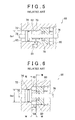
- FIG. 6 another hydraulic actuator 88 for a vehicle is suggested.
- the hydraulic actuator 88 has a structure such that a petaloid spacer 86 is provided instead of the space S, and the stroke is regulated in such a manner that the piston 74 is brought into contact with the spacer 86.
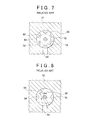
- the spacer 86 has a thickness equivalent to the diameter D of the oil passage 84, and, as shown in FIG. 7 that is a cross-sectional view taken along the line VII-VII in FIG. 6 and FIG. 8 that is a cross-sectional view taken along the line VIII-VIII in FIG. 6 , a plurality of protrusions 90 parallel to the axial direction are provided at equiangular intervals in the circumferential direction.
- each protrusion 90 in the circumferential direction is smaller than the diameter D of the oil passage 84, the root diameter T between the adjacent protrusions 90 is smaller than the outside diameter of the piston 74, that is, the inside diameter Dp2 of the cylinder bore 70, and is larger than the outside diameter of the packing 78.
- the inside diameter Dp2 of the cylinder bore 70 and the outside diameter Dh2 of the rod cover 80 in FIG. 6 are respectively larger than the inside diameter Dp1 of the cylinder bore 70 and the outside diameter Dh1 of the rod cover 80 of the hydraulic actuator 68 in FIG. 5 .
- the hydraulic actuator 88 for a vehicle shown in FIG. 6 uses the spacer 86 having a smaller axial size than the spacer S in FIG. 5 .
- the axial size is reduced because the hydraulic actuator 88 has a structure such that the stroke is regulated by bringing the piston 74 into contact with the spacer 86.
- the root diameter T between the adjacent protrusions 90 needs to be larger than the outside diameter of the packing 78, which is determined on the basis of the diameter of the output rod 76, and the outside diameter of the piston 74 needs to be larger than the root diameter T between the adjacent protrusions 90.
- the size of the hydraulic actuator 88 for a vehicle is not radially reduced.
- hydraulic pressure acts only on part of the area of the piston 74 when the hydraulic pressure is applied in a direction to separate the piston 74 from the spacer 86, so the response is poor.
- the moment occurs in the piston 74 to cause resistance or unbalanced wear of a bushing or packing.
- the protrusions 90 of the spacer 86 may block part of the opening of the oil passage 84, so a desired flow rate may not be obtained, and variations in flow rate and shift time occur.
- the spacer 86 is interposed between a piston body 72 and the rod cover 80; however, there is a permissible clearance in manufacturing, so a gap easily occurs between the spacer 86 and the rod cover 80. This may cause the packing 78 to come off from the rod cover 80 or cause the spacer 86 to damage the outer peripheral portion of the packing 78 when pressed by the piston 74 to thereby decrease sealing performance.
- the invention provides a hydraulic actuator for a vehicle, which is small in size in the radial direction, has a high response, is easy to assemble and can obtain durability of a bushing and a packing.
- An aspect of the invention provides a hydraulic actuator for a vehicle.
- the hydraulic actuator includes: a cylinder body that has a cylinder bore having a center portion and open portions that are larger in diameter than the center portion; an output rod that has a piston slidably fitted in the cylinder bore; rod covers that allow the output rod to slidably extend therethrough and that are fitted in the respective open portions of the cylinder body in a state where the output rod is sealed by packings in order to seal the cylinder bore inside the cylinder body in an oil tight manner; oil passages that respectively supply hydraulic oil to a pair of oil chambers of the cylinder bore, the pair of oil chambers being partitioned by the piston; and an annular spacer, wherein annular grooves each having an axial size larger than the diameter of a corresponding one of the oil passages are formed on outer peripheral surfaces of the respective annular spacers, a plurality of radial grooves that provide fluid communication between the annular grooves and the corresponding oil chambers are formed in the annular spacers at
- the annular grooves each having an axial size larger than the diameter of a corresponding one of the oil passages are formed on the outer peripheral surfaces of the respective annular spacers, and the plurality of radial grooves that provide fluid communication between the annular grooves and the corresponding oil chambers are formed in the annular spacers at sides adjacent to the piston.
- the annular spacers are fitted in between the rod covers and the center portion of the cylinder bore, and the stroke of the piston is regulated in such a manner that the piston contacts with any one of the annular spacers. For this reason, as hydraulic oil is supplied from any one of the oil passages, hydraulic pressure is applied to the piston via the plurality of radial grooves.
- the annular grooves each may have a cross-sectional area larger than the cross-sectional area of a corresponding one of the oil passages.
- the annular grooves each have a cross-sectional area that is larger than the cross-sectional area of a corresponding one of the oil passages.
- the annular spacers each may include a flange portion that radially protrudes from the outer peripheral surface of the annular spacer at a side adjacent to a corresponding one of the rod covers and a flat end surface that faces a corresponding one of the rod covers.
- the spacers each include the flange portion that radially protrudes from the outer peripheral surface of the spacer at a side adjacent to a corresponding one of the rod covers and a flat end surface that faces a corresponding one of the rod covers.
- pressure from the oil passage acts on the flange portion to press the spacer against the rod cover.
- it is hard to form a gap between the spacer and the rod cover. This eliminates a situation that the packing comes off from the rod cover or the packing is damaged to decrease sealing performance.
- the annular spacers may be respectively provided at both sides of the center portion so as to face each other via the center portion.
- the plurality of radial grooves may be formed to radially extend through each annular spacer so as to open at an end surface of the annular spacer adjacent to the piston.
- FIG. 1 shows a relevant portion of a hydraulic actuator 10 for a vehicle.
- the hydraulic actuator 10 is used for shift operation or select operation in a parallel shaft constant mesh transmission that is arranged in a power transmission path of the vehicle.
- the hydraulic actuator 10 includes a cylinder body 14 through which a circular cylindrical cylinder bore 12 is formed.
- the cylinder body 14 is integrally formed from part of a housing of the parallel shaft constant mesh transmission.
- the cylinder bore 12 has a center portion 12a and a pair of open portions 12bL and 12bR each having a diameter larger than that of the center portion 12a, so the cylinder bore 12 is formed in a stepped hole shape.
- the hydraulic actuator 10 includes an output rod 18 and through holes 20L and 20R.
- the output rod 18 integrally has a piston 16 slidably fitted in the center portion 12a of the cylinder bore 12.
- the through holes 20L and 20R allow the output rod 18 to slidably extend therethrough.
- the hydraulic actuator 10 includes a pair of thick short cylindrical rod covers 22L and 22R and packings 24L and 24R.
- the pair of rod covers 22L and 22R are respectively fitted in the open portions 12bL and 12bR of the cylinder bore 12 of the cylinder body 14 in an oil tight manner.
- the packings 24L and 24R are respectively fitted to large-diameter portions 20aL and 20aR at sides adjacent to the piston 16 in the respective through holes 20L and 20R of the rod covers 22L and 22R in order to seal gaps between the rod covers 22L and 22R and the output rod 18 in an oil tight manner.
- the packings 24L and 24R are so-called oil seals made of, for example, synthetic rubber, and slidably seal gaps from the output rod 18 in an oil tight manner.
- seal members 26L and 26R such as synthetic rubber O rings, are fitted in outer peripheral grooves formed on outer peripheral surfaces of the rod covers 22L and 22R, and gaps between the rod covers 22L and 22R and the open portions of the cylinder bore 12 are sealed in an oil tight manner.
- Accommodating holes 20bL and 20bR provided for the through holes 20L and 20R of the rod covers 22L and 22R at sides opposite to the sides at which the piston 16 is provided.
- Bushings 28L and 28R are respectively fitted in the accommodating holes 20bL and 20bR in order to support the weight of the output rod 18 and a load applied to the output rod 18.
- the bushings 28L and 28R are made of iron-based material, and the sliding portions of the bushings 28L and 28R are coated with PTFE material (resin bimetal material).
- the rod covers 22L and 22R are prevented from coming off by snap rings 30L and 30R and fixed in the open portions 12bL and 12bR.
- the snap rings 30L and 30R are fitted in the inner peripheral grooves formed at portions adjacent to the open edges of the open portions 12bL and 12bR of the cylinder bore 12.
- the center portion 12a of the cylinder bore 12 is partitioned into a pair of oil chambers 32L and 32R by the piston 16 fitted therein.
- the cylinder body 14 has a pair of oil passages 34L and 34R that are respectively in fluid communication with the pair of oil chambers 32L and 32R.
- the pair of oil passages 34L and 34R are respectively open at the inner peripheral surfaces of the open portions 12bL and 12bR of the cylinder bore 12 and located adjacent to the center portion 12a of the cylinder bore 12 with respect to the rod covers 22L and 22R.
- a pair of spacers 36L and 36R are respectively fitted in the open portions 12bL and 12bR of the cylinder bore 12 and located adjacent to the center portion 12a of the cylinder bore 12 with respect to the rod covers 22L and 22R.
- the stroke end of the piston 16 is regulated in such a manner that any one of the pair of spacers 36L and 36R contacts with the piston 16.
- the pair of spacers 36L and 36R are fixedly interposed between center portion 12a side ends of the open portions 12bL and 12bR and the rod covers 22L and 22R.
- the pair of spacers 36L and 36R are formed similarly to each other, so the configuration of the spacer 36R will be typically described. Note that only reference numerals are shown in parentheses for the configuration of the spacer 36L, corresponding to the configuration of the spacer 36R.
- the spacer 36R (36L) is an annular thick disk plate that has a through hole 38R (38L) having a slightly larger diameter than the diameter of the output rod 18.
- An annular groove 40R (40L) is formed on the outer peripheral surface of the spacer 36R (36L).
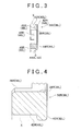
- the annular groove 40R (40L) has an axial size (width) w larger than the opening diameter d of the oil passage 34R (34L).
- the annular groove 40R (40L) is open at an end surface adjacent to the piston 16.
- the spacer 36R (36L) has a flange portion 42R (42L) and a flat end surface 44R (44L).
- the flange portion 42R (42L) radially protrudes from the outer peripheral surface of the spacer 36R (36L) adjacent to the rod cover 22R (22L) .
- the end surface 44R (44L) is provided adjacent to the rod cover 22R (22L) and is able to closely contact with and face the rod cover 22R (22L).
- the spacer 36R (36L) includes a plurality of (four in the present embodiment) radial grooves 46R (46L) that are formed to radially extend therethrough so as to open at an end surface adjacent to the piston 16 in order to provide fluid communication between the annular groove 40R (40L) and the oil chamber 32R (32L).
- fluid communication is provided between the oil passage 34R (34L) and the oil chamber 32R (32L), while, when the piston 16 closely contacts with the end surface of the spacer 36R (36L) adjacent to the piston 16, the piston 16 is able to receive hydraulic pressure in a pressure receiving area equal to or larger than an opening area in which the plurality of those radial grooves 46R (46L) open toward the piston 16.
- the annular groove 40R (40L) is formed so that the flow cross-sectional area X of the annular groove 40R (40L) is larger than the flow cross-sectional area Y of the oil passage 34R (34L).
- the flow cross-sectional area of the radial groove 46R (46L) is larger than the flow cross-sectional area X of the annular groove 40R (40L).
- the output rod 18 of the thus configured hydraulic actuator 10 is provided with an engagement member 50 that pivotably engages an end of a lever 48, such as a shift lever or a select lever, of the parallel shaft constant mesh transmission. As hydraulic pressure is applied to the oil passage 34L or 34R, the output rod 18 is extended or drawn to automatically operate the lever 48.
- a lever 48 such as a shift lever or a select lever
- the annular spacer 36L has the annular groove 40L on the outer peripheral surface thereof, and the annular spacer 36R has the annular groove 40R on the outer peripheral surface thereof.
- the annular groove 40L has an axial size w that is larger than the diameter d of the oil passage 34L, and the annular groove 40R has an axial size w that is larger than the diameter d of the oil passage 34R.
- the annular spacer 36L has the plurality of radial grooves 46L at a side adjacent to the piston 16, and the annular spacer 36R has the plurality of radial grooves 46R at a side adjacent to the piston 16.
- the plurality of radial grooves 46L provide fluid communication between the annular groove 40L and the oil chamber 32L.
- the plurality of radial grooves 46R provide fluid communication between the annular groove 40R and the oil chamber 32R.
- the annular spacer 36L is fitted between the rod cover 22L and the center portion 12a of the cylinder bore 12, and the annular spacer 36R is fitted between the rod cover 22R and the center portion 12a of the cylinder bore 12.
- the stroke of the piston 16 is regulated in such a manner that the piston 16 contacts with the annular spacer 36L or 36R. For this reason, as hydraulic oil is supplied from the oil passage 34L, hydraulic pressure is applied via the plurality of radial grooves 46L.
- the annular grooves 40L and 40R each have a flow cross-sectional area X that is larger than the flow cross-sectional area Y of a corresponding one of the oil passages 34L and 34R.
- the spacer 36L has the flange portion 42L and the flat end surface 44L
- the spacer 36R has the flange portion 42R and the flat end surface 44R.
- the flange portion 42L radially protrudes from the outer peripheral surface of the spacer 36L adjacent to the rod cover 22L.
- the flange portion 42R radially protrudes from the outer peripheral surface of the spacer 36R adjacent to the rod cover 22R.
- the flat end surface 44L faces the rod cover 22L.
- the flat end surface 44R faces the rod cover 22R.
- pressure from the oil passage 34L acts on the flange portion 42L to press the spacer 36L against the rod cover 22L
- pressure from the oil passage 34R acts on the flange portion 42R to press the spacer 36R against the rod cover 22R.
- the cylinder bore 12 has the pair of open portions 12bL and 12bR at both ends thereof.
- the cylinder bore may have an open end and a closed end, and the open portion 12bR having a diameter larger than that of the center portion 12a may be provided at the open end.
- the output rod 18 is provided so as to extend through one rod cover 22R.
- annular groove 40R is open to the piston 16.
- both ends of the annular groove 40R in the axial direction may be closed on the outer peripheral surface of the spacer 36R.
- the cylinder body 14 is integrally formed from part of the housing of the parallel shaft constant mesh transmission.
- the cylinder body 14 may be formed of another member.
- the rod cover 22L or 22R may have another shape where necessary.
- the rod covers 22L and 22R are respectively fixed in the open portions 12bL and 12bR by the snap rings 30L and 30R.
- the rod covers 22L and 22R may be fixed in the open portions 12bL and 12bR by another fixing means, such as screwing.
Landscapes
- Engineering & Computer Science (AREA)
- Physics & Mathematics (AREA)
- Fluid Mechanics (AREA)
- Mechanical Engineering (AREA)
- General Engineering & Computer Science (AREA)
- Actuator (AREA)
- Gear-Shifting Mechanisms (AREA)
Applications Claiming Priority (1)
| Application Number | Priority Date | Filing Date | Title |
|---|---|---|---|
| JP2009114007A JP5444826B2 (ja) | 2009-05-08 | 2009-05-08 | 車両用油圧式アクチュエータ |
Publications (3)
| Publication Number | Publication Date |
|---|---|
| EP2249064A2 true EP2249064A2 (fr) | 2010-11-10 |
| EP2249064A3 EP2249064A3 (fr) | 2012-01-25 |
| EP2249064B1 EP2249064B1 (fr) | 2012-12-19 |
Family
ID=42561136
Family Applications (1)
| Application Number | Title | Priority Date | Filing Date |
|---|---|---|---|
| EP20100161709 Not-in-force EP2249064B1 (fr) | 2009-05-08 | 2010-05-03 | Actionneur hydraulique pour véhicule |
Country Status (2)
| Country | Link |
|---|---|
| EP (1) | EP2249064B1 (fr) |
| JP (1) | JP5444826B2 (fr) |
Cited By (1)
| Publication number | Priority date | Publication date | Assignee | Title |
|---|---|---|---|---|
| CN108980139A (zh) * | 2018-07-24 | 2018-12-11 | 北京理工大学 | 双出杆式紧凑型一体化转向对中液压缸 |
Families Citing this family (2)
| Publication number | Priority date | Publication date | Assignee | Title |
|---|---|---|---|---|
| CN103410947A (zh) * | 2013-07-01 | 2013-11-27 | 浙江吉利汽车研究院有限公司杭州分公司 | 一种增强耐磨性的垫片结构 |
| WO2016077306A1 (fr) * | 2014-11-10 | 2016-05-19 | Eaton Corporation | Boîte de vitesses automatique pour un véhicule électrique |
Citations (3)
| Publication number | Priority date | Publication date | Assignee | Title |
|---|---|---|---|---|
| JP2002019628A (ja) | 2000-07-10 | 2002-01-23 | Mitsubishi Agricult Mach Co Ltd | パワーステアリングにおけるパワーシリンダの取付構造 |
| JP2008183469A (ja) | 2006-07-14 | 2008-08-14 | Kayaba Ind Co Ltd | 不溶化処理装置 |
| JP2008230703A (ja) | 2007-03-17 | 2008-10-02 | Hauni Maschinenbau Ag | モジュール縦坑式トレイ |
Family Cites Families (8)
| Publication number | Priority date | Publication date | Assignee | Title |
|---|---|---|---|---|
| JPS4840637B1 (fr) * | 1969-11-11 | 1973-12-01 | ||
| US4644852A (en) * | 1982-12-20 | 1987-02-24 | United Technologies Corporation | Actuator having tolerance to ballistic damage |
| JPS61103605U (fr) * | 1984-12-14 | 1986-07-01 | ||
| JPH04129879A (ja) * | 1990-09-20 | 1992-04-30 | Nissan Motor Co Ltd | パワーステアリング装置のシリンダ構造 |
| FR2682925B1 (fr) * | 1991-10-25 | 1997-08-29 | Renault | Dispositif de braquage des roues directrices d'un vehicule. |
| JPH0560986U (ja) * | 1992-01-28 | 1993-08-10 | 株式会社ユニシアジェックス | 液圧シリンダ |
| DE19647472A1 (de) * | 1996-11-16 | 1998-05-20 | Zahnradfabrik Friedrichshafen | Pneumatischer oder hydraulischer Stellmotor mit einer Abschalteinrichtung |
| DE19903511A1 (de) * | 1999-01-29 | 2000-08-03 | Zahnradfabrik Friedrichshafen | Stellmotor mit einer Abschalteinrichtung |
-
2009
- 2009-05-08 JP JP2009114007A patent/JP5444826B2/ja not_active Expired - Fee Related
-
2010
- 2010-05-03 EP EP20100161709 patent/EP2249064B1/fr not_active Not-in-force
Patent Citations (3)
| Publication number | Priority date | Publication date | Assignee | Title |
|---|---|---|---|---|
| JP2002019628A (ja) | 2000-07-10 | 2002-01-23 | Mitsubishi Agricult Mach Co Ltd | パワーステアリングにおけるパワーシリンダの取付構造 |
| JP2008183469A (ja) | 2006-07-14 | 2008-08-14 | Kayaba Ind Co Ltd | 不溶化処理装置 |
| JP2008230703A (ja) | 2007-03-17 | 2008-10-02 | Hauni Maschinenbau Ag | モジュール縦坑式トレイ |
Cited By (1)
| Publication number | Priority date | Publication date | Assignee | Title |
|---|---|---|---|---|
| CN108980139A (zh) * | 2018-07-24 | 2018-12-11 | 北京理工大学 | 双出杆式紧凑型一体化转向对中液压缸 |
Also Published As
| Publication number | Publication date |
|---|---|
| EP2249064A3 (fr) | 2012-01-25 |
| JP5444826B2 (ja) | 2014-03-19 |
| JP2010261541A (ja) | 2010-11-18 |
| EP2249064B1 (fr) | 2012-12-19 |
Similar Documents
| Publication | Publication Date | Title |
|---|---|---|
| US9874282B2 (en) | Slide valve | |
| US9689501B2 (en) | Slide valve having a valve slide | |
| CN102292525A (zh) | 用于控制压力介质流的控制阀 | |
| RU2586102C2 (ru) | Пневматическое устройство поддержки усилия включения | |
| EP2249064B1 (fr) | Actionneur hydraulique pour véhicule | |
| EP1962002B1 (fr) | Dispositif d'étanchéité et élément coulissant | |
| KR20070073786A (ko) | 커플링 배열체용 드럼 조립체 | |
| JPH09133215A (ja) | 密封装置 | |
| CN111306214B (zh) | 离合器装置 | |
| JP2014098327A (ja) | 弁板及びそれを用いたピストンポンプ・モータ | |
| US6719298B2 (en) | Bonded piston seal for power steering | |
| JP2002295689A (ja) | 密封装置 | |
| KR20180097501A (ko) | 구조물의 변속기 연결 조립체 | |
| EP0028556B1 (fr) | Valve hydraulique de commande | |
| JP2000081146A (ja) | 密封装置 | |
| US20220298933A1 (en) | Recirculating hydraulic fluid control valve | |
| US20070278747A1 (en) | Sealing Device | |
| CN206468710U (zh) | 车辆及其离合器分离油缸、电机驱动系统 | |
| JP3682941B2 (ja) | ロータリアクチュエータ | |
| JP4578158B2 (ja) | 流体式変速機のクラッチピストン | |
| JPS5861072A (ja) | パワ−ステアリング装置 | |
| KR0177290B1 (ko) | 유압 파일럿 밸브의 댐퍼 장치 | |
| US11066966B2 (en) | Device for adjusting camshaft phase | |
| CN223791468U (zh) | 一种活塞与整体式电子液压制动系统 | |
| US20130042751A1 (en) | Fluid-Actuated Controller Capable of Feedback Regulation |
Legal Events
| Date | Code | Title | Description |
|---|---|---|---|
| PUAI | Public reference made under article 153(3) epc to a published international application that has entered the european phase |
Free format text: ORIGINAL CODE: 0009012 |
|
| 17P | Request for examination filed |
Effective date: 20100521 |
|
| AK | Designated contracting states |
Kind code of ref document: A2 Designated state(s): AL AT BE BG CH CY CZ DE DK EE ES FI FR GB GR HR HU IE IS IT LI LT LU LV MC MK MT NL NO PL PT RO SE SI SK SM TR |
|
| AX | Request for extension of the european patent |
Extension state: BA ME RS |
|
| PUAL | Search report despatched |
Free format text: ORIGINAL CODE: 0009013 |
|
| AK | Designated contracting states |
Kind code of ref document: A3 Designated state(s): AL AT BE BG CH CY CZ DE DK EE ES FI FR GB GR HR HU IE IS IT LI LT LU LV MC MK MT NL NO PL PT RO SE SI SK SM TR |
|
| AX | Request for extension of the european patent |
Extension state: BA ME RS |
|
| RIC1 | Information provided on ipc code assigned before grant |
Ipc: F15B 15/24 20060101AFI20111221BHEP Ipc: F16H 61/30 20060101ALN20111221BHEP |
|
| REG | Reference to a national code |
Ref country code: DE Ref legal event code: R079 Ref document number: 602010004149 Country of ref document: DE Free format text: PREVIOUS MAIN CLASS: F16H0061300000 Ipc: F15B0015240000 |
|
| RIC1 | Information provided on ipc code assigned before grant |
Ipc: F16H 61/30 20060101ALN20120529BHEP Ipc: F15B 15/24 20060101AFI20120529BHEP |
|
| GRAP | Despatch of communication of intention to grant a patent |
Free format text: ORIGINAL CODE: EPIDOSNIGR1 |
|
| GRAS | Grant fee paid |
Free format text: ORIGINAL CODE: EPIDOSNIGR3 |
|
| GRAA | (expected) grant |
Free format text: ORIGINAL CODE: 0009210 |
|
| AK | Designated contracting states |
Kind code of ref document: B1 Designated state(s): AL AT BE BG CH CY CZ DE DK EE ES FI FR GB GR HR HU IE IS IT LI LT LU LV MC MK MT NL NO PL PT RO SE SI SK SM TR |
|
| REG | Reference to a national code |
Ref country code: GB Ref legal event code: FG4D |
|
| REG | Reference to a national code |
Ref country code: CH Ref legal event code: EP |
|
| REG | Reference to a national code |
Ref country code: AT Ref legal event code: REF Ref document number: 589574 Country of ref document: AT Kind code of ref document: T Effective date: 20130115 |
|
| REG | Reference to a national code |
Ref country code: DE Ref legal event code: R096 Ref document number: 602010004149 Country of ref document: DE Effective date: 20130207 |
|
| RAP2 | Party data changed (patent owner data changed or rights of a patent transferred) |
Owner name: TOYOTA JIDOSHA KABUSHIKI KAISHA |
|
| PG25 | Lapsed in a contracting state [announced via postgrant information from national office to epo] |
Ref country code: LT Free format text: LAPSE BECAUSE OF FAILURE TO SUBMIT A TRANSLATION OF THE DESCRIPTION OR TO PAY THE FEE WITHIN THE PRESCRIBED TIME-LIMIT Effective date: 20121219 Ref country code: SE Free format text: LAPSE BECAUSE OF FAILURE TO SUBMIT A TRANSLATION OF THE DESCRIPTION OR TO PAY THE FEE WITHIN THE PRESCRIBED TIME-LIMIT Effective date: 20121219 Ref country code: FI Free format text: LAPSE BECAUSE OF FAILURE TO SUBMIT A TRANSLATION OF THE DESCRIPTION OR TO PAY THE FEE WITHIN THE PRESCRIBED TIME-LIMIT Effective date: 20121219 Ref country code: NO Free format text: LAPSE BECAUSE OF FAILURE TO SUBMIT A TRANSLATION OF THE DESCRIPTION OR TO PAY THE FEE WITHIN THE PRESCRIBED TIME-LIMIT Effective date: 20130319 Ref country code: HR Free format text: LAPSE BECAUSE OF FAILURE TO SUBMIT A TRANSLATION OF THE DESCRIPTION OR TO PAY THE FEE WITHIN THE PRESCRIBED TIME-LIMIT Effective date: 20121219 Ref country code: ES Free format text: LAPSE BECAUSE OF FAILURE TO SUBMIT A TRANSLATION OF THE DESCRIPTION OR TO PAY THE FEE WITHIN THE PRESCRIBED TIME-LIMIT Effective date: 20130330 |
|
| REG | Reference to a national code |
Ref country code: NL Ref legal event code: VDEP Effective date: 20121219 Ref country code: AT Ref legal event code: MK05 Ref document number: 589574 Country of ref document: AT Kind code of ref document: T Effective date: 20121219 |
|
| REG | Reference to a national code |
Ref country code: LT Ref legal event code: MG4D |
|
| PG25 | Lapsed in a contracting state [announced via postgrant information from national office to epo] |
Ref country code: LV Free format text: LAPSE BECAUSE OF FAILURE TO SUBMIT A TRANSLATION OF THE DESCRIPTION OR TO PAY THE FEE WITHIN THE PRESCRIBED TIME-LIMIT Effective date: 20121219 Ref country code: GR Free format text: LAPSE BECAUSE OF FAILURE TO SUBMIT A TRANSLATION OF THE DESCRIPTION OR TO PAY THE FEE WITHIN THE PRESCRIBED TIME-LIMIT Effective date: 20130320 Ref country code: SI Free format text: LAPSE BECAUSE OF FAILURE TO SUBMIT A TRANSLATION OF THE DESCRIPTION OR TO PAY THE FEE WITHIN THE PRESCRIBED TIME-LIMIT Effective date: 20121219 |
|
| PG25 | Lapsed in a contracting state [announced via postgrant information from national office to epo] |
Ref country code: AT Free format text: LAPSE BECAUSE OF FAILURE TO SUBMIT A TRANSLATION OF THE DESCRIPTION OR TO PAY THE FEE WITHIN THE PRESCRIBED TIME-LIMIT Effective date: 20121219 Ref country code: EE Free format text: LAPSE BECAUSE OF FAILURE TO SUBMIT A TRANSLATION OF THE DESCRIPTION OR TO PAY THE FEE WITHIN THE PRESCRIBED TIME-LIMIT Effective date: 20121219 Ref country code: SK Free format text: LAPSE BECAUSE OF FAILURE TO SUBMIT A TRANSLATION OF THE DESCRIPTION OR TO PAY THE FEE WITHIN THE PRESCRIBED TIME-LIMIT Effective date: 20121219 Ref country code: BE Free format text: LAPSE BECAUSE OF FAILURE TO SUBMIT A TRANSLATION OF THE DESCRIPTION OR TO PAY THE FEE WITHIN THE PRESCRIBED TIME-LIMIT Effective date: 20121219 Ref country code: CZ Free format text: LAPSE BECAUSE OF FAILURE TO SUBMIT A TRANSLATION OF THE DESCRIPTION OR TO PAY THE FEE WITHIN THE PRESCRIBED TIME-LIMIT Effective date: 20121219 Ref country code: BG Free format text: LAPSE BECAUSE OF FAILURE TO SUBMIT A TRANSLATION OF THE DESCRIPTION OR TO PAY THE FEE WITHIN THE PRESCRIBED TIME-LIMIT Effective date: 20130319 Ref country code: IS Free format text: LAPSE BECAUSE OF FAILURE TO SUBMIT A TRANSLATION OF THE DESCRIPTION OR TO PAY THE FEE WITHIN THE PRESCRIBED TIME-LIMIT Effective date: 20130419 |
|
| PG25 | Lapsed in a contracting state [announced via postgrant information from national office to epo] |
Ref country code: NL Free format text: LAPSE BECAUSE OF FAILURE TO SUBMIT A TRANSLATION OF THE DESCRIPTION OR TO PAY THE FEE WITHIN THE PRESCRIBED TIME-LIMIT Effective date: 20121219 Ref country code: PT Free format text: LAPSE BECAUSE OF FAILURE TO SUBMIT A TRANSLATION OF THE DESCRIPTION OR TO PAY THE FEE WITHIN THE PRESCRIBED TIME-LIMIT Effective date: 20130419 Ref country code: PL Free format text: LAPSE BECAUSE OF FAILURE TO SUBMIT A TRANSLATION OF THE DESCRIPTION OR TO PAY THE FEE WITHIN THE PRESCRIBED TIME-LIMIT Effective date: 20121219 Ref country code: RO Free format text: LAPSE BECAUSE OF FAILURE TO SUBMIT A TRANSLATION OF THE DESCRIPTION OR TO PAY THE FEE WITHIN THE PRESCRIBED TIME-LIMIT Effective date: 20121219 |
|
| PLBE | No opposition filed within time limit |
Free format text: ORIGINAL CODE: 0009261 |
|
| STAA | Information on the status of an ep patent application or granted ep patent |
Free format text: STATUS: NO OPPOSITION FILED WITHIN TIME LIMIT |
|
| PG25 | Lapsed in a contracting state [announced via postgrant information from national office to epo] |
Ref country code: DK Free format text: LAPSE BECAUSE OF FAILURE TO SUBMIT A TRANSLATION OF THE DESCRIPTION OR TO PAY THE FEE WITHIN THE PRESCRIBED TIME-LIMIT Effective date: 20121219 |
|
| 26N | No opposition filed |
Effective date: 20130920 |
|
| PG25 | Lapsed in a contracting state [announced via postgrant information from national office to epo] |
Ref country code: CY Free format text: LAPSE BECAUSE OF FAILURE TO SUBMIT A TRANSLATION OF THE DESCRIPTION OR TO PAY THE FEE WITHIN THE PRESCRIBED TIME-LIMIT Effective date: 20121219 |
|
| PG25 | Lapsed in a contracting state [announced via postgrant information from national office to epo] |
Ref country code: MC Free format text: LAPSE BECAUSE OF FAILURE TO SUBMIT A TRANSLATION OF THE DESCRIPTION OR TO PAY THE FEE WITHIN THE PRESCRIBED TIME-LIMIT Effective date: 20121219 |
|
| REG | Reference to a national code |
Ref country code: DE Ref legal event code: R097 Ref document number: 602010004149 Country of ref document: DE Effective date: 20130920 |
|
| REG | Reference to a national code |
Ref country code: IE Ref legal event code: MM4A |
|
| PG25 | Lapsed in a contracting state [announced via postgrant information from national office to epo] |
Ref country code: IE Free format text: LAPSE BECAUSE OF NON-PAYMENT OF DUE FEES Effective date: 20130503 |
|
| REG | Reference to a national code |
Ref country code: CH Ref legal event code: PL |
|
| PG25 | Lapsed in a contracting state [announced via postgrant information from national office to epo] |
Ref country code: LI Free format text: LAPSE BECAUSE OF NON-PAYMENT OF DUE FEES Effective date: 20140531 Ref country code: CH Free format text: LAPSE BECAUSE OF NON-PAYMENT OF DUE FEES Effective date: 20140531 |
|
| REG | Reference to a national code |
Ref country code: DE Ref legal event code: R084 Ref document number: 602010004149 Country of ref document: DE |
|
| PG25 | Lapsed in a contracting state [announced via postgrant information from national office to epo] |
Ref country code: MT Free format text: LAPSE BECAUSE OF FAILURE TO SUBMIT A TRANSLATION OF THE DESCRIPTION OR TO PAY THE FEE WITHIN THE PRESCRIBED TIME-LIMIT Effective date: 20121219 |
|
| REG | Reference to a national code |
Ref country code: GB Ref legal event code: 746 Effective date: 20150226 |
|
| REG | Reference to a national code |
Ref country code: DE Ref legal event code: R084 Ref document number: 602010004149 Country of ref document: DE Effective date: 20150223 |
|
| REG | Reference to a national code |
Ref country code: FR Ref legal event code: PLFP Year of fee payment: 6 |
|
| PG25 | Lapsed in a contracting state [announced via postgrant information from national office to epo] |
Ref country code: SM Free format text: LAPSE BECAUSE OF FAILURE TO SUBMIT A TRANSLATION OF THE DESCRIPTION OR TO PAY THE FEE WITHIN THE PRESCRIBED TIME-LIMIT Effective date: 20121219 |
|
| PG25 | Lapsed in a contracting state [announced via postgrant information from national office to epo] |
Ref country code: TR Free format text: LAPSE BECAUSE OF FAILURE TO SUBMIT A TRANSLATION OF THE DESCRIPTION OR TO PAY THE FEE WITHIN THE PRESCRIBED TIME-LIMIT Effective date: 20121219 |
|
| PG25 | Lapsed in a contracting state [announced via postgrant information from national office to epo] |
Ref country code: MK Free format text: LAPSE BECAUSE OF FAILURE TO SUBMIT A TRANSLATION OF THE DESCRIPTION OR TO PAY THE FEE WITHIN THE PRESCRIBED TIME-LIMIT Effective date: 20121219 Ref country code: HU Free format text: LAPSE BECAUSE OF FAILURE TO SUBMIT A TRANSLATION OF THE DESCRIPTION OR TO PAY THE FEE WITHIN THE PRESCRIBED TIME-LIMIT; INVALID AB INITIO Effective date: 20100503 Ref country code: LU Free format text: LAPSE BECAUSE OF NON-PAYMENT OF DUE FEES Effective date: 20130503 |
|
| PGFP | Annual fee paid to national office [announced via postgrant information from national office to epo] |
Ref country code: GB Payment date: 20150429 Year of fee payment: 6 |
|
| PGFP | Annual fee paid to national office [announced via postgrant information from national office to epo] |
Ref country code: IT Payment date: 20150515 Year of fee payment: 6 Ref country code: FR Payment date: 20150508 Year of fee payment: 6 |
|
| GBPC | Gb: european patent ceased through non-payment of renewal fee |
Effective date: 20160503 |
|
| PG25 | Lapsed in a contracting state [announced via postgrant information from national office to epo] |
Ref country code: IT Free format text: LAPSE BECAUSE OF NON-PAYMENT OF DUE FEES Effective date: 20160503 |
|
| REG | Reference to a national code |
Ref country code: FR Ref legal event code: ST Effective date: 20170131 |
|
| PG25 | Lapsed in a contracting state [announced via postgrant information from national office to epo] |
Ref country code: FR Free format text: LAPSE BECAUSE OF NON-PAYMENT OF DUE FEES Effective date: 20160531 |
|
| PG25 | Lapsed in a contracting state [announced via postgrant information from national office to epo] |
Ref country code: GB Free format text: LAPSE BECAUSE OF NON-PAYMENT OF DUE FEES Effective date: 20160503 |
|
| PG25 | Lapsed in a contracting state [announced via postgrant information from national office to epo] |
Ref country code: AL Free format text: LAPSE BECAUSE OF FAILURE TO SUBMIT A TRANSLATION OF THE DESCRIPTION OR TO PAY THE FEE WITHIN THE PRESCRIBED TIME-LIMIT Effective date: 20121219 |
|
| PGFP | Annual fee paid to national office [announced via postgrant information from national office to epo] |
Ref country code: DE Payment date: 20220322 Year of fee payment: 13 |
|
| P01 | Opt-out of the competence of the unified patent court (upc) registered |
Effective date: 20230427 |
|
| REG | Reference to a national code |
Ref country code: DE Ref legal event code: R119 Ref document number: 602010004149 Country of ref document: DE |
|
| PG25 | Lapsed in a contracting state [announced via postgrant information from national office to epo] |
Ref country code: DE Free format text: LAPSE BECAUSE OF NON-PAYMENT OF DUE FEES Effective date: 20231201 |