EP2249067A1 - Soupape de disque à clapets - Google Patents
Soupape de disque à clapets Download PDFInfo
- Publication number
- EP2249067A1 EP2249067A1 EP10156990A EP10156990A EP2249067A1 EP 2249067 A1 EP2249067 A1 EP 2249067A1 EP 10156990 A EP10156990 A EP 10156990A EP 10156990 A EP10156990 A EP 10156990A EP 2249067 A1 EP2249067 A1 EP 2249067A1
- Authority
- EP
- European Patent Office
- Prior art keywords
- shaft
- disc
- bearing
- sealing seat
- passage
- Prior art date
- Legal status (The legal status is an assumption and is not a legal conclusion. Google has not performed a legal analysis and makes no representation as to the accuracy of the status listed.)
- Withdrawn
Links
- 238000007789 sealing Methods 0.000 claims abstract description 31
- 230000002093 peripheral effect Effects 0.000 claims description 4
- 230000000903 blocking effect Effects 0.000 claims description 2
- 230000003247 decreasing effect Effects 0.000 claims description 2
- 230000001419 dependent effect Effects 0.000 description 1
- 230000007717 exclusion Effects 0.000 description 1
- 238000009472 formulation Methods 0.000 description 1
- 239000007789 gas Substances 0.000 description 1
- 239000007788 liquid Substances 0.000 description 1
- 239000000463 material Substances 0.000 description 1
- 239000000203 mixture Substances 0.000 description 1
Images


Classifications
-
- F—MECHANICAL ENGINEERING; LIGHTING; HEATING; WEAPONS; BLASTING
- F16—ENGINEERING ELEMENTS AND UNITS; GENERAL MEASURES FOR PRODUCING AND MAINTAINING EFFECTIVE FUNCTIONING OF MACHINES OR INSTALLATIONS; THERMAL INSULATION IN GENERAL
- F16K—VALVES; TAPS; COCKS; ACTUATING-FLOATS; DEVICES FOR VENTING OR AERATING
- F16K1/00—Lift valves or globe valves, i.e. cut-off apparatus with closure members having at least a component of their opening and closing motion perpendicular to the closing faces
- F16K1/16—Lift valves or globe valves, i.e. cut-off apparatus with closure members having at least a component of their opening and closing motion perpendicular to the closing faces with pivoted closure-members
- F16K1/18—Lift valves or globe valves, i.e. cut-off apparatus with closure members having at least a component of their opening and closing motion perpendicular to the closing faces with pivoted closure-members with pivoted discs or flaps
- F16K1/22—Lift valves or globe valves, i.e. cut-off apparatus with closure members having at least a component of their opening and closing motion perpendicular to the closing faces with pivoted closure-members with pivoted discs or flaps with axis of rotation crossing the valve member, e.g. butterfly valves
- F16K1/221—Lift valves or globe valves, i.e. cut-off apparatus with closure members having at least a component of their opening and closing motion perpendicular to the closing faces with pivoted closure-members with pivoted discs or flaps with axis of rotation crossing the valve member, e.g. butterfly valves specially adapted operating means therefor
-
- F—MECHANICAL ENGINEERING; LIGHTING; HEATING; WEAPONS; BLASTING
- F16—ENGINEERING ELEMENTS AND UNITS; GENERAL MEASURES FOR PRODUCING AND MAINTAINING EFFECTIVE FUNCTIONING OF MACHINES OR INSTALLATIONS; THERMAL INSULATION IN GENERAL
- F16K—VALVES; TAPS; COCKS; ACTUATING-FLOATS; DEVICES FOR VENTING OR AERATING
- F16K1/00—Lift valves or globe valves, i.e. cut-off apparatus with closure members having at least a component of their opening and closing motion perpendicular to the closing faces
- F16K1/24—Lift valves or globe valves, i.e. cut-off apparatus with closure members having at least a component of their opening and closing motion perpendicular to the closing faces with valve members that, on opening of the valve, are initially lifted from the seat and next are turned around an axis parallel to the seat
Definitions
- the present invention relates according to the preamble of claim 1, a flap valve for shutting off flow lines for any, d. H. gaseous or liquid pressure media, consisting of a housing with a passage for the medium and from a valve arranged as a shut-off valve within the passage, which is pivotable about a two-sided rotatably mounted and extending transversely through the passage shaft about a rotation axis such that they in an opening position is aligned with its disc plane approximately corresponding to the passage direction and in a transverse to the passage direction blocking position circumferentially cooperating sealingly with a housing-side sealing seat.
- the present invention is based on the object to improve a butterfly valve of the type mentioned so that an improved tightness in the shut-off position can be ensured largely independent of the particular application, in particular when used in the low temperature range. This is achieved by the features of claim 1 according to the invention. Advantageous design features are contained in the dependent claims and the following description.
- the disc is relatively movably connected to the shaft in the transverse shaft direction, that the disc in the shut-off position by a further rotation of the shaft relative to the axially fixed shaft is further movable against the sealing seat.
- a cold-induced material shrinkage can advantageously be compensated by the flap disc can be further pressed relative to the shaft against the - preferably conical - sealing seat.
- An inventive butterfly valve 1 consists of a substantially annular housing 2 with a passage 4 (see Fig. 2 to 4 ) for a medium as well as from a arranged as obturator within the passage 4, substantially circular valve disc 6.
- This disc 6 is arranged on a disc side, on two sides guided in the housing side pivot bearings 8 and extending transversely through the passage 4 shaft 10 to a with respect to the disc-circular shape transverse axis of rotation 12 such rotatable or more accurately pivoted that it in an open position (not shown in the drawing) with its disc plane approximately corresponding to the passage direction or approximately parallel to and in the in Fig.
- each shut-off position shown closes the passage 4 sealingly with an outer circumferential sealing element 14 sealingly cooperates with a housing-side circumferential sealing seat 16.
- the shaft 10 is guided on one side with an actuating end 10 a out of the housing 2 to the outside, so that the Damper disc 6 via the shaft 10 by means of a suitable drive element (not shown) can be moved.
- the sealing seat 16 of the housing 2 is formed as a closing in the direction of the disc 6 in diameter decreasing conical surface 18 with a cone angle ⁇ , but the cone angle ⁇ or its origin 0 is offset to the longitudinal central axis 20 of the passage 4 so eccentric that the Cone surface 18 at a circumferential point has a substantially parallel to the passage direction - and thus perpendicular to the passage opening plane - extending, straight surface zone 22.
- the conical surface 18 On the side diametrically opposite this straight surface zone 22, the conical surface 18 encloses a maximum angle ⁇ with the longitudinal central axis 20, and over the remaining peripheral regions the angle between the conical surface 18 and the longitudinal center axis 20 changes continuously between zero and the maximum angle ⁇ .
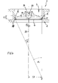
- This "first eccentricity" of the cone surface 18 is in Fig. 4 illustrated with X1.
- the sealing element 14 of the valve disc 6 has a conical surface 24 adapted to the conical surface 18.
- the straight surface zone 22 can also be referred to as a "90 ° side” because the conical surface 18 here forms a right angle with the closing plane of the valve disc 6 and with the opening plane of the passage 4.
- the "90 ° side" with the straight surface zone 22 of the sealing seat 16 is located on a plane perpendicular to the axis of rotation 12 transverse axis of the opening plane, so that the flap disc 6 is pressed when pivoting in the shut-off with the sealing element 14 approximately radially against the surface zone 22.
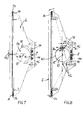
- the axis of rotation 12 of the shaft 10 is offset relative to the longitudinal central axis 26 of the disc 6 by an offset X2, in particular in the direction of the straight surface zone 22 of the sealing seat 16 and the area adapted to the area 22 area the sealing element 14 of the Valve disc 6; see also Fig. 7 ,
- the longitudinal central axis 20 of the passage 4 and the longitudinal central axis 26 of the valve disc 6 preferably coincide.
- Fig. 4 is provided as a "third eccentricity" that the axis of rotation 12 of the shaft 10 is arranged offset relative to the sealing plane defined by the sealing seat 16 in the passage direction, in the direction in which the conical surface 18 of the sealing seat 16 in Diameter expanded. This offset is in Fig. 4 marked with X3.
- the flap disc 6 is connected to the shaft 10 so as to be relatively movable in the shaft transverse direction such that the flap disc 6 moves further against the sealing seat in the shut-off position by a further rotation of the shaft 10 in the closing direction relative to the axially fixed shaft 10 16 is movable.
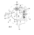
- This is practically an additional movement in a "fourth axis", which in Fig. 4 . 8th and 9 is illustrated with X4.
- the shaft 10 extends through two identical bearing openings 28 of the valve disc 6 spaced apart in the shaft longitudinal direction.
- Each bearing opening 28 is proportionately formed by a bearing shell 30 of the valve disc 6 and by a bearing shell 32 of a separate bearing pressure piece 34.
- Each bearing pressure piece 34 is arranged on the side facing away from the sealing seat 16 side and acted upon by a force acting in the direction of the shaft 10 spring force F.
- the spring force F is dimensioned so that the flap disc 6 is held in its unloaded state in the open position substantially free of play on the shaft 10.
- the shaft 10 has in the region of each bearing opening 28 at a circumferential location on a radially projecting driver element 36 which engages in such a formed within the respective bearing opening 28 between the bearing shells 30, 32 of the valve disc 6 and the bearing pressure piece 34 Mit strictlyausNFung 38 that on the one hand the disc 6 torque-locking connected to the shaft 10, and that on the other hand in the shut-off on the Carrier element 36, the valve disc 6 against the spring force F of the shaft 10 and the bearing pressure piece 34 is moved away.
- the driver element 36 Due to the arrangement of the driver element 36 on only one peripheral side of the shaft 10 is in this movement of the disc 6 to a pivoting movement away from the shaft 10, wherein between the bearing pressure piece 34 opposite side of the shaft 10 and the bearing shell 30 of the disc 6 a Gap 40 is created; see Fig. 8 and 9 , Preferably, the driver element 36 is arranged on that side of the shaft 10, which - with respect to the shut-off position - in the straight surface zone 22 of the sealing seat 16 has diametrically opposite direction. Between the valve disc 6 and the bearing pressure piece 34 on the one hand on the side of the driving element 36 a movement play for the described relative movement and on the other hand on the approximately diametrically opposite side acting as a tilting axis stop 42 is formed. In Fig.
- driver element 36 As a driver element 36, a so-called key or a wedge element may be provided, wherein the driver element 36 sits proportionately in a groove-like recess of the shaft 10 and in the Mit ConverseausEnglishung 38 between the disc 6 and the bearing pressure piece 34.
- the spring pressure F acting on the bearing pressure piece 34 can be generated by a spring element 44, which sits with prestress between the bearing pressure piece 34 and an abutment 46 fixedly connected to the valve disk 6.
- the spring element 44 may be formed as a plate spring package.
- the spring force F can be in the range of 10,000 to 15,000 N, for example, with the valve open by 12,500 N and with the valve closed by 15,000 N.
- Each bearing pressure piece 34 can be inserted from the outer periphery of the disc 6 forth parallel to the disc plane in a receptacle of the disc 6.
- a sliding connection in the manner of a dovetail connection or a T-connection is possible.
- the invention is not limited to the illustrated and described embodiments, but also includes all the same in the context of the invention embodiments. Furthermore, the invention has hitherto not been limited to the combination of features defined in the independent claim, but may also be defined by any other combination of specific features of all individually disclosed individual features. This means that in principle virtually every individual feature of the independent claim can be omitted or replaced by at least one individual feature disclosed elsewhere in the application. In this respect, the claims are to be understood merely as a first formulation attempt for an invention.
Landscapes
- Engineering & Computer Science (AREA)
- General Engineering & Computer Science (AREA)
- Mechanical Engineering (AREA)
- Lift Valve (AREA)
Applications Claiming Priority (1)
| Application Number | Priority Date | Filing Date | Title |
|---|---|---|---|
| US21530009P | 2009-05-04 | 2009-05-04 |
Publications (1)
| Publication Number | Publication Date |
|---|---|
| EP2249067A1 true EP2249067A1 (fr) | 2010-11-10 |
Family
ID=42233929
Family Applications (1)
| Application Number | Title | Priority Date | Filing Date |
|---|---|---|---|
| EP10156990A Withdrawn EP2249067A1 (fr) | 2009-05-04 | 2010-03-19 | Soupape de disque à clapets |
Country Status (2)
| Country | Link |
|---|---|
| US (1) | US20100276621A1 (fr) |
| EP (1) | EP2249067A1 (fr) |
Cited By (1)
| Publication number | Priority date | Publication date | Assignee | Title |
|---|---|---|---|---|
| US11879554B2 (en) | 2021-03-26 | 2024-01-23 | Dezurik, Inc. | High-performance butterfly valve |
Families Citing this family (7)
| Publication number | Priority date | Publication date | Assignee | Title |
|---|---|---|---|---|
| US8763987B2 (en) * | 2009-11-03 | 2014-07-01 | Mks Instruments, Inc. | Butterfly valve and system employing same and method for using same field |
| CN103026109B (zh) * | 2010-05-14 | 2014-09-10 | 布雷国际有限公司 | 阀组件和阀组件的使用方法 |
| US8899257B2 (en) * | 2011-08-09 | 2014-12-02 | Amot Controls Corp. | Disc assembly for a valve and method of making the same |
| JP6158110B2 (ja) * | 2014-02-07 | 2017-07-05 | 株式会社オーケーエム | 三重偏心型バタフライバルブ |
| US10100934B2 (en) | 2015-02-25 | 2018-10-16 | Elkhart Brass Manufacturing Company, Inc. | Valve with movable valve seat |
| JP7248286B2 (ja) * | 2019-02-28 | 2023-03-29 | 株式会社キッツ | 二重偏心形バタフライバルブの弁体と二重偏心形バタフライバルブ |
| JP7248287B2 (ja) * | 2019-02-28 | 2023-03-29 | 株式会社キッツ | 二重偏心形バタフライバルブの弁体と二重偏心形バタフライバルブ |
Citations (3)
| Publication number | Priority date | Publication date | Assignee | Title |
|---|---|---|---|---|
| US3498583A (en) * | 1966-10-07 | 1970-03-03 | Martin Marietta Corp | Compound movement butterfly valve |
| DE3744548A1 (de) | 1987-01-02 | 1988-07-14 | Somas Ventiler | Drosselventil |
| EP0320491A2 (fr) | 1985-05-30 | 1989-06-14 | SCHMIDT, Fritz | Elément de fermeture pour tuyauterie |
Family Cites Families (13)
| Publication number | Priority date | Publication date | Assignee | Title |
|---|---|---|---|---|
| US2673061A (en) * | 1950-08-14 | 1954-03-23 | William S Woods | Valve of the hybrid poppetbutterfly type |
| US2934310A (en) * | 1955-11-02 | 1960-04-26 | Kinney Eng Inc S P | Tight closing butterfly valve |
| US2892609A (en) * | 1956-07-31 | 1959-06-30 | Bibbo Carmen | Compound-movement butterfly valve |
| US3065950A (en) * | 1961-01-17 | 1962-11-27 | Thiokol Chemical Corp | Hermetically sealed butterfly poppet valve |
| US3963211A (en) * | 1974-10-23 | 1976-06-15 | Honeywell Inc. | Rotary valve |
| DE2822982C2 (de) * | 1978-05-26 | 1983-06-16 | Honeywell Gmbh, 6000 Frankfurt | Ventil |
| US4280681A (en) * | 1980-01-09 | 1981-07-28 | Koppers Company, Inc. | Center link disc valve |
| CH664198A5 (de) * | 1983-12-13 | 1988-02-15 | Cetec Ag | Absperrvorrichtung. |
| US4817916A (en) * | 1987-03-09 | 1989-04-04 | Jamesbury Corporation | Butterfly valve |
| US5186433A (en) * | 1992-01-21 | 1993-02-16 | General Resource Corporation | Adjustable eccentric valve |
| US5330157A (en) * | 1993-07-28 | 1994-07-19 | Hull Corporation | Rotary disk valve |
| US6135416A (en) * | 1999-02-18 | 2000-10-24 | Varian, Inc. | Butterfly valve |
| US6595488B2 (en) * | 2001-01-19 | 2003-07-22 | Zwick Gmbh | Butterfly valve |
-
2010
- 2010-03-19 EP EP10156990A patent/EP2249067A1/fr not_active Withdrawn
- 2010-03-22 US US12/661,666 patent/US20100276621A1/en not_active Abandoned
Patent Citations (3)
| Publication number | Priority date | Publication date | Assignee | Title |
|---|---|---|---|---|
| US3498583A (en) * | 1966-10-07 | 1970-03-03 | Martin Marietta Corp | Compound movement butterfly valve |
| EP0320491A2 (fr) | 1985-05-30 | 1989-06-14 | SCHMIDT, Fritz | Elément de fermeture pour tuyauterie |
| DE3744548A1 (de) | 1987-01-02 | 1988-07-14 | Somas Ventiler | Drosselventil |
Cited By (1)
| Publication number | Priority date | Publication date | Assignee | Title |
|---|---|---|---|---|
| US11879554B2 (en) | 2021-03-26 | 2024-01-23 | Dezurik, Inc. | High-performance butterfly valve |
Also Published As
| Publication number | Publication date |
|---|---|
| US20100276621A1 (en) | 2010-11-04 |
Similar Documents
| Publication | Publication Date | Title |
|---|---|---|
| EP2249067A1 (fr) | Soupape de disque à clapets | |
| EP1688654B1 (fr) | Clapet à vide | |
| CH700100A1 (de) | Ventilanordnung. | |
| EP1493951B1 (fr) | Vanne papillon | |
| EP2529136B1 (fr) | Robinet d'arrêt pour le domaine des installations de second oeuvre | |
| DE202013103967U1 (de) | Drehschieberventil | |
| DE6931306U (de) | Drehschuetz- oder drosselklappenventil. | |
| DE4402079B4 (de) | Dreh-Absperrorgan | |
| DE2849281C2 (fr) | ||
| EP2183509B1 (fr) | Dispositif de restriction de la section transversale libre d'une conduite de vapeur ou analogue | |
| DE4426471A1 (de) | Drehabsperrorgan | |
| DE4302666A1 (de) | Schnellschlussklappe | |
| DE19959109B4 (de) | Drehklappenventil | |
| EP3369972B1 (fr) | Soupape à disque | |
| EP1712818B1 (fr) | Vanne à diaphragme | |
| DE2732672B1 (de) | Kugelhahn | |
| DE102020134037A1 (de) | Ventil für Fluidleitung mit verbesserter Dichtwirkung und Druckbehälter mit verbessertem Ventil | |
| DE102020213657A1 (de) | Ventilvorrichtung | |
| DE4303477C2 (de) | Absperrarmatur | |
| EP0335997A1 (fr) | Tête de robinet | |
| DE3702386A1 (de) | Kugelhahn | |
| EP2690333A1 (fr) | Robinet de régulation à boisseau sphérique | |
| DE102009012611B3 (de) | Dichtungen für dreifach oder vierfach asymmetrisch aufgebaute Absperrklappen | |
| EP1058797B1 (fr) | Robinet-vanne | |
| EP3591271A1 (fr) | Partie supérieure de soupape |
Legal Events
| Date | Code | Title | Description |
|---|---|---|---|
| PUAI | Public reference made under article 153(3) epc to a published international application that has entered the european phase |
Free format text: ORIGINAL CODE: 0009012 |
|
| AK | Designated contracting states |
Kind code of ref document: A1 Designated state(s): AT BE BG CH CY CZ DE DK EE ES FI FR GB GR HR HU IE IS IT LI LT LU LV MC MK MT NL NO PL PT RO SE SI SK SM TR |
|
| AX | Request for extension of the european patent |
Extension state: AL BA ME RS |
|
| 17P | Request for examination filed |
Effective date: 20110504 |
|
| 17Q | First examination report despatched |
Effective date: 20110831 |
|
| STAA | Information on the status of an ep patent application or granted ep patent |
Free format text: STATUS: THE APPLICATION IS DEEMED TO BE WITHDRAWN |
|
| 18D | Application deemed to be withdrawn |
Effective date: 20141216 |