EP2249073A1 - Agencement de connecteur à fiches - Google Patents
Agencement de connecteur à fiches Download PDFInfo
- Publication number
- EP2249073A1 EP2249073A1 EP20100160660 EP10160660A EP2249073A1 EP 2249073 A1 EP2249073 A1 EP 2249073A1 EP 20100160660 EP20100160660 EP 20100160660 EP 10160660 A EP10160660 A EP 10160660A EP 2249073 A1 EP2249073 A1 EP 2249073A1
- Authority
- EP
- European Patent Office
- Prior art keywords
- hollow body
- clamp
- assembly
- final
- radial
- Prior art date
- Legal status (The legal status is an assumption and is not a legal conclusion. Google has not performed a legal analysis and makes no representation as to the accuracy of the status listed.)
- Granted
Links
- 238000000034 method Methods 0.000 claims abstract description 5
- 230000002093 peripheral effect Effects 0.000 claims description 8
- 238000007789 sealing Methods 0.000 claims description 6
- 210000002105 tongue Anatomy 0.000 description 29
- 230000000694 effects Effects 0.000 description 2
- 239000007787 solid Substances 0.000 description 2
- 150000001875 compounds Chemical class 0.000 description 1
- 239000012530 fluid Substances 0.000 description 1
- 238000003780 insertion Methods 0.000 description 1
- 230000037431 insertion Effects 0.000 description 1
- 238000007689 inspection Methods 0.000 description 1
- 238000002955 isolation Methods 0.000 description 1
- 230000003584 silencer Effects 0.000 description 1
Images

Classifications
-
- F—MECHANICAL ENGINEERING; LIGHTING; HEATING; WEAPONS; BLASTING
- F16—ENGINEERING ELEMENTS AND UNITS; GENERAL MEASURES FOR PRODUCING AND MAINTAINING EFFECTIVE FUNCTIONING OF MACHINES OR INSTALLATIONS; THERMAL INSULATION IN GENERAL
- F16L—PIPES; JOINTS OR FITTINGS FOR PIPES; SUPPORTS FOR PIPES, CABLES OR PROTECTIVE TUBING; MEANS FOR THERMAL INSULATION IN GENERAL
- F16L55/00—Devices or appurtenances for use in, or in connection with, pipes or pipe systems
- F16L55/10—Means for stopping flow in pipes or hoses
- F16L55/11—Plugs
- F16L55/1141—Plugs the plug being made of elastic material
-
- F—MECHANICAL ENGINEERING; LIGHTING; HEATING; WEAPONS; BLASTING
- F02—COMBUSTION ENGINES; HOT-GAS OR COMBUSTION-PRODUCT ENGINE PLANTS
- F02M—SUPPLYING COMBUSTION ENGINES IN GENERAL WITH COMBUSTIBLE MIXTURES OR CONSTITUENTS THEREOF
- F02M35/00—Combustion-air cleaners, air intakes, intake silencers, or induction systems specially adapted for, or arranged on, internal-combustion engines
- F02M35/10—Air intakes; Induction systems
- F02M35/1015—Air intakes; Induction systems characterised by the engine type
- F02M35/10157—Supercharged engines
-
- F—MECHANICAL ENGINEERING; LIGHTING; HEATING; WEAPONS; BLASTING
- F02—COMBUSTION ENGINES; HOT-GAS OR COMBUSTION-PRODUCT ENGINE PLANTS
- F02M—SUPPLYING COMBUSTION ENGINES IN GENERAL WITH COMBUSTIBLE MIXTURES OR CONSTITUENTS THEREOF
- F02M35/00—Combustion-air cleaners, air intakes, intake silencers, or induction systems specially adapted for, or arranged on, internal-combustion engines
- F02M35/10—Air intakes; Induction systems
- F02M35/10091—Air intakes; Induction systems characterised by details of intake ducts: shapes; connections; arrangements
- F02M35/10144—Connections of intake ducts to each other or to another device
-
- F—MECHANICAL ENGINEERING; LIGHTING; HEATING; WEAPONS; BLASTING
- F02—COMBUSTION ENGINES; HOT-GAS OR COMBUSTION-PRODUCT ENGINE PLANTS
- F02M—SUPPLYING COMBUSTION ENGINES IN GENERAL WITH COMBUSTIBLE MIXTURES OR CONSTITUENTS THEREOF
- F02M35/00—Combustion-air cleaners, air intakes, intake silencers, or induction systems specially adapted for, or arranged on, internal-combustion engines
- F02M35/10—Air intakes; Induction systems
- F02M35/1034—Manufacturing and assembling intake systems
- F02M35/10354—Joining multiple sections together
-
- F—MECHANICAL ENGINEERING; LIGHTING; HEATING; WEAPONS; BLASTING
- F16—ENGINEERING ELEMENTS AND UNITS; GENERAL MEASURES FOR PRODUCING AND MAINTAINING EFFECTIVE FUNCTIONING OF MACHINES OR INSTALLATIONS; THERMAL INSULATION IN GENERAL
- F16L—PIPES; JOINTS OR FITTINGS FOR PIPES; SUPPORTS FOR PIPES, CABLES OR PROTECTIVE TUBING; MEANS FOR THERMAL INSULATION IN GENERAL
- F16L33/00—Arrangements for connecting hoses to rigid members; Rigid hose-connectors, i.e. single members engaging both hoses
- F16L33/02—Hose-clips
- F16L33/025—Hose-clips tightened by deforming radially extending loops or folds
-
- F—MECHANICAL ENGINEERING; LIGHTING; HEATING; WEAPONS; BLASTING
- F16—ENGINEERING ELEMENTS AND UNITS; GENERAL MEASURES FOR PRODUCING AND MAINTAINING EFFECTIVE FUNCTIONING OF MACHINES OR INSTALLATIONS; THERMAL INSULATION IN GENERAL
- F16L—PIPES; JOINTS OR FITTINGS FOR PIPES; SUPPORTS FOR PIPES, CABLES OR PROTECTIVE TUBING; MEANS FOR THERMAL INSULATION IN GENERAL
- F16L37/00—Couplings of the quick-acting type
- F16L37/08—Couplings of the quick-acting type in which the connection between abutting or axially overlapping ends is maintained by locking members
- F16L37/10—Couplings of the quick-acting type in which the connection between abutting or axially overlapping ends is maintained by locking members using a rotary external sleeve or ring on one part
- F16L37/101—Couplings of the quick-acting type in which the connection between abutting or axially overlapping ends is maintained by locking members using a rotary external sleeve or ring on one part in which the coupling is coaxial with the pipe
-
- F—MECHANICAL ENGINEERING; LIGHTING; HEATING; WEAPONS; BLASTING
- F16—ENGINEERING ELEMENTS AND UNITS; GENERAL MEASURES FOR PRODUCING AND MAINTAINING EFFECTIVE FUNCTIONING OF MACHINES OR INSTALLATIONS; THERMAL INSULATION IN GENERAL
- F16L—PIPES; JOINTS OR FITTINGS FOR PIPES; SUPPORTS FOR PIPES, CABLES OR PROTECTIVE TUBING; MEANS FOR THERMAL INSULATION IN GENERAL
- F16L37/00—Couplings of the quick-acting type
- F16L37/08—Couplings of the quick-acting type in which the connection between abutting or axially overlapping ends is maintained by locking members
- F16L37/12—Couplings of the quick-acting type in which the connection between abutting or axially overlapping ends is maintained by locking members using hooks, pawls, or other movable or insertable locking members
- F16L37/1225—Couplings of the quick-acting type in which the connection between abutting or axially overlapping ends is maintained by locking members using hooks, pawls, or other movable or insertable locking members using a retaining member the extremities of which, e.g. in the form of a U, engage behind a shoulder of both parts
-
- F—MECHANICAL ENGINEERING; LIGHTING; HEATING; WEAPONS; BLASTING
- F02—COMBUSTION ENGINES; HOT-GAS OR COMBUSTION-PRODUCT ENGINE PLANTS
- F02B—INTERNAL-COMBUSTION PISTON ENGINES; COMBUSTION ENGINES IN GENERAL
- F02B33/00—Engines characterised by provision of pumps for charging or scavenging
- F02B33/44—Passages conducting the charge from the pump to the engine inlet, e.g. reservoirs
-
- Y—GENERAL TAGGING OF NEW TECHNOLOGICAL DEVELOPMENTS; GENERAL TAGGING OF CROSS-SECTIONAL TECHNOLOGIES SPANNING OVER SEVERAL SECTIONS OF THE IPC; TECHNICAL SUBJECTS COVERED BY FORMER USPC CROSS-REFERENCE ART COLLECTIONS [XRACs] AND DIGESTS
- Y02—TECHNOLOGIES OR APPLICATIONS FOR MITIGATION OR ADAPTATION AGAINST CLIMATE CHANGE
- Y02T—CLIMATE CHANGE MITIGATION TECHNOLOGIES RELATED TO TRANSPORTATION
- Y02T10/00—Road transport of goods or passengers
- Y02T10/10—Internal combustion engine [ICE] based vehicles
- Y02T10/12—Improving ICE efficiencies
-
- Y—GENERAL TAGGING OF NEW TECHNOLOGICAL DEVELOPMENTS; GENERAL TAGGING OF CROSS-SECTIONAL TECHNOLOGIES SPANNING OVER SEVERAL SECTIONS OF THE IPC; TECHNICAL SUBJECTS COVERED BY FORMER USPC CROSS-REFERENCE ART COLLECTIONS [XRACs] AND DIGESTS
- Y10—TECHNICAL SUBJECTS COVERED BY FORMER USPC
- Y10T—TECHNICAL SUBJECTS COVERED BY FORMER US CLASSIFICATION
- Y10T137/00—Fluid handling
- Y10T137/0318—Processes
- Y10T137/0402—Cleaning, repairing, or assembling
- Y10T137/0441—Repairing, securing, replacing, or servicing pipe joint, valve, or tank
Definitions
- the present invention relates to a connector assembly for connecting a first hollow body such as a pipe socket with a second hollow body such as a hose by means of a clamp, wherein the first hollow body has a pre-assembly on which the clamp is preassembled in a pre-assembly, and wherein the first hollow body has a final assembly has, on which the clamp for the connection of the first hollow body with the second hollow body is fixed in a final assembly position.
- Such a connector assembly is from the document DE 196 21 670 A1 known.
- the DE 196 21 670 A1 shows a connector assembly for connecting a hose end with pipe socket, wherein on the pipe socket a clamp is pre-assembled, which is displaced axially when pushing the hose end into a final assembly position. In the final assembly position, the clamp in the axial direction is positively connected to the pipe socket and frictionally connected to the hose end.
- a connector assembly is known in which a spring clamp is widened under tension and is held in this state by means of a clamp. In this pre-assembly position, the spring clip can also be fixed to a retaining ring, which is connected to the pipe socket.
- the document DE 10 2006 047 882 B3 discloses another connector assembly in which a sleeve is clamped to a hose end.
- a connecting ring is locked in a pre-assembly with the sleeve.
- the connecting ring When sliding the hose end onto a socket, the connecting ring also engages in a circumferential groove on the outer circumference of the nozzle.
- an object of the invention is to provide an improved connector assembly, in particular allows a simple and secure final assembly for connection of the two hollow body.
- the present invention is further achieved by a method for connecting a first hollow body such as a pipe socket to a second hollow body such as a hose by means of a clamp, comprising the steps of preassembling the clamp to a pre-assembly portion of the first hollow body, the first and the axially insert the second hollow body into each other, and finally to rotate the clamp relative to the first hollow body, so that the clamp passes into a final assembly position.
- the connector assembly can be realized with few components.
- the final assembly can be done by a simple twisting of the clamp. Furthermore, a safer pre-assembly of the clamp on the first hollow body can be achieved thereby.
- the pre-assembly section has a larger outer diameter than the final assembly section, so that the second hollow body can be pushed axially onto the first hollow body such that at least a portion of the second hollow body is arranged radially inside the clamp.
- the hollow body can be easily inserted into each other, and the clamp can then attack on the outer circumference of the second hollow body to produce the connector.
- pre-assembly section and the final assembly section are connected to each other in the circumferential direction via a peripheral contour.
- the turning process for setting up the final assembly position can be influenced in a targeted manner via the peripheral contour.
- the circumferential contour is further preferably formed continuously, so that no purely radially extending paragraphs or the like are included. This allows for greater control during the twisting process.
- the securing portion has a larger outer diameter than the pre-assembly.
- the securing portion can be realized structurally in a simple manner, in particular as part of the peripheral contour.
- the clamp is also preferably a spring clip, which is tensioned by radial expansion.
- the clamp may initially be radially expanded from its relaxed state to be placed in the preassembly position. In the preassembly position, the spring clip is then held by a radially inwardly acting elastic restoring force.
- the spring clip is in the pre-assembly under tension.
- the clamp has at least one first radial tongue which engages in the preassembly position and / or in the final assembly position in a circumferential groove of the first hollow body.
- the clamp is secured in the pre-assembly and / or in the final assembly position in the axial direction of the first hollow body. If the clamp is a spring clip, the radial tongue is also pressed elastically into the circumferential groove, so that the transport safety can be further increased.
- first radial tongue In general, it is conceivable that only a single first radial tongue is provided, e.g. can extend up to 180 ° over the circumference. However, it is particularly preferred if a plurality of first radial tongues distributed over the circumference are provided on the clamp.
- the clamp has at least one first radial tongue which engages in the preassembly position and / or in the final assembly position in a circumferential groove of the first hollow body, wherein the clamp further comprises at least one second radial tongue which engages in the final assembly position in a radial groove of the second hollow body.
- the connector assembly can have a high connection security.
- the second radial tongue may be formed as a single radial tongue, as described above.
- a plurality of second radial tongues is also provided in this case, which are arranged distributed over the circumference of the clamp.
- the second radial tongue is shorter than the first radial tongue.
- first and / or the second hollow body has a circumferential groove, in which a sealing ring is inserted and which is covered in the final assembly state of the other hollow body to seal the interior of the hollow body relative to the environment.
- the present connector assembly is preferably used for plug-in connection of two hollow body through which preferably a fluid such as charge air is feasible
- the connector according to the invention is equally applicable to compounds of solid bodies.
- the first hollow body and / or the second hollow body may be formed as a solid body, wherein one of the bodies, for example, has an annular flange portion which is pushed onto a corresponding receiving portion of the other body.
- the presently used term of the hollow body is therefore to be understood expanded in this sense.
- the connector assembly according to the invention also allows a safe inspection of the finished connection, depending on the embodiment. In other words, it can be detected from the outside relatively easily whether the clamp is in the correct final assembly position. This is especially true when a first and a second radial tongue in corresponding grooves of the first hollow body or the grab the second hollow body. This is easily recognizable from the outside and can therefore easily be checked.
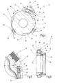
- a connector assembly is generally designated 10.
- the connector assembly 10 includes a pipe socket 12, which may be part of a turbocharger, for example. Furthermore, the connector assembly 10 has a hose 14, which may be, for example, a charge air line. The connector assembly 10 further includes a spring clip 16, by means of which the pipe socket 12 and the hose 14 can be fixed in the nested state.
- the pipe socket 12 in this case has an outer diameter which is adapted to the inner diameter of the hose 14 so that the hose 14 can be slid over the pipe socket 12 in the axial direction.
- the pipe socket 12 has a pre-assembly section 18, on which the spring clip 16 is fixed in a preassembly position, as in Fig. 1 is shown.
- the pre-assembly portion 18 may be formed by a separate, attached to the outer circumference of the pipe socket 12 component, but may also be integrally formed with the pipe socket 12.
- the spring clip 16 has distributed over the circumference of a plurality, in the illustrated embodiment, four holding portions 20, which are offset by 90 ° from each other, as in Fig. 3 is shown. In Fig. 1 two of the holding portions 20 are shown. Each holding section has a first radial tongue 22 which engages in a circumferential groove 24 of the pre-assembly section 18. As a result, the spring clip 16 is axially fixed to the pipe socket 12 in the pre-assembly shown. The spring clip 16 is radially expanded for this purpose to then insert the first radial tabs 22 in the circumferential groove 24, wherein the spring clip 16 is biased in the preassembly.
- the holding portions 20 each further include a second radial tongue 26, which are arranged offset in the axial direction towards the free end of the pipe socket 12.
- the second radial tongues 26 are arranged so that at least a portion of the tube 14, which is pushed onto the pipe socket 12, in the radial Direction within the first Radialzept 22 is located.
- the second radial tongues 26 are preferably shorter than the first radial tongues 22.
- the second radial tongues 26 are in the in Fig. 1 shown pre-assembly positioned so that the tube 14 can be guided past the second radial tongues 26 substantially non-contact.
- a radial groove 28 is formed, in which the second radial tongues 26 engage when the spring clamp 16 is in a final assembly position, as in Fig. 2 is shown.
- the pipe socket 12 and the hose 14 can be positively connected to each other in the axial direction via the spring clip 16.
- Both in the pre-assembly and in the final assembly position acts while a radially inwardly facing spring tension 30, which holds the spring clamp 16 on the one hand in the circumferential groove 24 and the radial groove 28 and on the other hand exerts a radial force on the portion in which the Hose 14, the pipe socket 12 overlaps. Consequently, both an axial positive engagement and a certain sealing effect can be achieved.
- the spring clip 16 may be formed in the circumferential direction 38 substantially continuously from one piece.
- the spring clip 16 in this case has a first clip end and a second clip end, which overlap in the circumferential direction 38, so that an expansion of the spring clip 16 for insertion into the preassembly position by compressing the clip ends is possible.
- FIG. 4 Such an embodiment is in Fig. 4 shown.
- the connector assembly 10 of Fig. 4 corresponds in terms of design and operation generally the connector assembly 10 of Fig. 1 to 3 , The same elements therefore have the same reference numerals. The following section essentially explains the differences.
- the spring clip 16 of Fig. 4 has a first clip end 40 and a second clip end 42 that overlap one another.
- a collet or other gripping device 44 By means of a collet or other gripping device 44, the clamp ends 40, 42 can be grasped and compressed, as indicated by a Aufweitkraft 46.
- the spring clip 16 is widened in the radial direction, so that it can be brought into the pre-assembly position on the pipe socket 12.
- the circumferential groove 24 is in the connector assembly 10 of the Fig. 4 not circumferentially formed in the circumferential direction 38 but divided into a plurality of sections. The number of sections corresponds to the number of holding sections 20; in the presentation of the Fig. 4 There are three holding sections, which are offset by about 120 ° to each other.
- the spring clip 16 is formed from a spring band extending in the circumferential direction 38, wherein a holding portion 20 is formed on the first clip end 40.
- the second clamp end 42 penetrates in the radial direction in Fig. 4 not shown recess of the first clamp end 40, so that the collet 44 can easily attack on the clamp ends 40, 42.
- FIGS. 5 and 6 a further embodiment of a connector assembly 10 is shown, with respect to the structure and operation generally of the connector assembly of Fig. 1 to 3 equivalent.
- the same elements are therefore provided with the same reference numerals. In the following, only the differences will be explained.
- Fig. 5 For one thing is in Fig. 5 to recognize that the pipe socket 12 according to Fig. 5 Part of a pipe 50, which in turn may be part of a turbocharger charge air arrangement.
- the tube 50 when it is connected via the connector assembly 10 with the second hollow body 14, form a silencer.
- the pipe socket 12 on its outer circumference on a circumferential groove 54 into which a sealing ring 52 is inserted as an O-ring.
- the circumferential groove 54 and the inserted therein sealing ring 52 are covered by the tube portion which is pushed onto the pipe socket 12.
- the seal can be achieved by the spring tension 30 acting in the final assembly position (in Fig. 6 not shown).
- the hose 14 is dimensioned so that it axially against a in Fig. 6 unspecified annular shoulder of the pipe socket 12 abuts. In this position, the radial groove 28 is within the second radial tongues 26, so that, starting from the in Fig. 6 shown pre-assembly, the final assembly position can be easily set by turning the spring clip 16.
- the spring clip is pre-mounted on a pipe socket, it is also possible to pre-assemble the spring clip to the hose. In the same way it is possible to connect two pipe sockets or two hoses instead of a hose and a pipe socket with each other, wherein the spring clip can be pre-assembled in each case on one of the two elements.
Landscapes
- Engineering & Computer Science (AREA)
- General Engineering & Computer Science (AREA)
- Mechanical Engineering (AREA)
- Chemical & Material Sciences (AREA)
- Combustion & Propulsion (AREA)
- Manufacturing & Machinery (AREA)
- Quick-Acting Or Multi-Walled Pipe Joints (AREA)
Applications Claiming Priority (1)
| Application Number | Priority Date | Filing Date | Title |
|---|---|---|---|
| DE200910020577 DE102009020577A1 (de) | 2009-05-09 | 2009-05-09 | Steckverbindungsanordnung |
Publications (2)
| Publication Number | Publication Date |
|---|---|
| EP2249073A1 true EP2249073A1 (fr) | 2010-11-10 |
| EP2249073B1 EP2249073B1 (fr) | 2013-06-19 |
Family
ID=42214406
Family Applications (1)
| Application Number | Title | Priority Date | Filing Date |
|---|---|---|---|
| EP20100160660 Not-in-force EP2249073B1 (fr) | 2009-05-09 | 2010-04-22 | Raccord enfiché |
Country Status (5)
| Country | Link |
|---|---|
| US (1) | US8419076B2 (fr) |
| EP (1) | EP2249073B1 (fr) |
| KR (1) | KR20100121576A (fr) |
| DE (1) | DE102009020577A1 (fr) |
| ES (1) | ES2417811T3 (fr) |
Families Citing this family (9)
| Publication number | Priority date | Publication date | Assignee | Title |
|---|---|---|---|---|
| DE102008005619A1 (de) * | 2008-01-23 | 2009-07-30 | GM Global Technology Operations, Inc., Detroit | Schnellverschluss |
| DE102011121828A1 (de) * | 2011-12-21 | 2013-06-27 | Veritas Ag | Steckverbindungsanordnung für Fluidleitungen |
| US9664321B2 (en) * | 2013-05-20 | 2017-05-30 | Steere Enterprises, Inc. | Clean air duct and retaining clip and assembly thereof |
| US10859194B2 (en) | 2013-05-20 | 2020-12-08 | Steere Enterprises, Inc. | Clean air duct and retaining clip and assembly thereof |
| US10359221B2 (en) * | 2014-10-15 | 2019-07-23 | Mpi Corporation | Working fluid output device for temperature control system |
| US9671052B2 (en) * | 2015-10-27 | 2017-06-06 | Whirlpool Corporation | Collet securing device for joining two fluid lines and providing lateral support at the connection of the two fluid lines |
| JP7097110B1 (ja) * | 2021-03-31 | 2022-07-07 | 株式会社トヨックス | 管継手 |
| CN114352447B (zh) * | 2021-12-31 | 2023-04-28 | 安徽美瑞尔滤清器有限公司 | 一种汽车滤清器装配结构 |
| US20250230826A1 (en) * | 2024-01-11 | 2025-07-17 | Tymphany Hk Limited | Quick release structure |
Citations (8)
| Publication number | Priority date | Publication date | Assignee | Title |
|---|---|---|---|---|
| US1477440A (en) * | 1920-09-11 | 1923-12-11 | Jr Frederick A Grier | Coupling device |
| EP0452172A1 (fr) * | 1990-03-29 | 1991-10-16 | Hutchinson S.A. | Dispositif d'assemblage rapide par encliquetage pour échangeurs de chaleur de véhicules automobiles |
| DE19506144C1 (de) | 1995-02-22 | 1996-05-30 | Rasmussen Gmbh | Vorrichtung zum Festklemmen eines auf einem Rohrendabschnitt aufgeschobenen Schlauchendabschnitts |
| DE19621670A1 (de) | 1996-05-30 | 1997-12-04 | Henn Gmbh & Co Kg | Schelle mit axialer Haltevorrichtung |
| EP0924453A1 (fr) * | 1997-12-20 | 1999-06-23 | DaimlerChrysler AG | Raccord de conduit détachable, en particulier pour les conduits de transport d'air |
| DE102006047882B3 (de) | 2006-10-10 | 2007-08-02 | Rasmussen Gmbh | Steckverbindungsanordnung für einen Schlauch und ein Rohr |
| EP1821022A1 (fr) * | 2006-02-21 | 2007-08-22 | Societe Des Polymeres Barre Thomas | Raccord rapide à encliquetage |
| DE102007045023A1 (de) * | 2007-09-19 | 2009-04-02 | Norma Germany Gmbh | Steckverbindungsanordnung für Fluidleitungen |
Family Cites Families (9)
| Publication number | Priority date | Publication date | Assignee | Title |
|---|---|---|---|---|
| US373292A (en) * | 1887-11-15 | Coupling for hose | ||
| US747412A (en) * | 1903-10-24 | 1903-12-22 | August Henry Getz | Hose-coupling. |
| US1069904A (en) * | 1913-02-06 | 1913-08-12 | William E Sanders | Fire-hose connection. |
| US1369304A (en) * | 1919-10-13 | 1921-02-22 | Schram Carl | Coupling |
| US1544004A (en) * | 1924-07-10 | 1925-06-30 | Henderson Albert | Pipe coupling |
| US2004967A (en) * | 1934-07-24 | 1935-06-18 | Ideal Hose Coupling Company | Hose coupling |
| DK0401083T3 (da) * | 1989-05-29 | 1994-04-25 | Autobrevets | Indretning for tilvejebringelse af en tæt samling mellem et rør og en slange |
| FR2863683B1 (fr) * | 2003-12-10 | 2006-02-17 | Legris Sa | Dispositif de raccordement instantane |
| DE102008005619A1 (de) * | 2008-01-23 | 2009-07-30 | GM Global Technology Operations, Inc., Detroit | Schnellverschluss |
-
2009
- 2009-05-09 DE DE200910020577 patent/DE102009020577A1/de not_active Withdrawn
-
2010
- 2010-04-22 EP EP20100160660 patent/EP2249073B1/fr not_active Not-in-force
- 2010-04-22 ES ES10160660T patent/ES2417811T3/es active Active
- 2010-04-29 US US12/769,684 patent/US8419076B2/en not_active Expired - Fee Related
- 2010-05-07 KR KR1020100042872A patent/KR20100121576A/ko not_active Withdrawn
Patent Citations (8)
| Publication number | Priority date | Publication date | Assignee | Title |
|---|---|---|---|---|
| US1477440A (en) * | 1920-09-11 | 1923-12-11 | Jr Frederick A Grier | Coupling device |
| EP0452172A1 (fr) * | 1990-03-29 | 1991-10-16 | Hutchinson S.A. | Dispositif d'assemblage rapide par encliquetage pour échangeurs de chaleur de véhicules automobiles |
| DE19506144C1 (de) | 1995-02-22 | 1996-05-30 | Rasmussen Gmbh | Vorrichtung zum Festklemmen eines auf einem Rohrendabschnitt aufgeschobenen Schlauchendabschnitts |
| DE19621670A1 (de) | 1996-05-30 | 1997-12-04 | Henn Gmbh & Co Kg | Schelle mit axialer Haltevorrichtung |
| EP0924453A1 (fr) * | 1997-12-20 | 1999-06-23 | DaimlerChrysler AG | Raccord de conduit détachable, en particulier pour les conduits de transport d'air |
| EP1821022A1 (fr) * | 2006-02-21 | 2007-08-22 | Societe Des Polymeres Barre Thomas | Raccord rapide à encliquetage |
| DE102006047882B3 (de) | 2006-10-10 | 2007-08-02 | Rasmussen Gmbh | Steckverbindungsanordnung für einen Schlauch und ein Rohr |
| DE102007045023A1 (de) * | 2007-09-19 | 2009-04-02 | Norma Germany Gmbh | Steckverbindungsanordnung für Fluidleitungen |
Also Published As
| Publication number | Publication date |
|---|---|
| KR20100121576A (ko) | 2010-11-18 |
| ES2417811T3 (es) | 2013-08-09 |
| EP2249073B1 (fr) | 2013-06-19 |
| US8419076B2 (en) | 2013-04-16 |
| US20100282329A1 (en) | 2010-11-11 |
| DE102009020577A1 (de) | 2010-11-11 |
Similar Documents
| Publication | Publication Date | Title |
|---|---|---|
| EP2249073B1 (fr) | Raccord enfiché | |
| DE69209919T2 (de) | Anzeigevorrichtung für eine Schnellverschlusskupplung | |
| DE102007008066B4 (de) | Fitting | |
| EP1805447B1 (fr) | Raccord enfichable resistant a la traction | |
| DE69201673T2 (de) | Verbindungselement zur Schnellkupplung eines Rohres. | |
| DE2652207A1 (de) | Rohrschnellkupplung | |
| DE2534956A1 (de) | Rohrkupplung | |
| EP2880349A1 (fr) | Dispositif de raccordement rapide pour le raccordement libérable d'une conduite de fluide à une rallonge | |
| DE69622346T2 (de) | Verbindungs- und Verstellvorrichtung für zwei Teile eines Bowdenzuges und Verfahren zum Zusammenbau | |
| EP3526507B1 (fr) | Connecteur, module de connecteur et procédé permettant de produire un connecteur | |
| DE102012106232B3 (de) | Rohrverbinder, Abgasrohrsystem sowie Montageverfahren | |
| DE29900796U1 (de) | Vorrichtung zum Verbinden eines Rohrstutzens, rohrförmigen Armaturenteils oder Fittings mit einem Rohr | |
| EP0615089A1 (fr) | Connexion enfichable et détachable pour conduits à haute pression | |
| DE69507100T2 (de) | Verschlussstopfen für eine Schnellverbindung | |
| DE10347927B4 (de) | Verfahren und Vorrichtung zur Herstellung einer Rohrpressverbindung an einer Steckverbindung | |
| DE112014003608B4 (de) | Schnellverbinder | |
| AT523394B1 (de) | Kopplungsverfahren von Steckverbindern zu einer Steckerbaugruppe und Steckerbaugruppe | |
| DE69401385T2 (de) | Schnellkupplung | |
| DE3741250A1 (de) | Vorrichtung zum gegenseitigen verbinden von zwei leitungen, insbesondere kraftstoffleitungen | |
| DE3705610A1 (de) | Loesbare steckverbindung fuer rohrleitungen | |
| CH581273A5 (en) | Snap connection between hose ends - has inner and outer sleeves with O-ring seal and finger with ridge and groove | |
| EP2568207B1 (fr) | Raccordement de tuyau | |
| DE102020100096A1 (de) | Fitting | |
| WO2018210622A1 (fr) | Dispositif de raccordement | |
| DE102007056882A1 (de) | Sicherungselement |
Legal Events
| Date | Code | Title | Description |
|---|---|---|---|
| PUAI | Public reference made under article 153(3) epc to a published international application that has entered the european phase |
Free format text: ORIGINAL CODE: 0009012 |
|
| AK | Designated contracting states |
Kind code of ref document: A1 Designated state(s): AT BE BG CH CY CZ DE DK EE ES FI FR GB GR HR HU IE IS IT LI LT LU LV MC MK MT NL NO PL PT RO SE SI SK SM TR |
|
| AX | Request for extension of the european patent |
Extension state: AL BA ME RS |
|
| 17P | Request for examination filed |
Effective date: 20110509 |
|
| 17Q | First examination report despatched |
Effective date: 20120621 |
|
| GRAP | Despatch of communication of intention to grant a patent |
Free format text: ORIGINAL CODE: EPIDOSNIGR1 |
|
| RIC1 | Information provided on ipc code assigned before grant |
Ipc: F16L 37/10 20060101AFI20121121BHEP Ipc: F16L 37/12 20060101ALI20121121BHEP Ipc: F16L 21/08 20060101ALI20121121BHEP |
|
| GRAS | Grant fee paid |
Free format text: ORIGINAL CODE: EPIDOSNIGR3 |
|
| GRAA | (expected) grant |
Free format text: ORIGINAL CODE: 0009210 |
|
| AK | Designated contracting states |
Kind code of ref document: B1 Designated state(s): AT BE BG CH CY CZ DE DK EE ES FI FR GB GR HR HU IE IS IT LI LT LU LV MC MK MT NL NO PL PT RO SE SI SK SM TR |
|
| REG | Reference to a national code |
Ref country code: GB Ref legal event code: FG4D Free format text: NOT ENGLISH |
|
| REG | Reference to a national code |
Ref country code: CH Ref legal event code: EP |
|
| REG | Reference to a national code |
Ref country code: AT Ref legal event code: REF Ref document number: 617864 Country of ref document: AT Kind code of ref document: T Effective date: 20130715 |
|
| REG | Reference to a national code |
Ref country code: IE Ref legal event code: FG4D Free format text: LANGUAGE OF EP DOCUMENT: GERMAN |
|
| REG | Reference to a national code |
Ref country code: ES Ref legal event code: FG2A Ref document number: 2417811 Country of ref document: ES Kind code of ref document: T3 Effective date: 20130809 |
|
| REG | Reference to a national code |
Ref country code: DE Ref legal event code: R096 Ref document number: 502010003694 Country of ref document: DE Effective date: 20130814 |
|
| PG25 | Lapsed in a contracting state [announced via postgrant information from national office to epo] |
Ref country code: SE Free format text: LAPSE BECAUSE OF FAILURE TO SUBMIT A TRANSLATION OF THE DESCRIPTION OR TO PAY THE FEE WITHIN THE PRESCRIBED TIME-LIMIT Effective date: 20130619 Ref country code: LT Free format text: LAPSE BECAUSE OF FAILURE TO SUBMIT A TRANSLATION OF THE DESCRIPTION OR TO PAY THE FEE WITHIN THE PRESCRIBED TIME-LIMIT Effective date: 20130619 Ref country code: FI Free format text: LAPSE BECAUSE OF FAILURE TO SUBMIT A TRANSLATION OF THE DESCRIPTION OR TO PAY THE FEE WITHIN THE PRESCRIBED TIME-LIMIT Effective date: 20130619 Ref country code: SI Free format text: LAPSE BECAUSE OF FAILURE TO SUBMIT A TRANSLATION OF THE DESCRIPTION OR TO PAY THE FEE WITHIN THE PRESCRIBED TIME-LIMIT Effective date: 20130619 Ref country code: NO Free format text: LAPSE BECAUSE OF FAILURE TO SUBMIT A TRANSLATION OF THE DESCRIPTION OR TO PAY THE FEE WITHIN THE PRESCRIBED TIME-LIMIT Effective date: 20130919 Ref country code: GR Free format text: LAPSE BECAUSE OF FAILURE TO SUBMIT A TRANSLATION OF THE DESCRIPTION OR TO PAY THE FEE WITHIN THE PRESCRIBED TIME-LIMIT Effective date: 20130920 |
|
| REG | Reference to a national code |
Ref country code: LT Ref legal event code: MG4D |
|
| PG25 | Lapsed in a contracting state [announced via postgrant information from national office to epo] |
Ref country code: BG Free format text: LAPSE BECAUSE OF FAILURE TO SUBMIT A TRANSLATION OF THE DESCRIPTION OR TO PAY THE FEE WITHIN THE PRESCRIBED TIME-LIMIT Effective date: 20130919 Ref country code: HR Free format text: LAPSE BECAUSE OF FAILURE TO SUBMIT A TRANSLATION OF THE DESCRIPTION OR TO PAY THE FEE WITHIN THE PRESCRIBED TIME-LIMIT Effective date: 20130619 |
|
| REG | Reference to a national code |
Ref country code: NL Ref legal event code: VDEP Effective date: 20130619 |
|
| PG25 | Lapsed in a contracting state [announced via postgrant information from national office to epo] |
Ref country code: LV Free format text: LAPSE BECAUSE OF FAILURE TO SUBMIT A TRANSLATION OF THE DESCRIPTION OR TO PAY THE FEE WITHIN THE PRESCRIBED TIME-LIMIT Effective date: 20130619 |
|
| PG25 | Lapsed in a contracting state [announced via postgrant information from national office to epo] |
Ref country code: SK Free format text: LAPSE BECAUSE OF FAILURE TO SUBMIT A TRANSLATION OF THE DESCRIPTION OR TO PAY THE FEE WITHIN THE PRESCRIBED TIME-LIMIT Effective date: 20130619 Ref country code: CY Free format text: LAPSE BECAUSE OF FAILURE TO SUBMIT A TRANSLATION OF THE DESCRIPTION OR TO PAY THE FEE WITHIN THE PRESCRIBED TIME-LIMIT Effective date: 20130911 Ref country code: PT Free format text: LAPSE BECAUSE OF FAILURE TO SUBMIT A TRANSLATION OF THE DESCRIPTION OR TO PAY THE FEE WITHIN THE PRESCRIBED TIME-LIMIT Effective date: 20131021 Ref country code: EE Free format text: LAPSE BECAUSE OF FAILURE TO SUBMIT A TRANSLATION OF THE DESCRIPTION OR TO PAY THE FEE WITHIN THE PRESCRIBED TIME-LIMIT Effective date: 20130619 Ref country code: IS Free format text: LAPSE BECAUSE OF FAILURE TO SUBMIT A TRANSLATION OF THE DESCRIPTION OR TO PAY THE FEE WITHIN THE PRESCRIBED TIME-LIMIT Effective date: 20131019 Ref country code: CZ Free format text: LAPSE BECAUSE OF FAILURE TO SUBMIT A TRANSLATION OF THE DESCRIPTION OR TO PAY THE FEE WITHIN THE PRESCRIBED TIME-LIMIT Effective date: 20130619 |
|
| PG25 | Lapsed in a contracting state [announced via postgrant information from national office to epo] |
Ref country code: NL Free format text: LAPSE BECAUSE OF FAILURE TO SUBMIT A TRANSLATION OF THE DESCRIPTION OR TO PAY THE FEE WITHIN THE PRESCRIBED TIME-LIMIT Effective date: 20130619 Ref country code: PL Free format text: LAPSE BECAUSE OF FAILURE TO SUBMIT A TRANSLATION OF THE DESCRIPTION OR TO PAY THE FEE WITHIN THE PRESCRIBED TIME-LIMIT Effective date: 20130619 Ref country code: RO Free format text: LAPSE BECAUSE OF FAILURE TO SUBMIT A TRANSLATION OF THE DESCRIPTION OR TO PAY THE FEE WITHIN THE PRESCRIBED TIME-LIMIT Effective date: 20130619 |
|
| PG25 | Lapsed in a contracting state [announced via postgrant information from national office to epo] |
Ref country code: CY Free format text: LAPSE BECAUSE OF FAILURE TO SUBMIT A TRANSLATION OF THE DESCRIPTION OR TO PAY THE FEE WITHIN THE PRESCRIBED TIME-LIMIT Effective date: 20130619 |
|
| PLBE | No opposition filed within time limit |
Free format text: ORIGINAL CODE: 0009261 |
|
| STAA | Information on the status of an ep patent application or granted ep patent |
Free format text: STATUS: NO OPPOSITION FILED WITHIN TIME LIMIT |
|
| PG25 | Lapsed in a contracting state [announced via postgrant information from national office to epo] |
Ref country code: DK Free format text: LAPSE BECAUSE OF FAILURE TO SUBMIT A TRANSLATION OF THE DESCRIPTION OR TO PAY THE FEE WITHIN THE PRESCRIBED TIME-LIMIT Effective date: 20130619 |
|
| 26N | No opposition filed |
Effective date: 20140320 |
|
| REG | Reference to a national code |
Ref country code: DE Ref legal event code: R097 Ref document number: 502010003694 Country of ref document: DE Effective date: 20140320 |
|
| PG25 | Lapsed in a contracting state [announced via postgrant information from national office to epo] |
Ref country code: MC Free format text: LAPSE BECAUSE OF FAILURE TO SUBMIT A TRANSLATION OF THE DESCRIPTION OR TO PAY THE FEE WITHIN THE PRESCRIBED TIME-LIMIT Effective date: 20130619 Ref country code: LU Free format text: LAPSE BECAUSE OF FAILURE TO SUBMIT A TRANSLATION OF THE DESCRIPTION OR TO PAY THE FEE WITHIN THE PRESCRIBED TIME-LIMIT Effective date: 20140422 |
|
| REG | Reference to a national code |
Ref country code: CH Ref legal event code: PL |
|
| REG | Reference to a national code |
Ref country code: IE Ref legal event code: MM4A |
|
| PG25 | Lapsed in a contracting state [announced via postgrant information from national office to epo] |
Ref country code: LI Free format text: LAPSE BECAUSE OF NON-PAYMENT OF DUE FEES Effective date: 20140430 Ref country code: CH Free format text: LAPSE BECAUSE OF NON-PAYMENT OF DUE FEES Effective date: 20140430 |
|
| REG | Reference to a national code |
Ref country code: FR Ref legal event code: PLFP Year of fee payment: 6 |
|
| PG25 | Lapsed in a contracting state [announced via postgrant information from national office to epo] |
Ref country code: IE Free format text: LAPSE BECAUSE OF NON-PAYMENT OF DUE FEES Effective date: 20140422 |
|
| PGFP | Annual fee paid to national office [announced via postgrant information from national office to epo] |
Ref country code: GB Payment date: 20150420 Year of fee payment: 6 Ref country code: ES Payment date: 20150427 Year of fee payment: 6 |
|
| PGFP | Annual fee paid to national office [announced via postgrant information from national office to epo] |
Ref country code: FR Payment date: 20150421 Year of fee payment: 6 Ref country code: IT Payment date: 20150422 Year of fee payment: 6 |
|
| PG25 | Lapsed in a contracting state [announced via postgrant information from national office to epo] |
Ref country code: MT Free format text: LAPSE BECAUSE OF FAILURE TO SUBMIT A TRANSLATION OF THE DESCRIPTION OR TO PAY THE FEE WITHIN THE PRESCRIBED TIME-LIMIT Effective date: 20130619 |
|
| PG25 | Lapsed in a contracting state [announced via postgrant information from national office to epo] |
Ref country code: SM Free format text: LAPSE BECAUSE OF FAILURE TO SUBMIT A TRANSLATION OF THE DESCRIPTION OR TO PAY THE FEE WITHIN THE PRESCRIBED TIME-LIMIT Effective date: 20130619 |
|
| REG | Reference to a national code |
Ref country code: AT Ref legal event code: MM01 Ref document number: 617864 Country of ref document: AT Kind code of ref document: T Effective date: 20150422 |
|
| PG25 | Lapsed in a contracting state [announced via postgrant information from national office to epo] |
Ref country code: TR Free format text: LAPSE BECAUSE OF FAILURE TO SUBMIT A TRANSLATION OF THE DESCRIPTION OR TO PAY THE FEE WITHIN THE PRESCRIBED TIME-LIMIT Effective date: 20130619 Ref country code: BE Free format text: LAPSE BECAUSE OF FAILURE TO SUBMIT A TRANSLATION OF THE DESCRIPTION OR TO PAY THE FEE WITHIN THE PRESCRIBED TIME-LIMIT Effective date: 20140430 Ref country code: HU Free format text: LAPSE BECAUSE OF FAILURE TO SUBMIT A TRANSLATION OF THE DESCRIPTION OR TO PAY THE FEE WITHIN THE PRESCRIBED TIME-LIMIT; INVALID AB INITIO Effective date: 20100422 |
|
| PG25 | Lapsed in a contracting state [announced via postgrant information from national office to epo] |
Ref country code: AT Free format text: LAPSE BECAUSE OF NON-PAYMENT OF DUE FEES Effective date: 20150422 |
|
| GBPC | Gb: european patent ceased through non-payment of renewal fee |
Effective date: 20160422 |
|
| REG | Reference to a national code |
Ref country code: FR Ref legal event code: ST Effective date: 20161230 |
|
| PG25 | Lapsed in a contracting state [announced via postgrant information from national office to epo] |
Ref country code: FR Free format text: LAPSE BECAUSE OF NON-PAYMENT OF DUE FEES Effective date: 20160502 Ref country code: GB Free format text: LAPSE BECAUSE OF NON-PAYMENT OF DUE FEES Effective date: 20160422 |
|
| PG25 | Lapsed in a contracting state [announced via postgrant information from national office to epo] |
Ref country code: IT Free format text: LAPSE BECAUSE OF NON-PAYMENT OF DUE FEES Effective date: 20160422 |
|
| PGFP | Annual fee paid to national office [announced via postgrant information from national office to epo] |
Ref country code: DE Payment date: 20170601 Year of fee payment: 8 |
|
| REG | Reference to a national code |
Ref country code: DE Ref legal event code: R082 Ref document number: 502010003694 Country of ref document: DE Representative=s name: PATENTSHIP PATENTANWALTSGESELLSCHAFT MBH, DE |
|
| PG25 | Lapsed in a contracting state [announced via postgrant information from national office to epo] |
Ref country code: ES Free format text: LAPSE BECAUSE OF NON-PAYMENT OF DUE FEES Effective date: 20160423 |
|
| PG25 | Lapsed in a contracting state [announced via postgrant information from national office to epo] |
Ref country code: MK Free format text: LAPSE BECAUSE OF FAILURE TO SUBMIT A TRANSLATION OF THE DESCRIPTION OR TO PAY THE FEE WITHIN THE PRESCRIBED TIME-LIMIT Effective date: 20130619 |
|
| REG | Reference to a national code |
Ref country code: DE Ref legal event code: R119 Ref document number: 502010003694 Country of ref document: DE |
|
| REG | Reference to a national code |
Ref country code: ES Ref legal event code: FD2A Effective date: 20181122 |
|
| PG25 | Lapsed in a contracting state [announced via postgrant information from national office to epo] |
Ref country code: DE Free format text: LAPSE BECAUSE OF NON-PAYMENT OF DUE FEES Effective date: 20181101 |