EP2249078A1 - Lampe DEL améliorée à dissipation de chaleur - Google Patents
Lampe DEL améliorée à dissipation de chaleur Download PDFInfo
- Publication number
- EP2249078A1 EP2249078A1 EP10159411A EP10159411A EP2249078A1 EP 2249078 A1 EP2249078 A1 EP 2249078A1 EP 10159411 A EP10159411 A EP 10159411A EP 10159411 A EP10159411 A EP 10159411A EP 2249078 A1 EP2249078 A1 EP 2249078A1
- Authority
- EP
- European Patent Office
- Prior art keywords
- led
- led lamp
- thermally conductive
- lamp
- circuit board
- Prior art date
- Legal status (The legal status is an assumption and is not a legal conclusion. Google has not performed a legal analysis and makes no representation as to the accuracy of the status listed.)
- Granted
Links
Images


Classifications
-
- F—MECHANICAL ENGINEERING; LIGHTING; HEATING; WEAPONS; BLASTING
- F21—LIGHTING
- F21V—FUNCTIONAL FEATURES OR DETAILS OF LIGHTING DEVICES OR SYSTEMS THEREOF; STRUCTURAL COMBINATIONS OF LIGHTING DEVICES WITH OTHER ARTICLES, NOT OTHERWISE PROVIDED FOR
- F21V29/00—Protecting lighting devices from thermal damage; Cooling or heating arrangements specially adapted for lighting devices or systems
- F21V29/50—Cooling arrangements
- F21V29/70—Cooling arrangements characterised by passive heat-dissipating elements, e.g. heat-sinks
-
- F—MECHANICAL ENGINEERING; LIGHTING; HEATING; WEAPONS; BLASTING
- F21—LIGHTING
- F21K—NON-ELECTRIC LIGHT SOURCES USING LUMINESCENCE; LIGHT SOURCES USING ELECTROCHEMILUMINESCENCE; LIGHT SOURCES USING CHARGES OF COMBUSTIBLE MATERIAL; LIGHT SOURCES USING SEMICONDUCTOR DEVICES AS LIGHT-GENERATING ELEMENTS; LIGHT SOURCES NOT OTHERWISE PROVIDED FOR
- F21K9/00—Light sources using semiconductor devices as light-generating elements, e.g. using light-emitting diodes [LED] or lasers
- F21K9/20—Light sources comprising attachment means
- F21K9/23—Retrofit light sources for lighting devices with a single fitting for each light source, e.g. for substitution of incandescent lamps with bayonet or threaded fittings
- F21K9/232—Retrofit light sources for lighting devices with a single fitting for each light source, e.g. for substitution of incandescent lamps with bayonet or threaded fittings specially adapted for generating an essentially omnidirectional light distribution, e.g. with a glass bulb
-
- F—MECHANICAL ENGINEERING; LIGHTING; HEATING; WEAPONS; BLASTING
- F21—LIGHTING
- F21V—FUNCTIONAL FEATURES OR DETAILS OF LIGHTING DEVICES OR SYSTEMS THEREOF; STRUCTURAL COMBINATIONS OF LIGHTING DEVICES WITH OTHER ARTICLES, NOT OTHERWISE PROVIDED FOR
- F21V29/00—Protecting lighting devices from thermal damage; Cooling or heating arrangements specially adapted for lighting devices or systems
- F21V29/50—Cooling arrangements
- F21V29/70—Cooling arrangements characterised by passive heat-dissipating elements, e.g. heat-sinks
- F21V29/80—Cooling arrangements characterised by passive heat-dissipating elements, e.g. heat-sinks with pins or wires
-
- F—MECHANICAL ENGINEERING; LIGHTING; HEATING; WEAPONS; BLASTING
- F21—LIGHTING
- F21V—FUNCTIONAL FEATURES OR DETAILS OF LIGHTING DEVICES OR SYSTEMS THEREOF; STRUCTURAL COMBINATIONS OF LIGHTING DEVICES WITH OTHER ARTICLES, NOT OTHERWISE PROVIDED FOR
- F21V29/00—Protecting lighting devices from thermal damage; Cooling or heating arrangements specially adapted for lighting devices or systems
- F21V29/85—Protecting lighting devices from thermal damage; Cooling or heating arrangements specially adapted for lighting devices or systems characterised by the material
-
- F—MECHANICAL ENGINEERING; LIGHTING; HEATING; WEAPONS; BLASTING
- F21—LIGHTING
- F21V—FUNCTIONAL FEATURES OR DETAILS OF LIGHTING DEVICES OR SYSTEMS THEREOF; STRUCTURAL COMBINATIONS OF LIGHTING DEVICES WITH OTHER ARTICLES, NOT OTHERWISE PROVIDED FOR
- F21V3/00—Globes; Bowls; Cover glasses
- F21V3/02—Globes; Bowls; Cover glasses characterised by the shape
-
- F—MECHANICAL ENGINEERING; LIGHTING; HEATING; WEAPONS; BLASTING
- F21—LIGHTING
- F21V—FUNCTIONAL FEATURES OR DETAILS OF LIGHTING DEVICES OR SYSTEMS THEREOF; STRUCTURAL COMBINATIONS OF LIGHTING DEVICES WITH OTHER ARTICLES, NOT OTHERWISE PROVIDED FOR
- F21V3/00—Globes; Bowls; Cover glasses
- F21V3/04—Globes; Bowls; Cover glasses characterised by materials, surface treatments or coatings
- F21V3/049—Patterns or structured surfaces for diffusing light, e.g. frosted surfaces
-
- F—MECHANICAL ENGINEERING; LIGHTING; HEATING; WEAPONS; BLASTING
- F21—LIGHTING
- F21V—FUNCTIONAL FEATURES OR DETAILS OF LIGHTING DEVICES OR SYSTEMS THEREOF; STRUCTURAL COMBINATIONS OF LIGHTING DEVICES WITH OTHER ARTICLES, NOT OTHERWISE PROVIDED FOR
- F21V3/00—Globes; Bowls; Cover glasses
- F21V3/04—Globes; Bowls; Cover glasses characterised by materials, surface treatments or coatings
- F21V3/10—Globes; Bowls; Cover glasses characterised by materials, surface treatments or coatings characterised by coatings
-
- F—MECHANICAL ENGINEERING; LIGHTING; HEATING; WEAPONS; BLASTING
- F21—LIGHTING
- F21Y—INDEXING SCHEME ASSOCIATED WITH SUBCLASSES F21K, F21L, F21S and F21V, RELATING TO THE FORM OR THE KIND OF THE LIGHT SOURCES OR OF THE COLOUR OF THE LIGHT EMITTED
- F21Y2115/00—Light-generating elements of semiconductor light sources
- F21Y2115/10—Light-emitting diodes [LED]
Definitions
- the present invention is related generally to electric lamps and, more particularly, to a LED lamp which could directly replace an ordinary tungsten, halogen, or electricity-saving light bulb.
- a light emitting diode (LED) lamp using a direct current (DC) LED device as the filament must be equipped with a power converter for converting the alternating current (AC) power voltage into a DC input voltage for the DC LED device.
- the power converter not only requires additional component cost for the LED lamp, but also cannot fit entirely into the standard lamp bases of ordinary light bulbs.
- For a LED lamp to be equipped with a power converter it is necessary to develop special molds to produce containers and corresponding mechanism different from those of ordinary light bulbs to fit the power converter therewithin, which nevertheless increases the cost and volume of the LED lamp.
- a DC LED device generates heat when it is powered on and therefore, an additional heat dissipation mechanism is required to handle the heat.
- the resulting high temperature will reduce the emissive efficiency and service life of the DC LED device and produce other adverse effects such as wavelength shift.
- the power converter particularly the inductor and integrated circuit therein, also generates heat during power conversion, and the consequent high temperature may damage the inductor and integrated circuit and cause failure of the LED lamp accordingly.
- the problems caused by insufficient heat dissipation are aggravated especially in high power applications, such as in lighting fixtures for illumination purposes, where the DC LED device generates relatively more heat.
- some LED lamps use a plurality of low power lamp type LED devices in conjunction with a simple bridge rectifier circuit.
- low power LED devices are poorly accepted in the market due to their generally low brightness, and these LED lamps tend to have serious light attenuation problems as a result of poor heat dissipation.
- An AC LED device includes a plurality of serially and/or parallel connected LED electronic elements manufactured on an epitaxial chip.
- the epitaxial chip is packaged and then connected in series with a resistor having a particular resistance so as to withstand high voltage, e.g., 110 V or 220 V, mains electricity, thus dispensing with the power converter or rectifier circuit required for a DC LED device.
- high voltage e.g. 110 V or 220 V
- An object of the present invention is to provide a LED lamp which enhances the heat dissipation of the AC LED device in the LED lamp.
- Another object of the present invention is to provide a LED lamp which could directly replace an ordinary tungsten, halogen, or electricity-saving light bulb.
- a LED lamp according to the present invention comprises a filament, a lamp base and a thermally conductive electric insulator.
- the filament includes at least one AC LED device, and the thermally conductive electric insulator is filled in a cavity of the lamp base to mechanically contact with the filament and an electrode of the lamp base.
- the thermally conductive electric insulator provides a thermal channel to transfer heat from the filament to the electrode for heat dissipation enhancement.
- Standard lamp bases for ordinary light bulbs can be selected for the lamp base of a LED lamp according to the present invention, and thus the LED lamp could be inserted into the ordinary bulb sockets that generally used in lighting fixtures, without having to modify the system of the lighting fixtures or use an additional adapter.
- Fig. 1 provides a first embodiment according to the present invention, in which a standard lamp base 10 for use with a small light bulb is used to accentuate the features of the present invention.
- the lamp base 10 has two electrodes 12 and 14 for receiving an AC power source.
- the electrode 12 is a metal housing having a spiral-threaded configuration 16 and a cavity 18 therein.
- an AC LED device 20 is used as the filament of the LED lamp, which includes an AC LED epitaxial chip 22 bounded on a leadframe 24 and covered with an encapsulant 26.
- the LED packaging is a well-known technique, the package structure of the AC LED device 20 is not detailed in the drawing for the sake of simplicity.
- a resistor 30 has one end soldered to the electrode 14 and an opposite end connected to a wire 32 that is soldered to the AC LED device 20.
- Another wire 34 has its two ends soldered to the electrode 12 and the AC LED device 20, respectively.
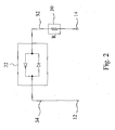
- This LED lamp has the equivalent circuit shown in Fig. 2 , in which the AC LED epitaxial chip 22 and the resistor 30 are connected in series between the electrodes 12 and 14.
- a so-called AC LED epitaxial chip includes LED electronic elements oriented in two opposite directions and connected in parallel between two pins, with at least one LED electronic element in each direction. The LED electronic elements oriented in the two opposite directions are lit during the positive and negative half cycles of the AC power source, respectively.
- the resistor 30 has a resistance R chosen according to the current intensity required by design.
- the resistor 30 also serves to protect the AC LED epitaxial chip 22. More specifically, when a surge occurs in the AC power source connected to the electrodes 12 and 14, the resistor 30 will absorb most of the surge voltage.
- a major feature of the present invention is to fill the cavity 18 with a thermally conductive electric insulator 36 such that the thermally conductive electric insulator 36 is in mechanical contact with the electrode 12 and the filament, i.e. the leadframe 24 in this case, to provide a thermal channel to transfer the heat generated by the AC LED epitaxial chip 22 to the electrode 12 when the AC LED epitaxial chip 22 is powered on to emit light, thereby enhancing the heat dissipation therefrom.
- the leadframe 24 typically includes a metal plate for facilitating heat dissipation from the AC LED epitaxial chip 22.
- the thermally conductive electric insulator 36 also assists in heat dissipation from the resistor 30 because the resistor 30 is buried therein.
- thermally conductive electric insulator 36 it may select epoxy resin, or thermal conductor powder such as aluminum oxide, aluminum nitride, boron nitride, or any other thermally conductive materials in powder form, or a mixture thereof.
- Table 1 shows experiment results of using three different thermally conductive materials in the LED lamp of Fig. 1 .
- Table 1 Thermally conductive electric insulator 36 Voltage of AC power source Power consumed AC LED device 20 Output by brightness (lm) Condition after being lit continuously for 1000 hours
- thermally conductive electric insulator 36 As shown in Table 1, when epoxy resin, which has a lower thermal conductivity, was used as the thermally conductive electric insulator 36, a higher temperature was detected after the LED lamp was powered on. On the other hand, the mixture of epoxy resin and thermal conductor powder has a higher thermal conductivity, and therefore no abnormality was found during the lighting test. Good thermal conduction effect was also obtained by directly using thermal conductor powder, filled into the cavity 18 and compacted, as the thermally conductive electric insulator 36. In general, the LED lamp under test had satisfactory output brightness, and substantially no abnormality was detected after the LED lamp was lit continuously for 1000 hours. Other materials may also be used as the thermally conductive electric insulator 36, which preferably has a thermal conductivity ranging from 0.25 to 30 W/mK.
- the LED lamp according to the present invention has approximately the same size as the lamp base 10, possesses good heat dissipation ability, and is capable of high power applications that are unachievable by the prior art devices.
- Ordinary light bulbs are equipped with standard lamp bases.
- lamp bases under the standards E12, E14, E17, E26 and E27 are for the ordinary tungsten light bulbs
- MR16 and GU10 lamp bases are for the ordinary halogen light bulbs.
- the lamp base of an ordinary halogen light bulb has an electrode formed as a columnar metal housing and separated from the other electrode by an electric insulator.
- Some other standard lamp bases use two needle-like electrodes that are insulated from each other.
- the lamp base for a LED lamp according to the present invention can be one of ordinary tungsten or halogen light bulbs or other standard lamp bases where there is always a cavity to be filled with the thermally conductive electric insulator 36, and in consequence at least one electrode serves to facilitate heat dissipation from the filament of the LED lamp. As the electrodes of standard lamp bases are exposed outside, fair heat dissipation effect is attainable.
- a lamp cover 40 may be further added to the LED lamp, depending on demands.
- the lamp cover 40 can be a glass cap, a plastic cap, an epoxy resin cap, or a silicone cap. If a glass cap or a plastic cap is selected, it is bounded to an end of the lamp base 10 by a mechanical means such as gluing, mortise-and-tenon engagement, or screw thread engagement. If an epoxy resin cap or a silicone cap is selected, it is dispensed over the filament in an amount sufficient to completely cover the filament, and the epoxy resin or silicone is heated and cured if necessary.
- the lamp cover 40 functions as a protective shell for preventing moisture, dust, or external force from affecting internal components of the LED lamp.
- the lamp cover 40 also serves as an optical component. More specifically, the lamp cover 40 may be frosted or configured with geometric patterns so as to produce the desired optical effects.
- the frosted structure of the lamp cover 40 can be formed by sand blasting, etching, electrostatic powder coating, coating with silicone, spraying with paint, or injection molding.
- the filament may include a circuit board to be bounded with the AC LED epitaxial chip 22 thereon.
- the circuit board is attached on the thermally conductive electric insulator 36, and the AC LED epitaxial chip 22 may be a surface mounting device (SMD) or have a chip on board (COB) package structure, in addition to the lamp type LED device 22 shown in Fig. 1 .
- SMD surface mounting device
- COB chip on board
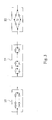
- An AC LED epitaxial chip including more than two LED electronic elements may be used for the AC LED epitaxial chip 22 to provide brighter illumination.
- Fig. 3 provides three such AC LED epitaxial chips 22.
- the first one in the left includes two LED strings parallel connected in opposite directions between two pins of the AC LED epitaxial chips 22, each LED string having two or more LED electronic elements.
- the second case in the middle includes two or more pairs of LED electronic elements serially connected between two pins of the AC LED epitaxial chips 22, each pair of LED electronic elements parallel connected in opposite directions to each other.
- the last case in the right includes five or more LED electronic elements having a bridge configuration between two pins of the AC LED epitaxial chips 22. There have been commercial products can be selected for these cases.
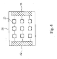
- a filament includes nine AC LED devices 20 bounded on a circuit board 28 in such a manner that three rows of AC LED devices 20 are connected in parallel between solder pads 52 and 54 on the circuit board 28, and each row includes three AC LED devices 20. If each of the AC LED devices 20 operates at a power of 1 W, the filament shown in Fig. 4 can operate at a power as high as 9 W.
- Fig. 5 provides a second embodiment according to the present invention, in which a circuit board 28 has a through hole 60, a thermally conductive member 50 passes through the through hole 60 and has a first end above the circuit board 28 and a second end buried in a thermally conductive electric insulator 36, and an AC LED device 20 having a plastic leaded chip carrier (PLCC) package structure is bounded to the first end of the thermally conductive member 50.
- the thermally conductive member 50 has two strips 56 and two flanges 58. Each of the strips 56 has an axial length ranging from 0.1 to 10 cm, preferably ranging from 0.5 to 3.0 cm. The flanges 58 are sandwiched between the AC LED device 20 and the circuit board 28.
- the circuit board 28 has through holes 62 to be soldered with the pins of the AC LED device 20 by means of solder 68, and through holes 64 to be soldered to an electrode 12 by means of solder 70.
- the through holes 62 and 64 may be replaced by blind holes or other structures, as is well known in the art of circuit board.
- a resistor 30 is soldered between an electrode 14 and the circuit board 28 such that the resistor 30 and the AC LED device 20 are connected in series between the electrodes 12 and 14.
- the circuit board 28 has a glass fiber reinforced substrate or a metal substrate.
- the circuit board 28 is also in mechanical contact with the thermally conductive electric insulator 36.
- the resistor 30 is bounded on the circuit board 28.
- a second resistor is bounded on the circuit board 28 and connected with the first resistor 30 in series.
- the resistor bounded on the circuit board 28 may be a variable resistor.
- the LED lamp in this embodiment is provided with a lamp cover 40, as in the previous embodiment.
- Fig. 6 provides a third embodiment according to the present invention, in which an AC LED device 20 is bounded to a circuit board 28 with a COB package structure, and the circuit board 28 is attached on a thermally conductive electric insulator 36.
- the circuit board 28 has an aluminum metal layer 72, a copper metal layer 76, and a thermally conductive layer 74 sandwiched therebetween, and this structure exhibits better heat dissipation capability than a glass fiber reinforced substrate.
- the circuit board 28 is soldered to an electrode 12 by solder 70, and a resistor 30 is soldered between an electrode 14 and the circuit board 28, such that the resistor 30 and the AC LED device 20 are connected in series between the electrodes 12 and 14.
- the resistor 30 is bounded on the circuit board 28.
- a second resistor is bounded on the circuit board 28 and serially connected to the first resistor 30.
- the resistor bounded on the circuit board 28 may be a variable resistor.
- the LED lamp is provided with a lamp cover, as in the previous embodiment.
- the AC LED device 20 may be a SMD that is bounded on the circuit board 28 by surface mounting technology (SMT).
- the AC LED device 20 having a rated power ranging from 0.3 to 5 W, preferably from 1 to 3 W, and the resistor 30 preferably having a resistance ranging from 50 to 50,000 ⁇ .
- the AC LED device 20 having a rated input voltage ranging from 12 to 240 V.
- the rated input voltage of the AC LED device 20 is selected to be 110 or 220 V, depending on the power lines in its application.
- the rated input voltage of each AC LED device 20 is selected to be smaller, for example 12 V.
Landscapes
- Engineering & Computer Science (AREA)
- General Engineering & Computer Science (AREA)
- Physics & Mathematics (AREA)
- Microelectronics & Electronic Packaging (AREA)
- Optics & Photonics (AREA)
- Non-Portable Lighting Devices Or Systems Thereof (AREA)
Applications Claiming Priority (1)
| Application Number | Priority Date | Filing Date | Title |
|---|---|---|---|
| TW098115441A TW201041426A (en) | 2009-05-08 | 2009-05-08 | LED lamp and manufacturing method thereof |
Publications (2)
| Publication Number | Publication Date |
|---|---|
| EP2249078A1 true EP2249078A1 (fr) | 2010-11-10 |
| EP2249078B1 EP2249078B1 (fr) | 2015-04-29 |
Family
ID=42651441
Family Applications (1)
| Application Number | Title | Priority Date | Filing Date |
|---|---|---|---|
| EP20100159411 Not-in-force EP2249078B1 (fr) | 2009-05-08 | 2010-04-08 | Lampe DEL améliorée à dissipation de chaleur |
Country Status (2)
| Country | Link |
|---|---|
| EP (1) | EP2249078B1 (fr) |
| TW (1) | TW201041426A (fr) |
Cited By (5)
| Publication number | Priority date | Publication date | Assignee | Title |
|---|---|---|---|---|
| GB2490755A (en) * | 2011-05-03 | 2012-11-14 | Gixia Group Co | LED bulb having electro-conductive plastic lamp seat |
| WO2015131417A1 (fr) * | 2014-03-05 | 2015-09-11 | 游宇 | Ampoule à del |
| US9202996B2 (en) | 2012-11-30 | 2015-12-01 | Corning Incorporated | LED lighting devices with quantum dot glass containment plates |
| US10158057B2 (en) | 2010-10-28 | 2018-12-18 | Corning Incorporated | LED lighting devices |
| WO2024040763A1 (fr) * | 2022-08-26 | 2024-02-29 | 深圳市神牛摄影器材有限公司 | Lampe pour photographie et enregistrement vidéo |
Families Citing this family (1)
| Publication number | Priority date | Publication date | Assignee | Title |
|---|---|---|---|---|
| CN107339300B (zh) * | 2014-09-28 | 2022-02-08 | 嘉兴山蒲照明电器有限公司 | 一种用于制造led直管灯的外部加热设备 |
Citations (4)
| Publication number | Priority date | Publication date | Assignee | Title |
|---|---|---|---|---|
| GB2098714A (en) * | 1980-06-04 | 1982-11-24 | Tranilamp Ltd | LED cluster assembly |
| EP1117135A2 (fr) * | 2000-01-12 | 2001-07-18 | Oxley Developments Company Limited | Boítier de Led |
| JP2004186109A (ja) * | 2002-12-06 | 2004-07-02 | Toshiba Lighting & Technology Corp | 発光ダイオード光源及び発光ダイオード照明器具 |
| EP2053301A1 (fr) * | 2007-10-23 | 2009-04-29 | Mafelec | Lampe à diode électroluminescente |
Family Cites Families (3)
| Publication number | Priority date | Publication date | Assignee | Title |
|---|---|---|---|---|
| CN100480577C (zh) * | 2004-10-01 | 2009-04-22 | 沈锦祥 | 一种发光二极管射灯 |
| CN1859821A (zh) * | 2005-05-08 | 2006-11-08 | 卢国文 | 交流电直接驱动的发光二极管照明装置 |
| JP4922607B2 (ja) * | 2005-12-08 | 2012-04-25 | スタンレー電気株式会社 | Led光源装置 |
-
2009
- 2009-05-08 TW TW098115441A patent/TW201041426A/zh unknown
-
2010
- 2010-04-08 EP EP20100159411 patent/EP2249078B1/fr not_active Not-in-force
Patent Citations (4)
| Publication number | Priority date | Publication date | Assignee | Title |
|---|---|---|---|---|
| GB2098714A (en) * | 1980-06-04 | 1982-11-24 | Tranilamp Ltd | LED cluster assembly |
| EP1117135A2 (fr) * | 2000-01-12 | 2001-07-18 | Oxley Developments Company Limited | Boítier de Led |
| JP2004186109A (ja) * | 2002-12-06 | 2004-07-02 | Toshiba Lighting & Technology Corp | 発光ダイオード光源及び発光ダイオード照明器具 |
| EP2053301A1 (fr) * | 2007-10-23 | 2009-04-29 | Mafelec | Lampe à diode électroluminescente |
Cited By (6)
| Publication number | Priority date | Publication date | Assignee | Title |
|---|---|---|---|---|
| US10158057B2 (en) | 2010-10-28 | 2018-12-18 | Corning Incorporated | LED lighting devices |
| GB2490755A (en) * | 2011-05-03 | 2012-11-14 | Gixia Group Co | LED bulb having electro-conductive plastic lamp seat |
| US9202996B2 (en) | 2012-11-30 | 2015-12-01 | Corning Incorporated | LED lighting devices with quantum dot glass containment plates |
| WO2015131417A1 (fr) * | 2014-03-05 | 2015-09-11 | 游宇 | Ampoule à del |
| WO2024040763A1 (fr) * | 2022-08-26 | 2024-02-29 | 深圳市神牛摄影器材有限公司 | Lampe pour photographie et enregistrement vidéo |
| GB2638903A (en) * | 2022-08-26 | 2025-09-03 | Godox Photo Equipment Co Ltd | Lamp for photography and video recording |
Also Published As
| Publication number | Publication date |
|---|---|
| TW201041426A (en) | 2010-11-16 |
| EP2249078B1 (fr) | 2015-04-29 |
| TWI507633B (fr) | 2015-11-11 |
Similar Documents
| Publication | Publication Date | Title |
|---|---|---|
| US8465177B2 (en) | Heat dissipation enhanced LED lamp | |
| US8410699B2 (en) | Heat dissipation enhanced LED lamp | |
| US20100320892A1 (en) | Heat dissipation enhanced led lamp for spotlight | |
| US8587011B2 (en) | Light-emitting device, light-emitting module, and lamp | |
| US8408747B2 (en) | Light emitting devices having heat-dissipating surface | |
| US8337048B2 (en) | Light source package having a six sided light emitting die supported by electrodes | |
| JP4866975B2 (ja) | Ledランプおよび照明器具 | |
| JP2008034140A (ja) | Led照明装置 | |
| EP2249078B1 (fr) | Lampe DEL améliorée à dissipation de chaleur | |
| JP5849238B2 (ja) | ランプ及び照明装置 | |
| US20140016324A1 (en) | Illuminant device | |
| US20140016316A1 (en) | Illuminant device | |
| CN102192411B (zh) | 强化散热的led灯 | |
| JP6788784B2 (ja) | 照明用光源及び照明装置 | |
| US8403720B2 (en) | Assembly method of a LED lamp | |
| JP6910013B2 (ja) | 照明用光源及び照明装置 | |
| CN204853000U (zh) | 发光元件及发光装置 | |
| JP2014139954A (ja) | Ledライト及びその製造方法 | |
| TWI482929B (zh) | Strengthen the heat of the LED lights | |
| TWI518283B (zh) | 發光二極體燈泡 | |
| WO2014045522A1 (fr) | Source d'éclairage et dispositif d'éclairage | |
| GB2466789A (en) | a light emitting diode lamp with heat dissipating wall | |
| JP2012156050A (ja) | Ledライト及びその製造方法 | |
| JP3191670U (ja) | Ledランプ | |
| TWM383090U (en) | LED lamp with enhanced heat dissipation |
Legal Events
| Date | Code | Title | Description |
|---|---|---|---|
| PUAI | Public reference made under article 153(3) epc to a published international application that has entered the european phase |
Free format text: ORIGINAL CODE: 0009012 |
|
| 17P | Request for examination filed |
Effective date: 20100507 |
|
| AK | Designated contracting states |
Kind code of ref document: A1 Designated state(s): AT BE BG CH CY CZ DE DK EE ES FI FR GB GR HR HU IE IS IT LI LT LU LV MC MK MT NL NO PL PT RO SE SI SK SM TR |
|
| AX | Request for extension of the european patent |
Extension state: AL BA ME RS |
|
| 17Q | First examination report despatched |
Effective date: 20120730 |
|
| RIC1 | Information provided on ipc code assigned before grant |
Ipc: F21V 29/00 20060101AFI20140205BHEP Ipc: F21K 99/00 20100101ALI20140205BHEP Ipc: F21Y 101/02 20060101ALN20140205BHEP |
|
| RIC1 | Information provided on ipc code assigned before grant |
Ipc: F21V 29/00 20060101AFI20141006BHEP Ipc: F21Y 101/02 20060101ALN20141006BHEP Ipc: F21K 99/00 20100101ALI20141006BHEP |
|
| GRAP | Despatch of communication of intention to grant a patent |
Free format text: ORIGINAL CODE: EPIDOSNIGR1 |
|
| INTG | Intention to grant announced |
Effective date: 20141124 |
|
| GRAS | Grant fee paid |
Free format text: ORIGINAL CODE: EPIDOSNIGR3 |
|
| GRAA | (expected) grant |
Free format text: ORIGINAL CODE: 0009210 |
|
| AK | Designated contracting states |
Kind code of ref document: B1 Designated state(s): AT BE BG CH CY CZ DE DK EE ES FI FR GB GR HR HU IE IS IT LI LT LU LV MC MK MT NL NO PL PT RO SE SI SK SM TR |
|
| REG | Reference to a national code |
Ref country code: GB Ref legal event code: FG4D |
|
| REG | Reference to a national code |
Ref country code: CH Ref legal event code: EP |
|
| REG | Reference to a national code |
Ref country code: AT Ref legal event code: REF Ref document number: 724645 Country of ref document: AT Kind code of ref document: T Effective date: 20150515 |
|
| REG | Reference to a national code |
Ref country code: IE Ref legal event code: FG4D |
|
| REG | Reference to a national code |
Ref country code: DE Ref legal event code: R096 Ref document number: 602010024245 Country of ref document: DE Effective date: 20150611 |
|
| REG | Reference to a national code |
Ref country code: NL Ref legal event code: VDEP Effective date: 20150429 |
|
| REG | Reference to a national code |
Ref country code: AT Ref legal event code: MK05 Ref document number: 724645 Country of ref document: AT Kind code of ref document: T Effective date: 20150429 |
|
| REG | Reference to a national code |
Ref country code: LT Ref legal event code: MG4D |
|
| PG25 | Lapsed in a contracting state [announced via postgrant information from national office to epo] |
Ref country code: NL Free format text: LAPSE BECAUSE OF FAILURE TO SUBMIT A TRANSLATION OF THE DESCRIPTION OR TO PAY THE FEE WITHIN THE PRESCRIBED TIME-LIMIT Effective date: 20150429 |
|
| PG25 | Lapsed in a contracting state [announced via postgrant information from national office to epo] |
Ref country code: LT Free format text: LAPSE BECAUSE OF FAILURE TO SUBMIT A TRANSLATION OF THE DESCRIPTION OR TO PAY THE FEE WITHIN THE PRESCRIBED TIME-LIMIT Effective date: 20150429 Ref country code: PT Free format text: LAPSE BECAUSE OF FAILURE TO SUBMIT A TRANSLATION OF THE DESCRIPTION OR TO PAY THE FEE WITHIN THE PRESCRIBED TIME-LIMIT Effective date: 20150831 Ref country code: FI Free format text: LAPSE BECAUSE OF FAILURE TO SUBMIT A TRANSLATION OF THE DESCRIPTION OR TO PAY THE FEE WITHIN THE PRESCRIBED TIME-LIMIT Effective date: 20150429 Ref country code: ES Free format text: LAPSE BECAUSE OF FAILURE TO SUBMIT A TRANSLATION OF THE DESCRIPTION OR TO PAY THE FEE WITHIN THE PRESCRIBED TIME-LIMIT Effective date: 20150429 Ref country code: HR Free format text: LAPSE BECAUSE OF FAILURE TO SUBMIT A TRANSLATION OF THE DESCRIPTION OR TO PAY THE FEE WITHIN THE PRESCRIBED TIME-LIMIT Effective date: 20150429 Ref country code: NO Free format text: LAPSE BECAUSE OF FAILURE TO SUBMIT A TRANSLATION OF THE DESCRIPTION OR TO PAY THE FEE WITHIN THE PRESCRIBED TIME-LIMIT Effective date: 20150729 |
|
| PG25 | Lapsed in a contracting state [announced via postgrant information from national office to epo] |
Ref country code: IS Free format text: LAPSE BECAUSE OF FAILURE TO SUBMIT A TRANSLATION OF THE DESCRIPTION OR TO PAY THE FEE WITHIN THE PRESCRIBED TIME-LIMIT Effective date: 20150829 Ref country code: GR Free format text: LAPSE BECAUSE OF FAILURE TO SUBMIT A TRANSLATION OF THE DESCRIPTION OR TO PAY THE FEE WITHIN THE PRESCRIBED TIME-LIMIT Effective date: 20150730 Ref country code: AT Free format text: LAPSE BECAUSE OF FAILURE TO SUBMIT A TRANSLATION OF THE DESCRIPTION OR TO PAY THE FEE WITHIN THE PRESCRIBED TIME-LIMIT Effective date: 20150429 Ref country code: LV Free format text: LAPSE BECAUSE OF FAILURE TO SUBMIT A TRANSLATION OF THE DESCRIPTION OR TO PAY THE FEE WITHIN THE PRESCRIBED TIME-LIMIT Effective date: 20150429 |
|
| PG25 | Lapsed in a contracting state [announced via postgrant information from national office to epo] |
Ref country code: EE Free format text: LAPSE BECAUSE OF FAILURE TO SUBMIT A TRANSLATION OF THE DESCRIPTION OR TO PAY THE FEE WITHIN THE PRESCRIBED TIME-LIMIT Effective date: 20150429 Ref country code: DK Free format text: LAPSE BECAUSE OF FAILURE TO SUBMIT A TRANSLATION OF THE DESCRIPTION OR TO PAY THE FEE WITHIN THE PRESCRIBED TIME-LIMIT Effective date: 20150429 |
|
| REG | Reference to a national code |
Ref country code: DE Ref legal event code: R097 Ref document number: 602010024245 Country of ref document: DE |
|
| PG25 | Lapsed in a contracting state [announced via postgrant information from national office to epo] |
Ref country code: PL Free format text: LAPSE BECAUSE OF FAILURE TO SUBMIT A TRANSLATION OF THE DESCRIPTION OR TO PAY THE FEE WITHIN THE PRESCRIBED TIME-LIMIT Effective date: 20150429 Ref country code: SK Free format text: LAPSE BECAUSE OF FAILURE TO SUBMIT A TRANSLATION OF THE DESCRIPTION OR TO PAY THE FEE WITHIN THE PRESCRIBED TIME-LIMIT Effective date: 20150429 Ref country code: RO Free format text: LAPSE BECAUSE OF NON-PAYMENT OF DUE FEES Effective date: 20150429 Ref country code: CZ Free format text: LAPSE BECAUSE OF FAILURE TO SUBMIT A TRANSLATION OF THE DESCRIPTION OR TO PAY THE FEE WITHIN THE PRESCRIBED TIME-LIMIT Effective date: 20150429 |
|
| PLBE | No opposition filed within time limit |
Free format text: ORIGINAL CODE: 0009261 |
|
| STAA | Information on the status of an ep patent application or granted ep patent |
Free format text: STATUS: NO OPPOSITION FILED WITHIN TIME LIMIT |
|
| 26N | No opposition filed |
Effective date: 20160201 |
|
| REG | Reference to a national code |
Ref country code: FR Ref legal event code: PLFP Year of fee payment: 7 |
|
| PG25 | Lapsed in a contracting state [announced via postgrant information from national office to epo] |
Ref country code: IT Free format text: LAPSE BECAUSE OF FAILURE TO SUBMIT A TRANSLATION OF THE DESCRIPTION OR TO PAY THE FEE WITHIN THE PRESCRIBED TIME-LIMIT Effective date: 20150429 |
|
| PG25 | Lapsed in a contracting state [announced via postgrant information from national office to epo] |
Ref country code: SI Free format text: LAPSE BECAUSE OF FAILURE TO SUBMIT A TRANSLATION OF THE DESCRIPTION OR TO PAY THE FEE WITHIN THE PRESCRIBED TIME-LIMIT Effective date: 20150429 |
|
| PG25 | Lapsed in a contracting state [announced via postgrant information from national office to epo] |
Ref country code: BE Free format text: LAPSE BECAUSE OF FAILURE TO SUBMIT A TRANSLATION OF THE DESCRIPTION OR TO PAY THE FEE WITHIN THE PRESCRIBED TIME-LIMIT Effective date: 20150429 |
|
| REG | Reference to a national code |
Ref country code: CH Ref legal event code: PL |
|
| PG25 | Lapsed in a contracting state [announced via postgrant information from national office to epo] |
Ref country code: LU Free format text: LAPSE BECAUSE OF FAILURE TO SUBMIT A TRANSLATION OF THE DESCRIPTION OR TO PAY THE FEE WITHIN THE PRESCRIBED TIME-LIMIT Effective date: 20160408 |
|
| REG | Reference to a national code |
Ref country code: IE Ref legal event code: MM4A |
|
| PG25 | Lapsed in a contracting state [announced via postgrant information from national office to epo] |
Ref country code: LI Free format text: LAPSE BECAUSE OF NON-PAYMENT OF DUE FEES Effective date: 20160430 Ref country code: CH Free format text: LAPSE BECAUSE OF NON-PAYMENT OF DUE FEES Effective date: 20160430 |
|
| REG | Reference to a national code |
Ref country code: FR Ref legal event code: PLFP Year of fee payment: 8 |
|
| PG25 | Lapsed in a contracting state [announced via postgrant information from national office to epo] |
Ref country code: IE Free format text: LAPSE BECAUSE OF NON-PAYMENT OF DUE FEES Effective date: 20160408 |
|
| PG25 | Lapsed in a contracting state [announced via postgrant information from national office to epo] |
Ref country code: SE Free format text: LAPSE BECAUSE OF FAILURE TO SUBMIT A TRANSLATION OF THE DESCRIPTION OR TO PAY THE FEE WITHIN THE PRESCRIBED TIME-LIMIT Effective date: 20150429 |
|
| REG | Reference to a national code |
Ref country code: FR Ref legal event code: PLFP Year of fee payment: 9 |
|
| PG25 | Lapsed in a contracting state [announced via postgrant information from national office to epo] |
Ref country code: SM Free format text: LAPSE BECAUSE OF FAILURE TO SUBMIT A TRANSLATION OF THE DESCRIPTION OR TO PAY THE FEE WITHIN THE PRESCRIBED TIME-LIMIT Effective date: 20150429 Ref country code: HU Free format text: LAPSE BECAUSE OF FAILURE TO SUBMIT A TRANSLATION OF THE DESCRIPTION OR TO PAY THE FEE WITHIN THE PRESCRIBED TIME-LIMIT; INVALID AB INITIO Effective date: 20100408 Ref country code: CY Free format text: LAPSE BECAUSE OF FAILURE TO SUBMIT A TRANSLATION OF THE DESCRIPTION OR TO PAY THE FEE WITHIN THE PRESCRIBED TIME-LIMIT Effective date: 20150429 |
|
| PG25 | Lapsed in a contracting state [announced via postgrant information from national office to epo] |
Ref country code: MT Free format text: LAPSE BECAUSE OF NON-PAYMENT OF DUE FEES Effective date: 20160430 Ref country code: MK Free format text: LAPSE BECAUSE OF FAILURE TO SUBMIT A TRANSLATION OF THE DESCRIPTION OR TO PAY THE FEE WITHIN THE PRESCRIBED TIME-LIMIT Effective date: 20150429 Ref country code: TR Free format text: LAPSE BECAUSE OF FAILURE TO SUBMIT A TRANSLATION OF THE DESCRIPTION OR TO PAY THE FEE WITHIN THE PRESCRIBED TIME-LIMIT Effective date: 20150429 Ref country code: MC Free format text: LAPSE BECAUSE OF FAILURE TO SUBMIT A TRANSLATION OF THE DESCRIPTION OR TO PAY THE FEE WITHIN THE PRESCRIBED TIME-LIMIT Effective date: 20150429 |
|
| PG25 | Lapsed in a contracting state [announced via postgrant information from national office to epo] |
Ref country code: BG Free format text: LAPSE BECAUSE OF FAILURE TO SUBMIT A TRANSLATION OF THE DESCRIPTION OR TO PAY THE FEE WITHIN THE PRESCRIBED TIME-LIMIT Effective date: 20150429 |
|
| RIC2 | Information provided on ipc code assigned after grant |
Ipc: F21Y 101/02 20000101ALN20141006BHEP Ipc: F21V 29/00 20150101AFI20141006BHEP Ipc: F21K 99/00 20160101ALI20141006BHEP |
|
| PGFP | Annual fee paid to national office [announced via postgrant information from national office to epo] |
Ref country code: GB Payment date: 20240308 Year of fee payment: 15 |
|
| PGFP | Annual fee paid to national office [announced via postgrant information from national office to epo] |
Ref country code: FR Payment date: 20240308 Year of fee payment: 15 |
|
| PGFP | Annual fee paid to national office [announced via postgrant information from national office to epo] |
Ref country code: DE Payment date: 20240426 Year of fee payment: 15 |
|
| REG | Reference to a national code |
Ref country code: DE Ref legal event code: R119 Ref document number: 602010024245 Country of ref document: DE |
|
| GBPC | Gb: european patent ceased through non-payment of renewal fee |
Effective date: 20250408 |
|
| PG25 | Lapsed in a contracting state [announced via postgrant information from national office to epo] |
Ref country code: DE Free format text: LAPSE BECAUSE OF NON-PAYMENT OF DUE FEES Effective date: 20251104 |
|
| PG25 | Lapsed in a contracting state [announced via postgrant information from national office to epo] |
Ref country code: GB Free format text: LAPSE BECAUSE OF NON-PAYMENT OF DUE FEES Effective date: 20250408 |
|
| PG25 | Lapsed in a contracting state [announced via postgrant information from national office to epo] |
Ref country code: FR Free format text: LAPSE BECAUSE OF NON-PAYMENT OF DUE FEES Effective date: 20250430 |