EP2249093A1 - Appareil de gestion de climatiseur - Google Patents
Appareil de gestion de climatiseur Download PDFInfo
- Publication number
- EP2249093A1 EP2249093A1 EP09703872A EP09703872A EP2249093A1 EP 2249093 A1 EP2249093 A1 EP 2249093A1 EP 09703872 A EP09703872 A EP 09703872A EP 09703872 A EP09703872 A EP 09703872A EP 2249093 A1 EP2249093 A1 EP 2249093A1
- Authority
- EP
- European Patent Office
- Prior art keywords
- screen
- unit
- indoor units
- air conditioner
- managing apparatus
- Prior art date
- Legal status (The legal status is an assumption and is not a legal conclusion. Google has not performed a legal analysis and makes no representation as to the accuracy of the status listed.)
- Withdrawn
Links
Images


Classifications
-
- F—MECHANICAL ENGINEERING; LIGHTING; HEATING; WEAPONS; BLASTING
- F24—HEATING; RANGES; VENTILATING
- F24F—AIR-CONDITIONING; AIR-HUMIDIFICATION; VENTILATION; USE OF AIR CURRENTS FOR SCREENING
- F24F11/00—Control or safety arrangements
- F24F11/30—Control or safety arrangements for purposes related to the operation of the system, e.g. for safety or monitoring
- F24F11/32—Responding to malfunctions or emergencies
-
- F—MECHANICAL ENGINEERING; LIGHTING; HEATING; WEAPONS; BLASTING
- F24—HEATING; RANGES; VENTILATING
- F24F—AIR-CONDITIONING; AIR-HUMIDIFICATION; VENTILATION; USE OF AIR CURRENTS FOR SCREENING
- F24F11/00—Control or safety arrangements
- F24F11/50—Control or safety arrangements characterised by user interfaces or communication
- F24F11/52—Indication arrangements, e.g. displays
-
- F—MECHANICAL ENGINEERING; LIGHTING; HEATING; WEAPONS; BLASTING
- F24—HEATING; RANGES; VENTILATING
- F24F—AIR-CONDITIONING; AIR-HUMIDIFICATION; VENTILATION; USE OF AIR CURRENTS FOR SCREENING
- F24F11/00—Control or safety arrangements
- F24F11/62—Control or safety arrangements characterised by the type of control or by internal processing, e.g. using fuzzy logic, adaptive control or estimation of values
- F24F11/63—Electronic processing
- F24F11/64—Electronic processing using pre-stored data
-
- F—MECHANICAL ENGINEERING; LIGHTING; HEATING; WEAPONS; BLASTING
- F24—HEATING; RANGES; VENTILATING
- F24F—AIR-CONDITIONING; AIR-HUMIDIFICATION; VENTILATION; USE OF AIR CURRENTS FOR SCREENING
- F24F11/00—Control or safety arrangements
- F24F11/50—Control or safety arrangements characterised by user interfaces or communication
- F24F11/54—Control or safety arrangements characterised by user interfaces or communication using one central controller connected to several sub-controllers
-
- F—MECHANICAL ENGINEERING; LIGHTING; HEATING; WEAPONS; BLASTING
- F24—HEATING; RANGES; VENTILATING
- F24F—AIR-CONDITIONING; AIR-HUMIDIFICATION; VENTILATION; USE OF AIR CURRENTS FOR SCREENING
- F24F2140/00—Control inputs relating to system states
- F24F2140/60—Energy consumption
Definitions
- the present invention relates to an air conditioner managing apparatus.
- a multi-type air conditioner which comprises at least one outdoor unit and a plurality of indoor units, is often used in properties such as office buildings.
- a management system is employed (refer to Patent Document 1: Japanese Unexamined Patent Application Publication No. 2003-302092 ) that is provided with an air conditioner managing apparatus, which is for collecting information from the air conditioners in the same property, and that centrally manages the indoor units in the property.
- an administrator of the property must check the information collected by the air conditioner managing apparatus about all of the indoor units so that he or she can specify an indoor unit with some kind of problem and check the details thereof.
- the information about the indoor units with no problems and whose information does not need to be checked is also checked, which makes the work troublesome.
- An object of the present invention is to provide an air conditioner managing apparatus that, in a property such as an office building wherein a plurality of indoor units are installed, facilitates the work of specifying an indoor unit with a problem and checking the details thereof.
- An air conditioner managing apparatus comprises a storage unit, a first screen generating unit, a second screen generating unit, and a display switching unit.
- the storage unit accumulates operation data about numerous indoor units.
- the first screen generating unit generates a first screen wherein a plurality of indoor units-among target indoor units-with a problem can be visually verified based on the operation data.
- the second screen generating unit generates a second screen wherein the operation data related to one specific indoor unit can be visually verified.
- operation data about numerous indoor units is accumulated, and a first screen is generated wherein a plurality of indoor units-among target indoor units-with a problem can be visually verified.
- a second screen is generated wherein the operation data related to one specific indoor unit can be visually verified.
- An air conditioner managing apparatus is the air conditioner managing apparatus according to the first aspect of the present invention, and further comprises an identifying unit.
- the identifying unit identifies the plurality of the indoor units with the problem based on each viewpoint of a plurality of viewpoints.
- the first screen switchably displays, by viewpoint, the plurality of the indoor units with the problem.
- the indoor units with the problem are identified based on each viewpoint of a plurality of viewpoints, and the indoor units with the problem are displayed, switchably by viewpoint, on the first screen.
- the plurality of viewpoints includes excessive consumption of electric power, long-time operation, reduced comfort, and the like.
- An air conditioner managing apparatus is the air conditioner managing apparatus according to the second aspect of the present invention, wherein the second screen switchably displays, based on the operation data, an operation status display screen that indicates an operation status of one indoor unit and an occurrence day display screen that indicates the problem occurrence day of the one indoor unit.
- the operation data display screen displays the operation data of an identified indoor unit
- the occurrence day display screen displays the problem occurrence day.
- An air conditioner managing apparatus is the air conditioner managing apparatus according to the third aspect of the present invention, wherein the second screen displays a graph that aggregates the operation data in accordance with the plurality of viewpoints.
- the second screen displays a graph that aggregates the operation data of one indoor unit in accordance with the plurality of viewpoints.
- An air conditioner managing apparatus is the air conditioner managing apparatus according to the fourth aspect of the present invention, wherein the operation status includes an average operation status of the one indoor unit during a prescribed interval and the operation status of the one indoor unit during a prescribed day within the prescribed interval; and the second screen displays, side by side, a graph that indicates the average operation status during the interval and a graph that indicates the operation status for the prescribed day.
- the second screen displays, side by side, a graph that indicates the average operation status during the interval and a graph that indicates the operation status for the prescribed day.
- An air conditioner managing apparatus is the air conditioner managing apparatus according to any one aspect of the third through fifth aspects of the present invention, wherein the second screen displays a method of correcting the problem based on the operation status.
- the indoor unit with a problem and the method of correcting that indoor unit's problem are displayed, which makes it possible to effectively manage the indoor unit.
- An air conditioner managing apparatus is the air conditioner managing apparatus according to the sixth aspect of the present invention, wherein the first screen includes a distribution diagram that indicates the distribution of the indoor units based on the problem severity.
- the distribution of the identified indoor units based on problem severity is displayed.
- An air conditioner managing apparatus is the air conditioner managing apparatus according to the seventh aspect of the present invention and further comprises an input unit that inputs an identification condition for identifying the plurality of the indoor units with the problem.
- the plurality of the indoor units with the problem is identified based on an identification condition input by the input unit.
- the air conditioner managing apparatus it is possible to easily specify the indoor units with a problem based on the operation data related to a plurality of indoor units; furthermore, detailed information can be easily checked.
- the air conditioner managing apparatus In the air conditioner managing apparatus according to the third aspect of the present invention, it is possible to easily check the problem occurrence day and the operation data for the problem occurrence day.
- the air conditioner managing apparatus it is possible to visually verify the operation data simultaneously for the plurality of viewpoints; for example, it is possible to grasp the occurrence status (e.g., time slot, severity, etc.), the cause, the correlation, and the like for a plurality of problems.
- the occurrence status e.g., time slot, severity, etc.
- the air conditioner managing apparatus it is possible to easily compare the average operation data during the interval and the operation data for the prescribed day; for example, it is possible to grasp the problem occurrence frequency, the problem severity for one day, and the like.
- the air conditioner managing apparatus it is possible to visually grasp the number of indoor units with a problem and the severity of that problem.
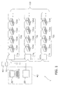
- FIG. 1 shows the configuration of the air conditioner managing system of the present embodiment in a property 1.
- the property 1 is a building, such as an office building or a tenant building, wherein a plurality of air conditioners 10a , 10b, 10c, ... and an air conditioner managing apparatus 40 are installed.
- Each of the air conditioners 10a, 10b, 10c, ... is a multi-type air conditioner that comprises one outdoor unit and a plurality of indoor units connected to the outdoor unit.
- a power supply 60 is connected to outdoor units 11a, 11b , 11c , ..., and electric power from the power supply 60 is supplied to the air conditioners 10a, 10b, 10c, ... via electric power supply lines.
- An electric power meter 70 which is provided in the electric power supply line that connects the power supply 60 and the outdoor units 11a , 11b , 11c , ...., measures the electric power supplied to the air conditioners 10a, 10b, 10c, ... (i.e., the total electric power consumption).
- the air conditioner managing apparatus 40 identifies-among numerous indoor units 12aa-12ad, 12ba-12bd, 12ca-12cd, ... installed in the property 1 -those indoor units 12aa-12ad, 12ba-12bd, 12ca-12cd, ... wherein prescribed problems are occurring and, furthermore, displays the details of these problems for each of the indoor units 12aa-12ad, 12ba-12bd, 12ca-12cd, ....
- the prescribed problems are excessive consumption of electric power, long-time operation, and reduced comfort.
- the following text explains the configuration of the air conditioner managing apparatus 40 and each of the problems the air conditioner managing apparatus 40 manages; furthermore, the explanation is based on an illustrative example of a management screen that shows how the air conditioner managing apparatus 40 manages each of the problems.
- the air conditioner managing apparatus 40 comprises a local controller 20, which is connected to the outdoor units 11a , 11b , 11c , ..., and a comprehensive managing apparatus 30, which is connected to the local controller 20.
- the local controller 20 acquires operation data about the plurality of indoor units 12aa-12ad, 12ba-12bd, 12ca-12cd, ... via the outdoor units 11a , 11b , 11c , ....
- the comprehensive managing apparatus 30 comprehensively manages the operation data the local controller 20 acquires.
- operation data is data related to either an operation history or an operation state.
- the data related to the operation history refers to information about a power supply ON/OFF state, a thermostat ON/OFF state, an operation mode (i.e., a cooling mode, a heating mode, a ventilating mode, and the like), a set temperature, an indoor temperature (i.e., an inlet temperature), and the like of the indoor units 12aa-12ad, 12ba-12bd, 12ca-12cd, ... connected to the outdoor units 11a , 11b , 11c , ....
- the data related to the operation state are values detected by various sensors attached to the air conditioners 10a, 10b, 10c, ....
- the operation time in the present embodiment is, specifically, the thermostat ON time of the indoor units 12aa-12ad, 12ba-12bd, 12ca-12cd, ....
- the thermostat ON time is the time during which the indoor units 12aa-12ad, 12ba-12bd, 12ca-12cd, ... supply cooling or heat.
- the local controller 20 principally comprises a communication unit 21, a storage unit 22, and a control unit 23.
- the communication unit 21 is an input-output port that sends signals to and receives signals from the air conditioners 10a , 10b , 10c, ... and the comprehensive managing apparatus 30.
- the storage unit 22 has an operation data storage area 22a and an electric power consumption value storage area 22b.
- the operation data acquired by an information acquiring unit 23a which is discussed below, from the air conditioners 10a , 10b, 10c, ... is stored in the operation data storage area 22a.
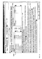
- the operation data storage area 22a is a tabular database, as shown in FIG. 2B , and is provided with fields related to "equipment ID,” "time of day,” “power supply ON/OFF state,” “thermostat ON/OFF state,” “operation mode,” “set temperature,” “indoor temperature,” and “humidity.”
- fields related to the degree of opening of an expansion valve the values detected by various sensors are also provided.
- the operation data storage area 22a has storage capacity capable of storing operation data of a prescribed interval only (in the present embodiment, 30 min.), and operation data outside that interval are successively deleted with every new acquisition of operation data.
- Values related to the total electric power consumption (i.e., total electric power consumption values) of the air conditioners 10a, 10b, 10c, ... measured by the electric power meter 70 are stored in the electric power consumption value storage area 22b.
- the electric power consumption value storage area 22b is also a tabular database, as shown in FIG. 2C , and is provided with fields related to "time of day,” and "total electric power consumption.”
- the storage unit 22 has an area that stores a management program capable of being read and executed by the control unit 23, which is discussed below.
- the control unit 23 principally comprises the information acquiring unit 23a and a transmission unit 23b.
- the information acquiring unit 23a acquires at prescribed intervals (in the present embodiment, every minute) operation data from the air conditioners 10a, 10b, 10c, ... via the communication unit 21.
- the transmission unit 23b transmits at prescribed intervals (in the present embodiment, every minute) information stored in the operation data storage area 22a and the electric power consumption value storage area 22b to the comprehensive managing apparatus 30 via the communication unit 21.
- the comprehensive managing apparatus 30 principally comprises a communication unit 31, an input unit 32, a storage unit 33, a control unit 34, and a display unit 35.
- the communication unit 31 is an input-output port that sends signals to and receives signals from the local controller 20.
- the input unit 32 accepts instructions from a user. Upon acceptance of an instruction by the input unit 32, a process corresponding to that instruction is executed by the comprehensive managing apparatus 30 and/or by the local controller 20 via the comprehensive managing apparatus 30. For example, if the input unit 32 accepts an instruction to turn ON the power supply of the air conditioners 10a, 10b, 10c, ..., then a power supply ON instruction is transmitted to the air conditioners 10a, 10b, 10c, ... via the local controller 20. In addition, upon acceptance of an input of a prescribed interval by the input unit 32, an aggregation interval, which is the target interval during which a process is performed by the comprehensive managing apparatus 30 (discussed below), is determined. Furthermore, upon the user's inputting of an instruction to a screen displayed by the display unit 35 (discussed below), the instruction is accepted by the input unit 32.
- the storage unit 33 has an operation data storage area 33a, an electric power consumption value storage area 33b, an average value storage area 33c, a reference value storage area 33d, a corrective action data storage area 33e, and a determined value storage area 33f.
- the operation data storage area 33a stores operation data of the air conditioners 10a, 10b, 10c, ... transmitted from the local controller 20.
- the operation data storage area 33a is a tabular database, as in FIG. 2B , and is provided with fields related to "equipment ID,” "time of day,” “power supply ON/OFF state,” “thermostat ON/OFF state,” “operation mode,” “set temperature,” “indoor temperature,” and “humidity.”
- Information related to electric power consumption is stored in the electric power consumption value storage area 33b.
- the information related to the electric power consumption includes a value related to the total electric power consumption of the air conditioners 10a, 10b, 10c, ... transmitted from the local controller 20 (i.e., the total electric power consumption value) and a value related to the electric power consumption of each of the indoor units 12aa-12ad, 12ba-12bd, 12ca-12cd, ... calculated by an apportioning unit 34a (i.e., the electric power consumption values), which is discussed below.
- the total electric power consumption value is stored in a format identical to that of the total electric power consumption value stored in the electric power consumption value storage area 22b discussed above.
- the database is stored in a tabular database, as shown in FIG. 2C , and the database is provided with fields related to "time of day,” and "total electric power consumption.”
- the values related to the electric power consumption of each of the indoor units 12aa-12ad, 12ba-12bd, 12ca-12cd, ... are also stored in a tabular database, as shown in FIG. 2D , and the database is provided with fields related to "equipment ID,” "electric power consumption,” and "time.”
- the average value storage area 33c is likewise a tabular database, as shown in FIG. 2E , and is provided with fields related to "equipment ID,” "electric power consumption,” and "time.”
- a reference value of the electric power consumption values which is determined by a reference value determining unit 34c (discussed below), is stored in the reference value storage area 33d.
- Corrective action data storage area 33e Data related to a plurality of corrective actions, which is selected by a corrective action selecting unit 34f (discussed below), is stored in the corrective action data storage area 33e.
- the prescribed value that the input unit 32 accepts from the user is stored in the determined value storage area 33f.
- the control unit 34 comprises the apportioning unit 34a, the average value calculating unit 34b, the reference value determining unit 34c, an identifying unit 34d, a correcting unit 34e, the corrective action selecting unit 34f, a first screen generating unit 34g, a second screen generating unit 34h, and a display switching unit 34i.
- the apportioning unit 34a apportions the total electric power consumption value of the air conditioners 10a, 10b, 10c, ... stored in the electric power consumption value storage area 33b among the operation data stored in the operation data storage area 33a and calculates the electric power consumption of each of the indoor units 12aa-12ad, 12ba-12bd, 12ca-12cd, .... Specifically, as shown in Japanese Unexamined Patent Application Publication No.
- the total electric power consumption is apportioned in accordance with information such as the degree of opening of the expansion valve of each of the indoor units 12aa-12ad, 12ba-12bd, 12ca-12cd, and the electric power consumption of each of the indoor units 12aa-12ad, 12ba-12bd, 12ca-12cd, ... is calculated. Furthermore, the electric power consumption values calculated by the apportioning unit 34a are stored in the electric power consumption value storage area 33b discussed above.
- the average value calculating unit 34b calculates the average electric power consumption per day of all of the indoor units 12aa-12ad, 12ba-12bd, 12ca-12cd, ... over the prescribed interval accepted by the input unit 32 discussed above.
- the average value calculated by the average value calculating unit 34b is stored in the average value storage area 33c discussed above.
- the reference value determining unit 34c determines the reference value for determining which of the indoor units 12aa-12ad, 12ba-12bd, 12ca-12cd, ... are consuming a large amount of electric power. This will be explained in detail using the ⁇ Target Problem and Determination Reference> column, which is discussed below. Furthermore, the reference value determined by the reference value determining unit 34c is stored in the reference value storage area 33d discussed above.
- the identifying unit 34d identifies the indoor units 12aa-12ad, 12ba-12bd, 12ca-12cd, ... whose electric power consumption exceeds the reference value. Specifically, the identifying unit 34d compares the average of the electric power consumption per day of each of the indoor units 12aa-12ad, 12ba-12bd, 12ca-12cd, ... over the prescribed interval accepted by the input unit 32 discussed above with the reference value per day over the prescribed interval determined by the reference value determining unit 34c and identifies those indoor units 12aa-12ad, 12ba-12bd, 12ca-12cd, ... whose electric power consumption exceeds the reference value.
- the correcting unit 34e corrects the identification result produced by the identifying unit 34d.
- the correcting unit 34e performs its correction on the identification results for electric power consumption and reduced comfort.
- Correcting the identification result for electric power consumption means correcting the electric power consumption value of each of the indoor units 12aa-12ad, 12ba-12bd, 12ca-12cd, ... , taking into consideration the air conditioning capacity of the identified indoor units 12aa-12ad, 12ba-12bd, 12ca-12cd, ....
- the air conditioning capacity is the horsepower or the capacity (kW), or the like of the indoor units 12aa-12ad, 12ba-12bd, 12ca-12cd, ....
- the correcting unit 34e divides the electric power consumption value of each of the indoor units 12aa-12ad, 12ba-12bd, 12ca-12cd , ... by the horsepower. In the present embodiment, the correction of electric power consumption is performed by default. Correcting the identification result for reduced comfort involves ranking the indoor units 12aa-12ad, 12ba-12bd, 12ca-12cd, ... taking into consideration the rate of occurrence of reduced comfort. In accordance with an instruction, the correcting unit 34e ranks each of the indoor units 12aa-12ad, 12ba-12bd, 12ca-12cd , ... taking into consideration the reduced comfort occurrence rate. Specifically, the equation reduced comfort time ⁇ (reduced comfort time ⁇ operation time) is used to calculate the reduced comfort time taking into consideration the occurrence rate.
- the corrective action selecting unit 34f selects an appropriate corrective action for each problem taking into consideration the operation data, such as the set temperature and the operation time, of the indoor units 12aa-12ad, 12ba-12bd, 12ca-12cd, ... identified by the identifying unit 34d.
- corrective actions include reexamining the set temperature, reexamining the operation schedule, performing a filter inspection, and the like.
- the first screen generating unit 34g Based on the various values stored in the storage unit 33, the first screen generating unit 34g generates a first screen for displaying the information about the identified indoor units 12aa-12ad, 12ba-12bd , 12ca-12cd, ... on the display unit 35.
- the first screen is a screen capable of switching the viewpoint and the indoor units 12aa-12ad, 12ba-12bd, 12ca-12cd, ... identified by that viewpoint.
- tabs that display the identification result of each viewpoint of the plurality of viewpoints i.e., excessive electric power consumption, long-time operation, and reduced comfort
- the first screen corresponds to an identification screen, which is discussed below, and is a screen wherein all of the identified indoor units 12aa-12ad, 12ba-12bd, 12ca-12cd, ... can be visually verified.
- the second screen generating unit 34h generates a second screen, wherein the operation data related to a specific indoor unit of the identified indoor units 12aa-12ad, 12ba-12bd, 12ca-12cd, ... can be visually verified.
- the second screen is a screen capable of switching between a tab that displays an operation status and a tab that displays problem occurrence days, both of which are based on the operation data related to the specific indoor unit.
- a graph is displayed that indicates the average operation status for the interval and the operating status for one day of the specific indoor unit.
- a table is displayed that indicates the problem occurrence days related to the plurality of viewpoints (i.e., excessive electric power consumption, long-time operation, and reduced comfort) of the specific indoor unit.
- a graph that aggregates operating data by the plurality of viewpoints is displayed. The second screen corresponds to a detailed screen, which is discussed below.
- the display switching unit 34i switches the display from the first screen, which is displayed by the display unit 35, to the second screen, which displays the details of the indoor unit selected on the first screen. Namely, in accordance with an instruction from the user, the display switching unit 34i switches the screen displayed by the display unit 35 from the identification screen, which displays the identification results of all of the indoor units, to the detailed screen of the single indoor unit selected on the identification screen.
- the display unit 35 is a display screen for displaying the information received by the comprehensive managing apparatus 30, displaying the first screen, displaying the second screen, and the like.
- the information displayed by the display unit 35 will be explained in detail in the ⁇ Illustrative Example of Management Screen and Operation> section.
- the following text explains the prescribed problems, namely, excessive electric power consumption, long-time operation, and reduced comfort, of the indoor units identified by the air conditioner managing apparatus 40 according to the present embodiment.
- the excessive consumption of electric power means that the electric power consumption value is large.
- the air conditioner managing apparatus 40 determines the reference value related to excessive electric power consumption, identifies the indoor units 12aa-12ad, 12ba-12bd, 12ca-12cd, ... that have consumed amounts of electric power that exceed the reference value, and furthermore displays those identified indoor units 12aa-12ad, 12ba-12bd, 12ca-12cd, ... in descending order based on their electric power consumption value. Furthermore, if their electric power consumption value has been corrected by the correcting unit 34e discussed above, then the order is determined based on the value corrected by the correcting unit 34e.
- y is the reference value of the electric power consumption over the prescribed interval
- x is an average operation time during the interval
- k is a prescribed value determined when identification conditions are set
- a is the slope of the average electric power.
- the average electric power is the straight line approximation calculated using the least squares method for the average electric power consumption during the interval and the average operation time during the interval of each of the indoor units.
- Long-time operation refers to operation wherein a cumulative operation time per day exceeds a prescribed determination value.
- the prescribed determination value is a prescribed value set by the user.
- the air conditioner managing apparatus 40 identifies those indoor units whose long-time operation occurrence day count during the target aggregation interval is greater than or equal to one day and furthermore displays the identified indoor units in descending order based on their long-time operation occurrence day count.
- the method of calculating the long-time operation occurrence day count is first to calculate the one day cumulative operation time (hrs) (i.e., a step S1 ), and next to determine whether the cumulative operation time is greater than or equal to the prescribed determination value (i.e., a step S2).
- step S2 if the cumulative operation time is greater than or equal to the determination value, then one day is added to the long-time operation occurrence day count (i.e., a step S3). In step S2, if the cumulative operation time is less than the determination value, then the day count is not incremented.
- Reduced comfort refers to cases wherein an inlet temperature does not reach a temperature set in the indoor unit and to a state wherein a value of the difference between the average inlet temperature per hour and the average set temperature per hour is greater than or equal to the prescribed determination value.
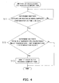
- the air conditioner managing apparatus 40 identifies those indoor units wherein the reduced comfort state was greater than or equal to one hour during the target aggregation interval and furthermore displays the identified indoor units in order of the length of time spent in the reduced comfort state. Furthermore, if the correcting unit 34e discussed above made a correction, then the order is determined based on the corrected value by the correcting unit 34e. In the method of calculating the reduced comfort time, as shown in FIG .
- the method determines whether the thermostat ON time continued for 60 min. or longer (i.e., a step S11 ). If the thermostat ON time did continue for 60 min. or longer, then it means that the state wherein the inlet temperature did not reach the set temperature also continued for 60 min. or longer. In the step S11 , if the thermostat ON time did continue for 60 min. or longer, then the method determines whether the difference between the inlet temperature and the set temperature is greater than or equal to the prescribed determination value (i.e., a step S12 ). In the step S12 , if the difference between the inlet temperature and the set temperature is greater than or equal to the determination value, then one hour is added to the reduced comfort time (i.e., a step S13 ).
- FIG. 5 shows an identification screen wherein the indoor units 12aa-12ad, 12ba-12bd, 12ca-12cd, ... with a problem are identified.
- the identification screen identifies those indoor units with a problem from the three viewpoints of excessive electric power consumption, long-time operation, and reduced comfort discussed above.
- the excessive electric power consumption tab is selected, and the indoor units 12aa-12ad, 12ba-12bd, 12ca-12cd , ... whose electric power consumption values are large are identified.
- aggregation is performed for the period beginning on August 1, 2007 (Wed.) and ending on August 31, 2007 (Fri.).
- the aggregation interval which is set by default to the most recent two weeks, can be changed by the user. Furthermore, when identifying the indoor units 12aa-12ad, 12ba-12bd, 12ca-12cd, ..., the user can select a target group (refer to a symbol 503). Here, if the average electric power consumption per day during the aggregation interval of the indoor units 12aa-12ad, 12ba-12bd, 12ca-12cd, ... that belong to the selected group exceeds the reference value, then those indoor units that exceed the reference value are identified by the identifying unit 34d and displayed in a table 504 and a graph 505.
- the names of the identified indoor units 12aa-12ad, 12ba-12bd, 12ca-12cd, ... are displayed in descending order of their electric power consumption values.
- the electric power consumption per day and the operation time per day corresponding to the names of the indoor units 12aa-12ad, 12ba-12bd, 12ca-12cd, ... are displayed.
- each of the identified indoor units 12aa-12ad, 12ba-12bd, 12ca-12cd, .. . is plotted according to its electric power consumption and its operation time, thereby revealing the distribution of the identified indoor units 12aa-12ad, 12ba-12bd, 12ca-12cd, ....
- the average values calculated by the average value calculating unit 34b are indicated by a straight line (in the graph, the average electric power) and the reference value determined by the reference value determining unit 34c is indicated by a broken line (in the graph, the determination reference).
- a checkbox for indicating whether to correct the electric power consumption value based on the horsepower. As shown in FIG. 5 , the checkbox is by default set to ON, and therefore the correcting unit 34e performs the correction. Accordingly, the results indicated in the table 504 are displayed based on the values wherein the electric power consumption value was corrected based on horsepower.
- the checkbox of the symbol 506 is OFF, an instruction to that effect is input to the input unit 32, which disables the correction made by the correcting unit 34e. Namely, the identification results are displayed based on electric power consumption values that were not corrected based on the horsepower. Furthermore, if a specific indoor unit of the indoor units 12aa-12ad, 12ba-12bd, 12ca-12cd, ... is selected in the table 504, then the corresponding indoor unit of the indoor units 12aa-12ad, 12ba-12bd, 12ca-12cd, ... in the graph 505 is color highlighted.
- FIG. 6 the tab in the identification screen of FIG. 5 has been switched (refer to a symbol 601) and now the indoor units 12aa-12ad, 12ba-12bd, 12ca-12cd, ... that were determined to exhibit long-time operation are displayed.
- a table 602 displays the indoor units 12aa-12ad, 12ba-12bd, 12ca-12cd, ... identified as having exhibited long-time operation are displayed in descending order of the long-time operation occurrence day count, wherein the name of each of the indoor units 12aa-12ad, 12ba-12bd, 12ca-12cd, ..., the long-time operation occurrence day count, and the average operating time per day during the aggregation interval are displayed.
- a graph 603 the identified indoor units 12aa-12ad, 12ba-12bd, 12ca-12cd, ... are plotted, wherein the ordinate is the occurrence day count and the abscissa is the average operating time per day during the aggregation interval.
- FIG. 7A the tab in the identification screen of FIG. 5 or FIG. 6 has been switched (refer to a symbol 701), and now the indoor units 12aa-12ad, 12ba-12bd, 12ca-12cd, ... determined to exhibit reduced comfort are displayed.
- a table 702 the indoor units 12aa-12ad, 12ba-12bd, 12ca-12cd, ...
- the identified indoor units 12aa-12ad, 12ba-12bd, 12ca-12cd, ... are plotted, wherein the ordinate is the average time of reduced comfort per day during the aggregation interval and the abscissa is the average operating time per day during the aggregation interval.
- FIG. 7B is a screen that displays the indoor units 12aa-12ad, 12ba-12bd, 12ca-12cd, ... determined to exhibit reduced comfort; however, as indicated by a symbol 709 and a symbol 704A in the lower part of the screen, it is possible to correct the identification results.
- Checking the checkbox of the symbol 709 makes it possible to display all of the indoor units of the target group.
- checking the checkbox of the symbol 704A (refer to a symbol 704B in FIG. 7C ) displays the identification results based on values wherein the reduced comfort is weighted by the occurrence rate.
- a Display Details button i.e., a symbol 705
- a Set Identification Conditions button i.e., a symbol 706
- a Print Screen button i.e., a symbol 707
- a Close button i.e., a symbol 708
- Pressing the Print Screen button i.e., the symbol 707) prints the displayed screen
- pressing the Close button i.e., the symbol 708) closes the identification screen.
- the input unit 32 accepts an instruction from the user, and the display switching unit 34i switches the display from the identification screen to the details screen, which displays the detailed information of the specific, single indoor unit that was selected.
- the details screen that displays the detailed information, referencing FIG. 8A , FIG. 8B , and FIG. 9 .
- the details screen of the single, selected indoor unit has a tab (i.e., a symbol 801) that shows the details of the operation status and a tab (i.e., a symbol 802) that shows the details of the problem occurrence days.
- the operation status tab is selected; furthermore, graphs (i.e., symbols 803a, 803b) that show the average operation status for the interval, graphs (i.e., symbols 804a, 804b) that show the operation status for a specific day, the problem severity (i.e., a symbol 805), and the corrective actions (i.e., a symbol 806) are displayed.
- the ordinate indicates the operation status (i.e., the room temperature, the set temperature, and the electric power consumption) of the indoor units 12aa-12ad, 12ba-12bd, 12ca-12cd, ..., and the abscissa indicates the time of day.
- the ordinate indicates the operation status (i.e., the operation time) of the indoor units 12aa-12ad, 12ba-12bd, 12ca-12cd, ..., and the abscissa indicates the time of day.
- the operation status is displayed for the specific day the user selected (in FIG.
- the specific day selected can be changed to any date within the aggregation interval, and the first day of the aggregation interval is displayed by default.
- FIG. 8B in the diagnostic results (i.e., the symbol 805) and the corresponding corrective actions (i.e., the symbol 806), only the identified problems and the corrective actions corresponding thereto are displayed; furthermore, for indicators for which there are no problems (i.e., in FIG. 8B , long-time operation and reduced comfort), no information is displayed.
- the screen shown in FIG. 9 displays the details of the problem occurrence days.
- the problem occurrence days are sorted in descending order of the problem severity.
- the occurrence days are sorted in descending order of the cumulative electric power consumed per day.
- the occurrence days are sorted in descending order of the cumulative operation time per day.
- the occurrence days are sorted in descending order of the cumulative time per day determined to exhibit reduced comfort.
- the entry with the earlier date is prioritized in the sort.
- exemplary causes of each problem are displayed.
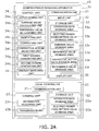
- FIG. 10 shows a settings screen for the identification conditions.
- This settings screen is displayed by pressing an Set Identification Conditions button (e.g., the symbol 706 in FIG. 7C ) provided in the lower part of the identification screen (i.e., FIG. 6 through FIG. 7C ), which shows the indoor units 12aa-12ad, 12ba-12bd, 12ca-12cd, ... identified according to the three viewpoints of excessive electric power consumption, long-time operation, and reduced comfort (all of which are discussed above).
- an Set Identification Conditions button e.g., the symbol 706 in FIG. 7C
- FIG. 6 through FIG. 7C shows the indoor units 12aa-12ad, 12ba-12bd, 12ca-12cd, ... identified according to the three viewpoints of excessive electric power consumption, long-time operation, and reduced comfort (all of which are discussed above).
- the settings screen is provided with a location (i.e., a symbol 1001) wherein the dates of the target interval is input, locations (i.e., symbols 1002a-1002c) wherein the target indoor unit of the indoor units 12aa-12ad, 12ba-12bd, 12ca-12cd, ... is selected, a location (i.e., a symbol 1003) for changing the determination criteria for excessive electric power consumption, a location (i.e., a symbol 1004) for changing the determination criteria for long-time operation, and a location (i.e., a symbol 1005) for changing the determination criteria for reduced comfort.
- a location i.e., a symbol 1001
- locations i.e., symbols 1002a-1002c
- the indoor units to be identified can be registered as a group and the conditions for identifying the problems can be set per group of the indoor units 12aa-12ad, 12ba-12bd, 12ca-12cd,
- the present invention is useful as an air conditioner managing apparatus that facilitates the work of specifying and checking the details of indoor units with problems in a property such as an office building wherein a plurality of indoor units are installed.
Landscapes
- Engineering & Computer Science (AREA)
- Chemical & Material Sciences (AREA)
- Combustion & Propulsion (AREA)
- Mechanical Engineering (AREA)
- General Engineering & Computer Science (AREA)
- Human Computer Interaction (AREA)
- Signal Processing (AREA)
- Physics & Mathematics (AREA)
- Fuzzy Systems (AREA)
- Mathematical Physics (AREA)
- Air Conditioning Control Device (AREA)
Applications Claiming Priority (3)
| Application Number | Priority Date | Filing Date | Title |
|---|---|---|---|
| JP2008014247 | 2008-01-24 | ||
| JP2008028926 | 2008-02-08 | ||
| PCT/JP2009/050706 WO2009093552A1 (fr) | 2008-01-24 | 2009-01-20 | Appareil de gestion de climatiseur |
Publications (2)
| Publication Number | Publication Date |
|---|---|
| EP2249093A1 true EP2249093A1 (fr) | 2010-11-10 |
| EP2249093A4 EP2249093A4 (fr) | 2014-12-24 |
Family
ID=40901060
Family Applications (1)
| Application Number | Title | Priority Date | Filing Date |
|---|---|---|---|
| EP09703872.3A Withdrawn EP2249093A4 (fr) | 2008-01-24 | 2009-01-20 | Appareil de gestion de climatiseur |
Country Status (8)
| Country | Link |
|---|---|
| US (1) | US20110057044A1 (fr) |
| EP (1) | EP2249093A4 (fr) |
| JP (1) | JP4396779B2 (fr) |
| KR (1) | KR20100113128A (fr) |
| CN (1) | CN101925785B (fr) |
| AU (1) | AU2009207168B2 (fr) |
| BR (1) | BRPI0906370A2 (fr) |
| WO (1) | WO2009093552A1 (fr) |
Cited By (1)
| Publication number | Priority date | Publication date | Assignee | Title |
|---|---|---|---|---|
| EP2913598A1 (fr) * | 2013-11-07 | 2015-09-02 | LG Electronics Inc. | Climatiseur et son procédé de fonctionnement |
Families Citing this family (16)
| Publication number | Priority date | Publication date | Assignee | Title |
|---|---|---|---|---|
| JP3861918B2 (ja) * | 2004-11-30 | 2006-12-27 | ダイキン工業株式会社 | 空気調和機 |
| US8239073B2 (en) * | 2008-04-17 | 2012-08-07 | Asoka Usa Corporation | Systems and methods for controlling energy consumption |
| JP5425582B2 (ja) * | 2009-09-30 | 2014-02-26 | 三洋電機株式会社 | 電気機器管理システム |
| JP5036793B2 (ja) * | 2009-11-27 | 2012-09-26 | 三菱電機株式会社 | 空気調和機の制御装置 |
| CN102713962B (zh) * | 2009-12-21 | 2015-09-02 | 松下电器产业株式会社 | 节能诊断系统 |
| KR101517084B1 (ko) * | 2012-11-12 | 2015-05-04 | 엘지전자 주식회사 | 공기조화기용 제어장치 |
| JP6033114B2 (ja) * | 2013-02-20 | 2016-11-30 | 三菱電機株式会社 | 遠隔操作表示装置 |
| JP6223432B2 (ja) * | 2013-04-08 | 2017-11-01 | 三菱電機株式会社 | 空調機管理装置及び空調機管理システム |
| JP6278718B2 (ja) * | 2014-01-27 | 2018-02-14 | 株式会社ガスター | 設定入力装置 |
| KR20160012795A (ko) * | 2014-07-25 | 2016-02-03 | 엘지전자 주식회사 | 공기조화시스템 |
| CN104534611B (zh) * | 2014-11-18 | 2017-12-19 | 珠海格力电器股份有限公司 | 空调器室内机的排序方法和装置、集中控制器和空调器 |
| CN107407490B (zh) * | 2015-04-07 | 2020-02-21 | 三菱电机株式会社 | 空调机的维护支持系统 |
| CN106918114B (zh) * | 2017-02-05 | 2020-04-03 | 广东美的暖通设备有限公司 | 多联机空调系统的通信方法及装置 |
| US11859844B2 (en) | 2018-06-13 | 2024-01-02 | Toshiba Carrier Corporation | Air conditioner management device, and air conditioner management screen generation method |
| JP6999510B2 (ja) * | 2018-06-28 | 2022-01-18 | 京セラ株式会社 | 電力変換装置 |
| USD1024091S1 (en) * | 2021-07-12 | 2024-04-23 | Forum Us, Inc. | Display screen or portion thereof with graphical user interface |
Family Cites Families (19)
| Publication number | Priority date | Publication date | Assignee | Title |
|---|---|---|---|---|
| JPH05157336A (ja) | 1991-12-10 | 1993-06-22 | Mitsubishi Heavy Ind Ltd | 空調料金算出システム |
| US5984502A (en) * | 1996-06-14 | 1999-11-16 | The Foxboro Company | Keypad annunciator graphical user interface |
| US6820026B1 (en) * | 1997-10-24 | 2004-11-16 | The Minster Machine Company | Console mounted vibration severity monitor |
| US5924486A (en) * | 1997-10-29 | 1999-07-20 | Tecom, Inc. | Environmental condition control and energy management system and method |
| CN1119577C (zh) * | 1997-12-25 | 2003-08-27 | 三菱电机株式会社 | 空调管理信息显示方法和空调管理装置 |
| EP0972996B1 (fr) * | 1997-12-25 | 2004-03-03 | Mitsubishi Denki Kabushiki Kaisha | Procede d'affichage des informations de commande de climatisation d'air et unite de commande de climatisation d'air |
| US6163740A (en) * | 1998-03-24 | 2000-12-19 | Beltracchi; Leo | Integrated iconic display for power plants by displaying plurality of process icons corresponding to all operating heat engines in one single computer screen |
| US6774786B1 (en) * | 2000-11-07 | 2004-08-10 | Fisher-Rosemount Systems, Inc. | Integrated alarm display in a process control network |
| JP3521843B2 (ja) * | 2000-04-20 | 2004-04-26 | ダイキン工業株式会社 | 空気調和装置の監視システム |
| JP3589171B2 (ja) * | 2000-10-05 | 2004-11-17 | 株式会社日立製作所 | 空気調和機のサービスシステム |
| US6813532B2 (en) * | 2001-03-01 | 2004-11-02 | Fisher-Rosemount Systems, Inc. | Creation and display of indices within a process plant |
| US7389204B2 (en) * | 2001-03-01 | 2008-06-17 | Fisher-Rosemount Systems, Inc. | Data presentation system for abnormal situation prevention in a process plant |
| JP2003042521A (ja) * | 2001-07-26 | 2003-02-13 | Hitachi Ltd | 空気調和装置 |
| US6978627B2 (en) * | 2002-01-31 | 2005-12-27 | Mitsubishi Denki Kabushiki Kaisha | Air conditioner control system, central remote controller, and facility controller |
| JP3742926B2 (ja) * | 2002-04-09 | 2006-02-08 | ダイキン工業株式会社 | 空調管理装置 |
| JP4549013B2 (ja) * | 2002-10-04 | 2010-09-22 | ダイキン工業株式会社 | 環境調整機器の監視装置、監視プログラムおよび監視方法 |
| KR100529907B1 (ko) * | 2003-06-19 | 2005-11-22 | 엘지전자 주식회사 | 에어컨의 중앙제어 시스템 및 그 동작방법 |
| KR100629345B1 (ko) * | 2005-02-24 | 2006-09-29 | 엘지전자 주식회사 | 멀티 공조 중앙제어시스템 |
| JP4151713B2 (ja) * | 2006-07-03 | 2008-09-17 | ダイキン工業株式会社 | 制御装置 |
-
2009
- 2009-01-14 JP JP2009006139A patent/JP4396779B2/ja active Active
- 2009-01-20 AU AU2009207168A patent/AU2009207168B2/en not_active Ceased
- 2009-01-20 BR BRPI0906370-6A patent/BRPI0906370A2/pt not_active IP Right Cessation
- 2009-01-20 EP EP09703872.3A patent/EP2249093A4/fr not_active Withdrawn
- 2009-01-20 CN CN2009801029517A patent/CN101925785B/zh not_active Expired - Fee Related
- 2009-01-20 US US12/863,280 patent/US20110057044A1/en not_active Abandoned
- 2009-01-20 KR KR1020107018262A patent/KR20100113128A/ko not_active Ceased
- 2009-01-20 WO PCT/JP2009/050706 patent/WO2009093552A1/fr not_active Ceased
Cited By (2)
| Publication number | Priority date | Publication date | Assignee | Title |
|---|---|---|---|---|
| EP2913598A1 (fr) * | 2013-11-07 | 2015-09-02 | LG Electronics Inc. | Climatiseur et son procédé de fonctionnement |
| US9696047B2 (en) | 2013-11-07 | 2017-07-04 | Lg Electronics Inc. | Air conditioner and method for operating an air conditioner |
Also Published As
| Publication number | Publication date |
|---|---|
| KR20100113128A (ko) | 2010-10-20 |
| AU2009207168B2 (en) | 2011-10-27 |
| US20110057044A1 (en) | 2011-03-10 |
| CN101925785B (zh) | 2013-05-15 |
| CN101925785A (zh) | 2010-12-22 |
| JP2009210253A (ja) | 2009-09-17 |
| JP4396779B2 (ja) | 2010-01-13 |
| BRPI0906370A2 (pt) | 2015-07-07 |
| EP2249093A4 (fr) | 2014-12-24 |
| AU2009207168A1 (en) | 2009-07-30 |
| WO2009093552A1 (fr) | 2009-07-30 |
Similar Documents
| Publication | Publication Date | Title |
|---|---|---|
| EP2249093A1 (fr) | Appareil de gestion de climatiseur | |
| EP1850440B1 (fr) | Systeme de gestion d'energie d'immeuble | |
| CN102105751B (zh) | 组管理装置及组管理系统 | |
| US8694174B2 (en) | Energy saving support device | |
| CN109308012B (zh) | 具有对建筑物能量和设备性能的多维分析的建筑物管理系统 | |
| US8949073B2 (en) | Diagnostic aid device | |
| EP4019856B1 (fr) | Dispositif de traitement d'informations | |
| EP1936292A2 (fr) | Système de climatisation et procédé de commande correspondant | |
| KR20080085733A (ko) | 리모트 성능 감시 장치 및 리모트 성능 감시 방법 | |
| CN102906771B (zh) | 节能诊断系统 | |
| EP2843785A1 (fr) | Dispositif et système de surveillance de puissance | |
| JP5517724B2 (ja) | 施設管理装置および施設管理方法 | |
| JP2009168296A (ja) | 空調機診断装置及び空調機診断方法 | |
| JP2017048962A (ja) | 空気調和システム、空気調和方法、及び制御装置 | |
| JP2015014823A (ja) | エネルギー使用量評価システム、エネルギー使用量評価演算装置及びプログラム | |
| US7280877B2 (en) | Facility control monitor method and facility control monitor apparatus | |
| JP2004118366A (ja) | 省エネルギー制御システム、省エネルギー制御方法、及び提示受付装置 | |
| KR101830859B1 (ko) | 가상 모델을 이용한 인터넷 데이터 센터의 에너지 진단 방법 | |
| JP2004138399A (ja) | 消費電力量算出装置及び消費電力量算出方法 | |
| Jensen et al. | Monitoring Building Systems for Schedule Compliance | |
| US20240291316A1 (en) | Energy resource control system, energy resource control method, and program | |
| EP2746688B1 (fr) | Dispositif de commande, procédé de commande, programme et support d'enregistrement |
Legal Events
| Date | Code | Title | Description |
|---|---|---|---|
| PUAI | Public reference made under article 153(3) epc to a published international application that has entered the european phase |
Free format text: ORIGINAL CODE: 0009012 |
|
| 17P | Request for examination filed |
Effective date: 20100817 |
|
| AK | Designated contracting states |
Kind code of ref document: A1 Designated state(s): AT BE BG CH CY CZ DE DK EE ES FI FR GB GR HR HU IE IS IT LI LT LU LV MC MK MT NL NO PL PT RO SE SI SK TR |
|
| AX | Request for extension of the european patent |
Extension state: AL BA RS |
|
| DAX | Request for extension of the european patent (deleted) | ||
| A4 | Supplementary search report drawn up and despatched |
Effective date: 20141124 |
|
| RIC1 | Information provided on ipc code assigned before grant |
Ipc: F24F 11/02 20060101AFI20141118BHEP |
|
| STAA | Information on the status of an ep patent application or granted ep patent |
Free format text: STATUS: EXAMINATION IS IN PROGRESS |
|
| 17Q | First examination report despatched |
Effective date: 20180808 |
|
| STAA | Information on the status of an ep patent application or granted ep patent |
Free format text: STATUS: THE APPLICATION HAS BEEN WITHDRAWN |
|
| 18W | Application withdrawn |
Effective date: 20181129 |