EP2249109A2 - Appareil de refroidissement, notamment appareil de refroidissement ménager doté d'une rainure pour eau de condensation - Google Patents
Appareil de refroidissement, notamment appareil de refroidissement ménager doté d'une rainure pour eau de condensation Download PDFInfo
- Publication number
- EP2249109A2 EP2249109A2 EP10160700A EP10160700A EP2249109A2 EP 2249109 A2 EP2249109 A2 EP 2249109A2 EP 10160700 A EP10160700 A EP 10160700A EP 10160700 A EP10160700 A EP 10160700A EP 2249109 A2 EP2249109 A2 EP 2249109A2
- Authority
- EP
- European Patent Office
- Prior art keywords
- rear wall
- evaporator
- condensation
- refrigerating appliance
- gutter
- Prior art date
- Legal status (The legal status is an assumption and is not a legal conclusion. Google has not performed a legal analysis and makes no representation as to the accuracy of the status listed.)
- Withdrawn
Links
- 238000001816 cooling Methods 0.000 claims abstract description 32
- 238000009833 condensation Methods 0.000 claims description 48
- 230000005494 condensation Effects 0.000 claims description 48
- 238000005057 refrigeration Methods 0.000 claims description 21
- XLYOFNOQVPJJNP-UHFFFAOYSA-N water Substances O XLYOFNOQVPJJNP-UHFFFAOYSA-N 0.000 claims description 10
- 230000008020 evaporation Effects 0.000 claims description 3
- 238000001704 evaporation Methods 0.000 claims description 3
- 238000007599 discharging Methods 0.000 claims 1
- 230000008014 freezing Effects 0.000 abstract description 7
- 238000007710 freezing Methods 0.000 abstract description 7
- 230000008901 benefit Effects 0.000 description 9
- 239000011521 glass Substances 0.000 description 6
- 241001274961 Rubus repens Species 0.000 description 5
- 239000006260 foam Substances 0.000 description 3
- 238000009434 installation Methods 0.000 description 3
- 238000009413 insulation Methods 0.000 description 3
- 235000013611 frozen food Nutrition 0.000 description 2
- 238000010257 thawing Methods 0.000 description 2
- 238000007664 blowing Methods 0.000 description 1
- 235000013399 edible fruits Nutrition 0.000 description 1
- 230000003028 elevating effect Effects 0.000 description 1
- 230000005484 gravity Effects 0.000 description 1
- 238000002347 injection Methods 0.000 description 1
- 239000007924 injection Substances 0.000 description 1
- JEIPFZHSYJVQDO-UHFFFAOYSA-N iron(III) oxide Inorganic materials O=[Fe]O[Fe]=O JEIPFZHSYJVQDO-UHFFFAOYSA-N 0.000 description 1
- 239000000463 material Substances 0.000 description 1
- 230000008018 melting Effects 0.000 description 1
- 238000002844 melting Methods 0.000 description 1
- 238000000034 method Methods 0.000 description 1
- 238000000465 moulding Methods 0.000 description 1
- 230000035515 penetration Effects 0.000 description 1
- 238000002791 soaking Methods 0.000 description 1
- 238000013517 stratification Methods 0.000 description 1
- 230000007704 transition Effects 0.000 description 1
- 235000013311 vegetables Nutrition 0.000 description 1
Images

Classifications
-
- F—MECHANICAL ENGINEERING; LIGHTING; HEATING; WEAPONS; BLASTING
- F25—REFRIGERATION OR COOLING; COMBINED HEATING AND REFRIGERATION SYSTEMS; HEAT PUMP SYSTEMS; MANUFACTURE OR STORAGE OF ICE; LIQUEFACTION SOLIDIFICATION OF GASES
- F25D—REFRIGERATORS; COLD ROOMS; ICE-BOXES; COOLING OR FREEZING APPARATUS NOT OTHERWISE PROVIDED FOR
- F25D21/00—Defrosting; Preventing frosting; Removing condensed or defrost water
- F25D21/14—Collecting or removing condensed and defrost water; Drip trays
-
- F—MECHANICAL ENGINEERING; LIGHTING; HEATING; WEAPONS; BLASTING
- F25—REFRIGERATION OR COOLING; COMBINED HEATING AND REFRIGERATION SYSTEMS; HEAT PUMP SYSTEMS; MANUFACTURE OR STORAGE OF ICE; LIQUEFACTION SOLIDIFICATION OF GASES
- F25D—REFRIGERATORS; COLD ROOMS; ICE-BOXES; COOLING OR FREEZING APPARATUS NOT OTHERWISE PROVIDED FOR
- F25D11/00—Self-contained movable devices, e.g. domestic refrigerators
- F25D11/02—Self-contained movable devices, e.g. domestic refrigerators with cooling compartments at different temperatures
- F25D11/022—Self-contained movable devices, e.g. domestic refrigerators with cooling compartments at different temperatures with two or more evaporators
-
- F—MECHANICAL ENGINEERING; LIGHTING; HEATING; WEAPONS; BLASTING
- F25—REFRIGERATION OR COOLING; COMBINED HEATING AND REFRIGERATION SYSTEMS; HEAT PUMP SYSTEMS; MANUFACTURE OR STORAGE OF ICE; LIQUEFACTION SOLIDIFICATION OF GASES
- F25D—REFRIGERATORS; COLD ROOMS; ICE-BOXES; COOLING OR FREEZING APPARATUS NOT OTHERWISE PROVIDED FOR
- F25D2321/00—Details or arrangements for defrosting; Preventing frosting; Removing condensed or defrost water, not provided for in other groups of this subclass
- F25D2321/14—Collecting condense or defrost water; Removing condense or defrost water
- F25D2321/144—Collecting condense or defrost water; Removing condense or defrost water characterised by the construction of drip water collection pans
- F25D2321/1441—Collecting condense or defrost water; Removing condense or defrost water characterised by the construction of drip water collection pans inside a refrigerator
-
- F—MECHANICAL ENGINEERING; LIGHTING; HEATING; WEAPONS; BLASTING
- F25—REFRIGERATION OR COOLING; COMBINED HEATING AND REFRIGERATION SYSTEMS; HEAT PUMP SYSTEMS; MANUFACTURE OR STORAGE OF ICE; LIQUEFACTION SOLIDIFICATION OF GASES
- F25D—REFRIGERATORS; COLD ROOMS; ICE-BOXES; COOLING OR FREEZING APPARATUS NOT OTHERWISE PROVIDED FOR
- F25D25/00—Charging, supporting, and discharging the articles to be cooled
- F25D25/02—Charging, supporting, and discharging the articles to be cooled by shelves
-
- F—MECHANICAL ENGINEERING; LIGHTING; HEATING; WEAPONS; BLASTING
- F25—REFRIGERATION OR COOLING; COMBINED HEATING AND REFRIGERATION SYSTEMS; HEAT PUMP SYSTEMS; MANUFACTURE OR STORAGE OF ICE; LIQUEFACTION SOLIDIFICATION OF GASES
- F25D—REFRIGERATORS; COLD ROOMS; ICE-BOXES; COOLING OR FREEZING APPARATUS NOT OTHERWISE PROVIDED FOR
- F25D2500/00—Problems to be solved
- F25D2500/02—Geometry problems
Definitions
- the invention relates to a refrigeration appliance, in particular domestic refrigeration appliance, with a body, which forms an inner container with a cold room and a freezer compartment, and a single-circuit refrigeration cycle, comprising a first evaporator associated with the freezer compartment and a second evaporator associated with the cold room, hidden behind a rear wall of the refrigerator compartment , wherein the rear wall of the inner container has a condensation gutter.
- the condensate collecting gutter has a gutter bed with a projecting approximately in the middle of its width section.
- the gutter bed is formed from a gutter wall and a gutter bottom, at the free edges of the gutter wall is arranged circumferentially.
- the channel bottom has a slope, which tapers on an introduced therein, arranged within the projecting portion drainage opening. The drain opening opens into a condensate drain pipe.
- the object of the invention is to provide a refrigeration device, in particular domestic refrigeration appliance, with a single-circuit refrigeration cycle, in which a refrigerator separate from the freezer compartment can be used more expediently for a user.
- a refrigerator in particular household refrigeration appliance, with a body that forms an inner container with a cold room and a freezer compartment, and a Ein Vietnamese tanninkte Vietnamese satu, having a freezer associated with the first evaporator and the refrigerator associated, hidden behind a rear wall of the refrigerator arranged second evaporator, wherein the Rear wall of the inner container having a condensation channel, wherein the condensation channel is arranged on the inside of the rear wall at a height immediately below the second evaporator.
- the evaporator tube or evaporator plate is located outside the refrigerator compartment, most often between the rear wall and the foam insulation, i. the evaporator is in contact with the outwardly oriented side of the rear wall.
- the inside of the refrigerator facing side of the rear wall is smooth-walled, usually formed without any projections. This is considered advantageous since no internal internals protrude into the cooling space and thus the useful volume available for the storage of refrigerated goods is not reduced.
- the smooth wall of the rear wall has been given preference in refrigerators with concealed evaporator.
- the necessary defrost channel was always provided at the bottom of the inner container.
- An upper edge of the condensation gutter can be arranged on the inside of the rear wall at a height in which a lower edge of the second, behind the rear wall hidden evaporator is located.
- indegefrierkombinations maricen the evaporator of the cooling space in the area is significantly smaller than the rear wall of the refrigerator. This is the case in particular with refrigerated freezing combination devices with a single-circuit cooling circuit. Only on the inner surface of the back wall, that of the hidden Evaporator is cooled, condensation occurs. On parts of the rear wall, which are not cooled by the evaporator, no condensation occurs.
- this uncooled part of the back wall becomes wet by the run-down of dew drops condensed in the area of the evaporator.
- the dew drops are collected immediately below the evaporator so that they can not reach the uncooled part of the rear wall.
- the dew drops are collected as before they can moisten the uncooled part of the back wall.
- This uncooled part of the back wall thus remains dry. Since this uncooled part of the back wall is dry, refrigerated goods can be stored in the cold room until they come into contact with the rear wall. Thus, the usable volume of the refrigerator is increased.
- the condensation gutter is therefore preferably arranged where, at the side of the rear wall pointing inwards towards the cooling space, a cooled section of the rear wall adjoins an uncooled section of the rear wall.
- This limit does not necessarily have to be exactly at the level of the lower edge of the evaporator.
- the cooled section at which humidity can condense, may deviate slightly from the height of the lower edge of the evaporator upwards or downwards.
- the second evaporator may be arranged, for example, in an upper third of the cooling space behind the inside of the rear wall, wherein the condensation gutter is mounted at the level two thirds of the total height of the cooling space on the inside of the rear wall.
- the evaporator for the refrigerator is made much smaller than single refrigerators without freezer or as inissergefrierkombinationations confusen with separate cooling circuits for the refrigerator and freezer.
- cooling freeze combination devices with a single-circuit refrigeration cycle have the result that a very large area of the rear wall is uncooled.
- An inventive "up-lay" the defrost channel is therefore particularly advantageous or effective inchengefrierkombinationations fürn with a single-circuit refrigeration cycle.
- the defrost channel can be formed in one piece with the rear wall having inner container.
- the condensation gutter may be structurally designed as a molding in the rear wall of the inner container of the refrigeration device. This has the advantage that no Installation of the condensation gutter is required and the number of parts is reduced, which is why the refrigeration device can be produced inexpensively.
- the defrost channel could be attached to the rear wall as a separate component, for example as a plastic injection molded part.
- the condensate drainage channel can have a drainage spigot, to which a drainage hose, for draining condensation water from the condensation gutter to an evaporation tray, is connected to a compressor of the refrigeration appliance.
- the condensation water collected by the condensation gutter is further fed to an evaporation tray on a compressor of the refrigeration appliance.
- This supply takes place via the drain hose.
- the compressor is below the bottom of the refrigerator outside the inner container of the refrigerator.
- the drain hose can be guided on the inside of the rear wall in the middle or in a corner of the bottom of the condensate drainage down.
- the drain hose can also be led out directly or just below the condensation gutter through the rear wall to the rear and, for example. Be performed in Isolierschaum outside the refrigerator down to the compressor. This has the advantage that no space for the drain hose is wasted in the refrigerator.
- the drain hose can thus be concealed behind the rear wall running out, outside the cooling chamber to a arranged below the inner container compressor.
- At least one upper shelf above the drainage channel and at least one lower shelf below the drainage channel can be arranged in the cold room, wherein the at least one lower shelf is formed to the rear wall contacting bearings of refrigerated goods without boundary strip. Since the condensation water condensing above the condensation gutter is collected at the level of the condensation gutter, the back wall below the condensation gutter remains dry. So refrigerated goods can be stored on the shelves located below the drainage gutters up to a back wall touching extent. In this case, no facilities are necessary to keep the refrigerated goods from the rear wall. A boundary strip or other stop can therefore be omitted according to the invention.
- Shelves and in particular glass plates which lie in front of the evaporator or in front of the drainage area of the condensate water must have a limit or a stop at the rear, ie on their side facing the rear wall, so that a user does not inadvertently bring refrigerated goods into contact with the rear wall. If this happens, there is a risk that the refrigerated goods will be moistened with condensation or even freeze on the cold rear wall. If the defrost channel is moved upwards according to the invention, the rear wall below the defrost channel is not wet and not cold. As a result, there is no danger to the user of soaking or freezing. For this reason, the rear stop or the boundary strip can be omitted on the shelves. This has the advantage that the shelves can be produced more cheaply. Another advantage is that the absence of the rear stop or the boundary strip increases the footprint on the shelf, which means increased customer benefit.
- one or more upper shelves for keeping the cold goods from the rear wall with a boundary strip and the one or more lower shelves to the rear wall touching bearings of refrigerated goods without boundary strip may be formed.
- boundary strips are still required to keep refrigerated goods from the rear wall can.
- the boundary strips can be omitted.
- the shelves of the lower two thirds of the total height of the cold room can do without boundary strips.
- the at least one lower shelf may have a greater depth than the at least one upper shelf. It's not just the boundary strips that fall away, it's the one is also no longer necessary that a certain distance between the rear, the rear wall facing edge of the shelf and the rear wall is maintained.
- the shelf can be used right up to the rear wall.
- the lower shelves ie the shelves located below the gutter, may have a greater depth than the upper shelves located above the gutter.
- the front ends of the upper and lower shelves facing the open side of the inner container or the door side of the refrigeration appliance can end in a common front plane. In this case results from the greater depth of the lower shelves, an increase in the total available footprint within the refrigerator.
- FIGS. 1 to 4 An exemplary embodiment of the invention is based on the FIGS. 1 to 4 described. From the detailed description of this specific embodiment, there are also other general features and advantages of the present invention.
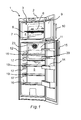
- An in Fig. 1 illustrated domestic refrigerator 1 has a body 2 with an inner container 3.
- the inner container 3 is in an overhead freezer compartment 4 and a divided below arranged cooling chamber 5.
- the freezer compartment 4 is generally used for freezing frozen food at about minus 18 degrees Celsius.
- the freezer compartment 4 is associated with a first evaporator 6, which is arranged hidden behind a freezer compartment rear wall 7.
- a grate 8 is used for the storage of frozen food on two levels.
- the freezer compartment 4 is accessible when the freezer compartment door 9 is open. To open, the freezer compartment door 9 has a first handle 10.
- the cooling space 5 is generally used for frost-free cooling of refrigerated goods, preferably at temperatures between plus 4 and plus 8 degrees Celsius. However, the cooling space 5 can also be designed as a zero-degree compartment, in particular for keeping fruit or vegetables fresh.
- the cooling space 5 has a rear wall 11, behind which a second evaporator 12 is hidden.
- the second evaporator 12 is connected in series with the first evaporator 6, ie it is a one-circuit refrigeration cycle which is connected to a common compressor 13 (FIG. Fig. 3 ) connected.
- the refrigerator 5 is accessible when the refrigerator door 14 is open. To open the refrigerator door 14 has a second handle 15.
- a defrost channel 20 is arranged on the inside of the rear wall 11.
- the defrosting channel 20 has an outlet connection 21, to which a drainage tube 22 (FIG. Fig. 3 ) connected.
- an optional fan 23 may be arranged, which provides for air circulation within the cooling chamber 5, but without blowing additional cold air from outside the inner container 3 into the cooling space 5.
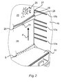
- Fig. 2 is shown as the invention according to the condensation channel 20 is arranged offset relative to a configuration S according to the prior art upwards.
- the defrost channel is arranged according to the embodiment S at the bottom 24 and at a bottom level of the inner container 3. Opposite this known position is the defrost channel 20 according to the invention, as indicated by the arrow P in Fig. 2 indicated, offset upwards.
- Behind a first wall portion 25 of the second evaporator 12 is hidden (and therefore in Fig. 2 not visible).
- atmospheric moisture in the form of dew drops 26 can condense.
- a second wall portion 26 is uncooled, as behind this wall portion 26 of the second evaporator 12 no longer extends.
- the area of the second wall section 26 is therefore dry, ie no dew drops are shown.
- the defrost channel 20 is located in the transition region between the first cooled wall section 25 and the second uncooled wall section 26.
- the defrost channel 20 has a gutter bed 27.
- the gutter bed 27 is formed from a gutter wall 28 and a gutter bottom 29, at the free edges of the gutter wall 28 is arranged circumferentially.
- the channel bottom 29 has a slope, which tapers on the introduced into it outlet pipe 21.
- the discharge nozzle 21 opens into the drain hose 22 (FIG. Fig. 3 ).
- Below the defrost channel 20 first receptacles 17a for lower shelves 19 and by way of example a second receptacle 17b for an upper shelf 18 are shown on the side walls 16 of the inner container 3 and the refrigerator compartment.
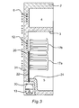
- Fig. 3 are shown in cross section a plurality of second receptacle 17b for upper shelves 18 and a plurality of first receptacles 17a for lower shelves 19.
- the defrost channel 20 is arranged.
- To the defrost channel 20 of the drain hose 22 is connected.
- the drain hose 22 is led to an evaporator shell 30, which is arranged on the upper side of the compressor 13.
- the drain hose 22 may be disposed extending within the foam insulation 31.
- Fig. 4 are bounded by the dashed corpus shown 2 two according to the invention upper shelves 18 and three according to the invention lower shelves 19, which are formed as glass plates 32 shown.
- Each glass plate 32 has an overmolded frame 33.
- Only the upper shelves 18 additionally have a boundary strip 34.
- the lower shelves 19 are formed without a boundary strip 34.
- the lower shelves 19 also have a greater depth T than the depth t of the upper shelves 18. The facing the open side of the inner container 3 and the door side of the refrigerator front ends 35 of the upper shelves 18 and lower shelves 19 ends in a common front plane 36.
Landscapes
- Engineering & Computer Science (AREA)
- Chemical & Material Sciences (AREA)
- Combustion & Propulsion (AREA)
- Physics & Mathematics (AREA)
- Mechanical Engineering (AREA)
- Thermal Sciences (AREA)
- General Engineering & Computer Science (AREA)
- Removal Of Water From Condensation And Defrosting (AREA)
- Devices That Are Associated With Refrigeration Equipment (AREA)
Applications Claiming Priority (1)
| Application Number | Priority Date | Filing Date | Title |
|---|---|---|---|
| DE102009002801A DE102009002801A1 (de) | 2009-05-04 | 2009-05-04 | Kältegerät, insbesondere Haushaltskältegerät mit einer Tauwasserrinne |
Publications (2)
| Publication Number | Publication Date |
|---|---|
| EP2249109A2 true EP2249109A2 (fr) | 2010-11-10 |
| EP2249109A3 EP2249109A3 (fr) | 2010-12-08 |
Family
ID=42635016
Family Applications (1)
| Application Number | Title | Priority Date | Filing Date |
|---|---|---|---|
| EP10160700A Withdrawn EP2249109A3 (fr) | 2009-05-04 | 2010-04-22 | Appareil de refroidissement, notamment appareil de refroidissement ménager doté d'une rainure pour eau de condensation |
Country Status (2)
| Country | Link |
|---|---|
| EP (1) | EP2249109A3 (fr) |
| DE (1) | DE102009002801A1 (fr) |
Cited By (2)
| Publication number | Priority date | Publication date | Assignee | Title |
|---|---|---|---|---|
| CN107830676A (zh) * | 2016-09-16 | 2018-03-23 | 东芝生活电器株式会社 | 冰箱 |
| CN117213155A (zh) * | 2023-09-27 | 2023-12-12 | 创维电器股份有限公司 | 一种冰箱冷冻室中的内胆防流水装置 |
Citations (4)
| Publication number | Priority date | Publication date | Assignee | Title |
|---|---|---|---|---|
| US2707871A (en) * | 1952-10-31 | 1955-05-10 | Philco Corp | Refrigeration apparatus |
| US3084519A (en) * | 1958-03-06 | 1963-04-09 | Whirlpool Co | Two temperature forced air refrigerator systems |
| DE19907124A1 (de) | 1999-02-19 | 2000-08-24 | Bsh Bosch Siemens Hausgeraete | Kältegerät |
| JP2006234220A (ja) | 2005-02-23 | 2006-09-07 | Matsushita Electric Ind Co Ltd | 冷蔵庫 |
Family Cites Families (11)
| Publication number | Priority date | Publication date | Assignee | Title |
|---|---|---|---|---|
| US2167442A (en) * | 1936-06-18 | 1939-07-25 | Westinghouse Electric & Mfg Co | Refrigeration apparatus |
| GB773927A (en) * | 1954-08-19 | 1957-05-01 | Gen Electric | Improvements relating to refrigerators |
| JPS4723743U (fr) * | 1971-03-18 | 1972-11-16 | ||
| JPS5346602Y2 (fr) * | 1976-07-06 | 1978-11-08 | ||
| JPS576942Y2 (fr) * | 1977-04-30 | 1982-02-09 | ||
| GB8512339D0 (en) * | 1985-05-15 | 1985-06-19 | Hotpoint Ltd | Refrigerators |
| DE19652032B4 (de) * | 1996-12-13 | 2010-10-07 | BSH Bosch und Siemens Hausgeräte GmbH | Kühlgerät |
| DE19724267A1 (de) * | 1997-06-09 | 1998-12-10 | Bosch Siemens Hausgeraete | Kühlgerät |
| AT500939B1 (de) * | 2005-06-08 | 2006-11-15 | Aht Cooling Systems Gmbh | Kühlgerät |
| DE202006013228U1 (de) * | 2006-08-29 | 2006-10-26 | BSH Bosch und Siemens Hausgeräte GmbH | Haushaltsgerät mit Wasserablauf |
| KR20080029498A (ko) * | 2006-09-29 | 2008-04-03 | 삼성전자주식회사 | 냉장고 |
-
2009
- 2009-05-04 DE DE102009002801A patent/DE102009002801A1/de not_active Ceased
-
2010
- 2010-04-22 EP EP10160700A patent/EP2249109A3/fr not_active Withdrawn
Patent Citations (4)
| Publication number | Priority date | Publication date | Assignee | Title |
|---|---|---|---|---|
| US2707871A (en) * | 1952-10-31 | 1955-05-10 | Philco Corp | Refrigeration apparatus |
| US3084519A (en) * | 1958-03-06 | 1963-04-09 | Whirlpool Co | Two temperature forced air refrigerator systems |
| DE19907124A1 (de) | 1999-02-19 | 2000-08-24 | Bsh Bosch Siemens Hausgeraete | Kältegerät |
| JP2006234220A (ja) | 2005-02-23 | 2006-09-07 | Matsushita Electric Ind Co Ltd | 冷蔵庫 |
Cited By (2)
| Publication number | Priority date | Publication date | Assignee | Title |
|---|---|---|---|---|
| CN107830676A (zh) * | 2016-09-16 | 2018-03-23 | 东芝生活电器株式会社 | 冰箱 |
| CN117213155A (zh) * | 2023-09-27 | 2023-12-12 | 创维电器股份有限公司 | 一种冰箱冷冻室中的内胆防流水装置 |
Also Published As
| Publication number | Publication date |
|---|---|
| DE102009002801A1 (de) | 2010-11-11 |
| EP2249109A3 (fr) | 2010-12-08 |
Similar Documents
| Publication | Publication Date | Title |
|---|---|---|
| EP2694894B1 (fr) | Dispositif combiné de refrigeration | |
| EP2104818A1 (fr) | Condenseur pour appareil frigorifique | |
| WO2006130886A1 (fr) | Appareil de refrigeration | |
| EP2697578B1 (fr) | Appareil frigorifique comportant un bac d'évaporation | |
| EP3359891A1 (fr) | Appareil de froid pourvu d'un siphon situé dans l'évacuation de condensat | |
| DE102017216206A1 (de) | Haushaltskältegerät mit mechanisch betätigbarer Sprüheinheit zur Zugabe von Fluidnebel in einen Frischhaltebehälter | |
| EP2522937A2 (fr) | Dispositif de vaporisation pour un appareil frigorifique encastrable ainsi qu'appareil frigorifique encastrable et procédé d'encastrement d'un appareil frigorifique encastrable | |
| DE102017213972A1 (de) | Kältegerät mit Verdunstungsschale | |
| EP2249109A2 (fr) | Appareil de refroidissement, notamment appareil de refroidissement ménager doté d'une rainure pour eau de condensation | |
| DE19652032B4 (de) | Kühlgerät | |
| EP2372277A2 (fr) | Appareil de refroidissement doté d'un évaporateur d'eau de décongélation | |
| WO2011020801A1 (fr) | Appareil de réfrigération comportant un canal d'évacuation de l'eau de dégivrage et un siphon | |
| EP1845322B1 (fr) | Appareil de réfrigération et/ou de refroidissement | |
| DE102018116181A1 (de) | Kühl- und/oder Gefriergerät | |
| EP2646765A2 (fr) | Appareil frigorifique comportant une coque d'évaporation | |
| DE102011087810A1 (de) | Kältegerät mit einer Verdunstungsschale | |
| WO2012072473A2 (fr) | Appareil frigorifique comportant une coque d'évaporation | |
| EP2083233A2 (fr) | Appareil frigorifique encastrable | |
| WO2016074893A1 (fr) | Appareil de réfrigération sans givre | |
| DE2915297C2 (de) | Kühlmöbel, insbesondere Mehrtemperaturen-Kühlschrank | |
| EP2458307B1 (fr) | Appareil de refroidissement doté d'un dispositif goutte à goutte de collecte et d'un dispositif de déviation | |
| DE102018122904A1 (de) | Gefriertruhe, insbesondere für Eiscreme-Produkte | |
| DE10063691B4 (de) | Kühlgerät | |
| DE102009026665A1 (de) | Kältegerät | |
| EP2682693B1 (fr) | Appareil de réfrigération avec distribution de glace ou d'eau |
Legal Events
| Date | Code | Title | Description |
|---|---|---|---|
| PUAI | Public reference made under article 153(3) epc to a published international application that has entered the european phase |
Free format text: ORIGINAL CODE: 0009012 |
|
| PUAL | Search report despatched |
Free format text: ORIGINAL CODE: 0009013 |
|
| AK | Designated contracting states |
Kind code of ref document: A2 Designated state(s): AT BE BG CH CY CZ DE DK EE ES FI FR GB GR HR HU IE IS IT LI LT LU LV MC MK MT NL NO PL PT RO SE SI SK SM TR |
|
| AX | Request for extension of the european patent |
Extension state: AL BA ME RS |
|
| AK | Designated contracting states |
Kind code of ref document: A3 Designated state(s): AT BE BG CH CY CZ DE DK EE ES FI FR GB GR HR HU IE IS IT LI LT LU LV MC MK MT NL NO PL PT RO SE SI SK SM TR |
|
| AX | Request for extension of the european patent |
Extension state: AL BA ME RS |
|
| 17P | Request for examination filed |
Effective date: 20110608 |
|
| RAP1 | Party data changed (applicant data changed or rights of an application transferred) |
Owner name: BSH HAUSGERAETE GMBH |
|
| 17Q | First examination report despatched |
Effective date: 20170529 |
|
| STAA | Information on the status of an ep patent application or granted ep patent |
Free format text: STATUS: THE APPLICATION IS DEEMED TO BE WITHDRAWN |
|
| 18D | Application deemed to be withdrawn |
Effective date: 20171010 |