EP2249110A2 - Système de distribution personnalisé de vrac ou de produits secs - Google Patents
Système de distribution personnalisé de vrac ou de produits secs Download PDFInfo
- Publication number
- EP2249110A2 EP2249110A2 EP10159707A EP10159707A EP2249110A2 EP 2249110 A2 EP2249110 A2 EP 2249110A2 EP 10159707 A EP10159707 A EP 10159707A EP 10159707 A EP10159707 A EP 10159707A EP 2249110 A2 EP2249110 A2 EP 2249110A2
- Authority
- EP
- European Patent Office
- Prior art keywords
- container
- module
- appliance
- user
- interior
- Prior art date
- Legal status (The legal status is an assumption and is not a legal conclusion. Google has not performed a legal analysis and makes no representation as to the accuracy of the status listed.)
- Withdrawn
Links
- 238000003860 storage Methods 0.000 claims description 44
- 230000007246 mechanism Effects 0.000 claims description 30
- 239000002274 desiccant Substances 0.000 claims description 10
- 239000000203 mixture Substances 0.000 claims description 7
- 150000003839 salts Chemical class 0.000 claims description 7
- 238000000034 method Methods 0.000 description 9
- 235000013305 food Nutrition 0.000 description 8
- 239000007789 gas Substances 0.000 description 5
- 239000000463 material Substances 0.000 description 4
- 238000005192 partition Methods 0.000 description 4
- 125000006850 spacer group Chemical group 0.000 description 3
- FAPWRFPIFSIZLT-UHFFFAOYSA-M Sodium chloride Chemical compound [Na+].[Cl-] FAPWRFPIFSIZLT-UHFFFAOYSA-M 0.000 description 2
- 239000002253 acid Substances 0.000 description 2
- 230000008901 benefit Effects 0.000 description 2
- 235000013339 cereals Nutrition 0.000 description 2
- 238000006243 chemical reaction Methods 0.000 description 2
- 239000012530 fluid Substances 0.000 description 2
- 238000009920 food preservation Methods 0.000 description 2
- 238000009434 installation Methods 0.000 description 2
- 230000013011 mating Effects 0.000 description 2
- 230000001105 regulatory effect Effects 0.000 description 2
- 244000105624 Arachis hypogaea Species 0.000 description 1
- UFHFLCQGNIYNRP-UHFFFAOYSA-N Hydrogen Chemical compound [H][H] UFHFLCQGNIYNRP-UHFFFAOYSA-N 0.000 description 1
- 241000533293 Sesbania emerus Species 0.000 description 1
- 240000006365 Vitis vinifera Species 0.000 description 1
- 235000014787 Vitis vinifera Nutrition 0.000 description 1
- 230000004913 activation Effects 0.000 description 1
- 229910052783 alkali metal Inorganic materials 0.000 description 1
- -1 alkali metal salts Chemical class 0.000 description 1
- 239000002585 base Substances 0.000 description 1
- 235000013361 beverage Nutrition 0.000 description 1
- 239000013590 bulk material Substances 0.000 description 1
- 230000015556 catabolic process Effects 0.000 description 1
- 230000001413 cellular effect Effects 0.000 description 1
- 238000004140 cleaning Methods 0.000 description 1
- 150000001875 compounds Chemical class 0.000 description 1
- 238000010276 construction Methods 0.000 description 1
- 230000003247 decreasing effect Effects 0.000 description 1
- 238000006731 degradation reaction Methods 0.000 description 1
- 238000005516 engineering process Methods 0.000 description 1
- 230000002255 enzymatic effect Effects 0.000 description 1
- 235000013312 flour Nutrition 0.000 description 1
- 239000008187 granular material Substances 0.000 description 1
- 239000001257 hydrogen Substances 0.000 description 1
- 229910052739 hydrogen Inorganic materials 0.000 description 1
- 239000007788 liquid Substances 0.000 description 1
- 238000004519 manufacturing process Methods 0.000 description 1
- 238000005259 measurement Methods 0.000 description 1
- 229910052751 metal Inorganic materials 0.000 description 1
- 239000002184 metal Substances 0.000 description 1
- 230000000813 microbial effect Effects 0.000 description 1
- 230000003278 mimic effect Effects 0.000 description 1
- 238000003032 molecular docking Methods 0.000 description 1
- 230000006855 networking Effects 0.000 description 1
- 235000016709 nutrition Nutrition 0.000 description 1
- 239000002245 particle Substances 0.000 description 1
- 235000020232 peanut Nutrition 0.000 description 1
- 238000004321 preservation Methods 0.000 description 1
- 230000008569 process Effects 0.000 description 1
- 238000005057 refrigeration Methods 0.000 description 1
- 230000001953 sensory effect Effects 0.000 description 1
- 239000011780 sodium chloride Substances 0.000 description 1
- 239000002699 waste material Substances 0.000 description 1
Images









Classifications
-
- F—MECHANICAL ENGINEERING; LIGHTING; HEATING; WEAPONS; BLASTING
- F25—REFRIGERATION OR COOLING; COMBINED HEATING AND REFRIGERATION SYSTEMS; HEAT PUMP SYSTEMS; MANUFACTURE OR STORAGE OF ICE; LIQUEFACTION SOLIDIFICATION OF GASES
- F25D—REFRIGERATORS; COLD ROOMS; ICE-BOXES; COOLING OR FREEZING APPARATUS NOT OTHERWISE PROVIDED FOR
- F25D23/00—General constructional features
- F25D23/02—Doors; Covers
- F25D23/04—Doors; Covers with special compartments, e.g. butter conditioners
-
- F—MECHANICAL ENGINEERING; LIGHTING; HEATING; WEAPONS; BLASTING
- F25—REFRIGERATION OR COOLING; COMBINED HEATING AND REFRIGERATION SYSTEMS; HEAT PUMP SYSTEMS; MANUFACTURE OR STORAGE OF ICE; LIQUEFACTION SOLIDIFICATION OF GASES
- F25D—REFRIGERATORS; COLD ROOMS; ICE-BOXES; COOLING OR FREEZING APPARATUS NOT OTHERWISE PROVIDED FOR
- F25D23/00—General constructional features
- F25D23/12—Arrangements of compartments additional to cooling compartments; Combinations of refrigerators with other equipment, e.g. stove
Definitions
- Refrigerators are available in many styles, with the most common styles including both a refrigerator compartment and a freezer compartment, which may be side-by-side or one on top of the other. Controls regulate the temperature in each compartment, but otherwise there is very little control over the precise temperature, humidity, pressure, gas composition, and other variables in each respective compartment. Thus, within each refrigerator or freezer compartment, the conditions are substantially uniform throughout the compartment.
- refrigerator compartments generally do a good job of preserving food items for a short period of time, different foods, beverages, and non-food items require different conditions for maximum preservation. Storage techniques of food in the compartment can also affect the shelf life of the food item. Generally, food preservation in the refrigerator or freezer compartments is limited to a shorter time than is desired by many consumers. Perishability is typically caused by microbial degradation, enzymatic activities, and chemical reactions which may result in changes in safety, sensory, and nutritional quality of the food.
- One object of the present invention is to provide an appliance with a rear wall section, a first side wall section, a second side wall section, at least one door, a top, and a bottom that define an interior of the appliance.
- a refrigerator section is typically included within the appliance interior.
- the refrigerator section may have the same or a smaller volume than the interior of the entire appliance.
- the door(s) have an exterior surface and an interior surface having a door liner and a cavity.
- a module removably engaged with the appliance.
- a resealable comestible dry goods container having a defined interior volume, an exterior, and a bottom portion wherein the container is removably engaged within the module.
- Another object of the present invention is to provide a portable dry goods storage and dispensing unit capable of engaging the interior surface of a door of a refrigeration appliance.
- a module capable of being engaged and disengaged with an interior surface of a refrigerator door.
- the module further includes at least one, and more typically a plurality of, resealable comestible dry goods container(s) having a defined interior volume, an exterior, and a bottom portion.
- the container(s) are removably engaged with the module and include a metering and dispensing mechanism positioned proximate the bottom portion of the container such that the mechanism controls content output amount of dry goods from the container's interior volume.
- the module is also typically capable of maintaining a storage effecting condition (humidity, temperature, pressure, gas composition, and combinations thereof), within the interior of the module and/or the individual containers.
- a storage effecting condition humidity, temperature, pressure, gas composition, and combinations thereof
- the temperature of the interior volume of the container is independently controlled and the humidity of the container is independently maintained by a humidity controller (i.e., a desiccant, a salt packet, or a heater).
- the container(s) typically further include a resealable, typically substantially air tight or air tight, removable lid on each of the containers.
- the desiccant may be removably engaged to the container interior facing surface of the lid.
- a further object of the present invention includes a method for a user to store and dispense comestible dry goods.
- the method generally involves providing an appliance with a refrigerator section and an appliance door that provides access to the refrigerator section and having an exterior surface and an interior surface, the interior surface having a door liner.
- the door typically includes a module engaging connector for providing at least electrical power to a module.
- the module that is removably engaged with the door's interior and sized to fit within the door liner is also utilized in the method.
- the module also typically contains a utility connector that matingly and operatively connects with the module engaging connector of the appliance to supply at least electrical power to the module.
- a resealable comestible dry goods container (or more than one container) that is removably engaged within the module and typically seated within a bottom portion of the module.
- the container has an interior volume, an exterior, and a bottom portion.
- the module, or more typically the container further includes a metering and/or dispensing mechanism positioned proximate the bottom portion of the container and typically below the dry goods output aperture in the bottom of the container.
- the mechanism controls content output amount of dry goods from the container's interior volume.
- the user engages the module with the interior of the door, which typically includes operably connecting the module engaging connector to the module utility connector thereby providing at least electrical power from the refrigerator and to the module.
- the resealable comestible dry goods container(s) are engaged with the module either before or after the container is filled with a dry good by inserting at least a portion of the container into a receiving port or section of the module. Thereafter, a desired content output amount of dry goods from within the container interior volume can be metered and dispensed out of the container by the user.
- the amount dispensed is typically a user defined output amount.
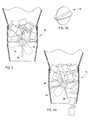
- Fig. 1 is an elevational front view of an appliance with a refrigerator section
- Fig. 1A is an elevational front view of the refrigerator section including a module and dry or bulk goods storage and dispensing containers mounted in the module;
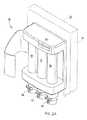
- Fig. 2 is an upper right perspective view of the module and the dry or bulk goods storage and dispensing containers;
- Fig. 2A is an upper right perspective view of the module further illustrating the dry or bulk goods storage and dispensing containers;
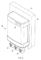
- Fig. 3 is an elevational front view of the module and the dry or bulk goods storage and dispensing containers;
- Fig. 4 is an elevational side view of the module and the dry or bulk goods storage and dispensing containers
- Fig. 5 is an elevational side view of the module just prior to engaging the refrigerator door
- Fig. 5A is an elevational side view of module engaging the refrigerator door
- Fig. 5B is an elevational side view of module engaged with the refrigerator door
- Fig. 5C is an elevational side view of a refrigerator door port area after removal of the module
- Fig. 6 is an exploded perspective view of the dry or bulk goods storage and dispensing container
- Fig. 6A is an exploded perspective view of the dry or bulk goods storage and dispensing container
- Fig. 6B is a perspective view of the dry or bulk goods storage and dispensing container
- Fig. 7 is an upper right perspective view of the module engaging a countertop stand illustrating the portability of the module
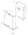
- Fig. 7A is a rear perspective view of the module prior to engaging the countertop stand illustrating the portability of the module
- Fig. 7B is a rear perspective view of the module engaging a countertop stand illustrating the portability of the module
- Fig. 8 is a front right perspective view of the module prior to engaging a mounted wall bracket illustrating the portability of the module;
- Fig. 9 is an elevational front view of a first embodiment of a rotatable dispensing member with large spacing
- Fig. 9A is an elevational front view of a first embodiment of the rotatable dispensing member, with large spacing, rotating to illustrate dispensing of the dry or bulk goods;
- Fig. 9B is a perspective view of a first embodiment of the rotatable dispensing member with large spacing
- Fig. 10 is an elevational front view of a first embodiment of a rotatable dispensing member with medium spacing
- Fig. 10A is an elevational front view of a first embodiment of the rotatable dispensing member, with medium spacing, rotating to illustrate dispensing of the dry or bulk goods;
- Fig. 10B is a perspective view of a first embodiment of the rotatable dispensing member with medium spacing
- Fig. 11 is an elevational front view of a first embodiment of a rotatable dispensing member with small spacing
- Fig. 11A is an elevational front view of a first embodiment of the rotatable dispensing member, with small spacing, rotating to illustrate dispensing of the dry or bulk goods;
- Fig. 11B is a perspective view of a first embodiment of the rotatable dispensing member with small spacing
- Fig. 12 is a perspective view of a second embodiment of the dry or bulk goods storage and dispensing container
- Fig. 13 is an exploded view of a second embodiment of the dry or bulk goods storage and dispensing container
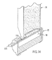
- Fig. 14 is a perspective cross-sectional view of a second embodiment of the metering and dispensing member of the dry or bulk goods storage and dispensing container;
- Fig. 14A is a cross-sectional view of a second embodiment of the metering and dispensing member of the dry or bulk goods storage and dispensing container;
- Fig. 14B is a perspective cross-sectional view of a second embodiment of the metering and dispensing member of the dry or bulk goods storage and dispensing container illustrating the metering device in motion;
- Fig. 14C is a cross-sectional view of a second embodiment of the metering and dispensing member of the dry or bulk goods storage and dispensing container illustrating the metering device in motion;
- Fig. 14D is a perspective cross-sectional view of a second embodiment of the metering and dispensing member of the dry or bulk goods storage and dispensing container illustrating dispensing of the dry or bulk goods;
- Fig. 15 is a perspective view of a third embodiment of a dry or bulk goods storage and dispensing container
- Fig. 15A is an exploded view of a third embodiment of the dry or bulk goods storage and dispensing container
- Fig. 15B is a perspective view of a third embodiment of a dry or bulk goods storage and dispensing container
- Fig. 16 is an exploded view of a third embodiment of the dry or bulk goods storage and dispensing container
- Fig. 17 is a perspective view of a container partition for the dry or bulk goods storage and dispensing container
- Fig. 17A is a perspective view of a container partition for the dry or bulk goods storage and dispensing container
- Fig. 17B is a perspective view of a container partition for the dry or bulk goods storage and dispensing container
- Fig. 18 is a perspective view of a third embodiment of the dry or bulk goods storage and dispensing container
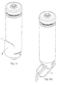
- Fig. 19 is a perspective view of the dry or bulk goods container with a conveyor slide in a closed position
- Fig. 19A is a perspective view of a dry or bulk goods container with a conveyor slide in an opened position
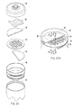
- Fig. 20 is an exploded perspective view of a recess within the container lid, housing a desiccant or a salt;
- Fig. 20A is a perspective view of a lid with apertures, illustrating air flow between the recess and the container.
- the terms "upper,” “lower,” “right,” “left,” “rear,” “front,” “vertical,” “horizontal,” and derivatives thereof shall relate to the appliance as orientated in Fig. 1 .
- the invention may assume various alternative orientations, except where expressly specified to the contrary.
- the specific devices and processes illustrated in the attached drawings, and described in the following specification are simply exemplary embodiments of the inventive concepts defined in the appended claims. Hence, specific dimensions and other physical characteristics relating to the embodiments disclosed herein are not to be considered as limiting, unless the claims expressly state otherwise.
- the reference number 10 ( Figs. 1-1A ) generally designates an appliance with a rear wall section 12, a first side wall section 14, a second side wall section 16, a top 18, a bottom 20, and at least one door 22 providing access to the refrigerator section 24 where the rear wall section, the first side wall section, the second side wall section, the top and bottom, and the door define an appliance interior 26.
- the refrigerator section within the appliance interior may have the same or a smaller volume than the overall interior of the appliance, i.e., the appliance may be solely a refrigerator or be an appliance having both a refrigerator section and another section, such as a freezer section.
- the door(s) of the appliance have an exterior surface 28 and an interior surface 30 typically having a door liner 32.
- the liner is typically formed with a cavity or pocket 34 for receiving one or more modules with the same or different features.
- modules that, for example, produce a modified atmosphere to preserve food such as those disclosed in commonly owned U.S. Patent Application Serial Nos. 12/346,682 and 12/343,690 , may also or alternatively be coupled with the appliance.
- the illustrated appliance 10 is shown with the door 22 hingably attached to the appliance.
- the door covers at least a portion of the refrigerator section 24 that lies within the appliance interior 26, and as shown, the door is in an opened position.
- the door has an exterior surface 28 and an interior surface 30, with the interior surface exposed in the opened position.
- the door liner 32 at least partially covers, but more typically covers all or substantially all of the interior surface 30 of the door 22.
- An interface between the modules and the appliance door such as interconnecting tabs and grooves or a magnetic engagement, allows for quick and easy installation docking without the use of tools.
- Differently sized modules may be accommodated through the use of spacer systems that engage the interior of the door and shorten the lateral distance that the module must traverse to engage the spacer.
- the spacer when used, would mimic a smaller mounting distance/door pocket or cavity and similarly have an interface such as a tabular on groove mating or magnetic engagement.
- the modular construction and interchangeability of modules minimizes manufacturing costs and allows the module to be original equipment or after-market components retro-fit into appliances, after the initial purchase and installation of the appliance in a consumer's home.
- This interchangeability provides flexibility and improved food preservation and storage for the consumer, improved choice of modules with opportunity to upgrade or replace without replacing the whole refrigerator based upon lifestyle or life stage changes, and allows the consumer to take advantage of new technology improvements and new features as new modules are designed and developed.
- a dry goods dispensing and metering module 36 ( Figs. 1-8 , 12 ) according to one embodiment of the present invention is removably engaged with the door 22 and sized to fit within the door liner 32, typically within the cavity or pocket 34 of the door liner, however connectivity to an exterior surface of the door may also be accomplished.
- Engagement of the module 36 with the door 22 occurs by engaging the module with the refrigerator door.
- the module can be engaged to the door 22 in any convenient manner, such as by interlocking tabs, a small support shelf or floor, or other mechanical means or a magnetic arrangement (for example, a magnet on each side of the module for attraction to magnets of opposite polarity on each side of the door liner) may also be used.
- the door typically includes a module engaging connector 38 for providing the electrical power to the module.
- the door module engaging connector 38 may also provide one or more utilities such as fluids and chilled air to the module. Conceivably a separate utility connector could be used such that power is serviced differently from other utility or utilities.
- a separate utility connector could be used such that power is serviced differently from other utility or utilities.
- the dry goods module of the present invention typically only electrical power is applied to the dry goods module 36.
- the dry goods module of the present invention typically receives at least electrical power from the appliance 10.
- the door 22 may provide the ability to engage a plurality of modules to the appliance.
- Figs. 5-5C generally illustrate the engagement of a module 36 to a door 22.
- a spring biased connection port cover 50 is hingably engaged with the liner 32 or door 22 such that when a module 36 is not engaged with the door, the connector with the port area 52, typically a female connector in the door 22 for engaging the module, is protected against debris from the food or other items stored in the appliance 10 that would potentially block or hamper operable connection of the module 36.
- a Reed switch may be provided in the door liner for activation by a magnet imbedded in the side wall of the module so as to complete an electric circuit when the module docks into the door pocket. Contact pads on the liner and on the module that complete the electrical circuit when the module is mounted in the door liner may also be employed.
- the module 36 of the present invention may optionally be engaged with a countertop stand 60 and/or a wall bracket 62.
- the countertop stand 60 and wall bracket 62 would typically also include a connector (typically a female connector) within a port area protected by a spring-biased port cover.
- the module typically draws electrical power and optionally other utilities.
- the stand When a countertop stand 60 is utilized, as shown in Figs. 7-7B , the stand typically includes a base and an upright section that substantially mimics a pocket or cavity of a refrigerator or other appliance door liner.
- the module 36 typically engages the sides of the countertop stand 60 for retaining the module in place via interlocking tabular members, and/or a pin type arrangement or other mechanical means or magnetically as described above.
- the countertop stand 60 or wall bracket 62 includes a spring biased hinged cover that inwardly pivots when the module's connection plug (typically male-type) is inserted therein. The cover, as discussed before, prevents debris and other materials from contacting the module engaging connector of the countertop stand and/or wall bracket.
- the module 36 typically contains a generally L-shaped connection plug 64 (male-type) that is inserted into the cavity containing the module engaging connector thereby moving the cover inward about the hinge.
- the module is engaged with the module engaging connector when the module is tilted into position and dropped into engagement with the countertop stand 60, wall bracket 62, or door 22.
- This configuration is generally shown in Figs. 7-7B .
- the countertop stand itself may draw electrical power from a separate outlet or directly from the appliance via an umbilical utility cord 76 type attachment.
- the utility cord from the appliance could also conceivably supply cold air or liquid or other utilities to the module.
- At least one, but more typically a plurality of resealable, comestible dry goods container(s) 70 having a defined interior volume, an exterior, and a bottom portion are removably engaged with the module 36 for ease of filling and cleaning (the container(s) are typically dishwasher safe) and sized to fit into a standard dishwasher.
- the container also typically includes a metering and dispensing mechanism 72 positioned proximate the bottom portion of the container, such that the mechanism controls the output amount of the dry goods within the container's interior volume when the dispensing mechanism 72 is actuated by a user of the module. Dispensement may occur at an interior or exterior region of the appliance, regardless of the module position.
- an access door or recess may be provided, similar to that of an ice maker output area.
- an opening in the door or appliance located adjacent the dispensing mechanism 72 allows the dry goods to fall similar to that of ice in an ice maker, via gravitational force.
- a substantially vertically aligned channel or conduit may be connected to the dispensing mechanism 72, thereby allowing for transport of the falling dry goods to the access door or recess area.
- the mechanism's metering device may be adjustable such that it can, based upon user input or selection, dispense a variety of amounts of a given dry good accurately.
- individual containers may utilize a specified dispensing mechanism suitable for a given dry good to be dispensed. For example, if dry cereal or other high volume bulk material is stored, the typical serving may be one cup, the container may be metered to only dispense in one cup intervals or a predetermined non-adjustable amount. In this instance a gearing mechanism would not be necessary.
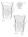
- the metering mechanism 72 may include a rotatable dispensing member 78 positioned below an aperture in the bottom of the container ( Figs. 9-11B ).
- the rotatable member typically includes a plurality of equal sections and is operably connected to a user operated handle via a gear mechanism.
- the gear mechanism operates to adjust the extent of the rotation of the rotating member and thereby the amount of dry goods being dispensed.
- the sizes of the section of the rotatable member are typically provided in three general sizes.
- the rotatable member with the largest spacing ( Figs. 9-9B ) allows for dispensing of high volume bulk goods such as cereals, and whole coffee beans.
- the medium sized sections ( Fig.
- the metering and dispensing mechanism 72 is located proximate the bottom portion of the container, bag, or compartment.
- a user may input a desired output amount of the comestible dry goods to be dispensed manually (using for example, a rotatable dial) or by interacting with a user-interface display 40.
- the container may include a handle 44 on the exterior of the container, which in turn rotates a shaft 46 that is connected to the handle at a first end of the shaft.
- the shaft 46 is coupled to a gear system proximate a second end of the shaft.
- the gear system in one embodiment converts the rotational motion of the shaft to translational motion of a slide actuator.
- the slide actuator typically has one or more apertures sized to dispense the dry goods.
- Rotation of the handle 44, shaft 46, and gear system generates movement of the slide actuator to a position that corresponds to expelling of a user-desired input amount.
- a specific distance of a turn of the handle may correspond to a particular output amount.
- a half rotation turn of the handle may correspond to metering and dispensing of one cup of a particular dry good.
- the type of comestible dry goods stored will vary and the same ratio of turn to output amount will not be uniform. Therefore, established ratios will be provided to a user, thereby allowing for easy conversions of output amounts.
- the gear system converts the rotational motion of the shaft into increased or decreased rotation of the rotating member of specified section volume (see discussion above), from which amounts may be determined.
- the metering and dispensing may also be accomplished by including at least one receptacle 112 within a rotatable cylinder 110 spaced proximate the bottom portion of the container ( Figs. 12-14D ).
- the receptacle 112 has a manipulatable size that corresponds to a user-desired output amount of the container interior volume.
- a user may retract or expand the volume of each receptacle 112 in order to hold a desired amount of comestible dry goods.
- the dispensing mechanism is capable of expelling the contents of each receptacle upon command from the user, via manual means or by employing the user-interface display.
- a tumbler elongated cylinder
- a cavity 118 (typically a trough with a triangular cross-section) is coupled to the handle 114 and a moveable (sliding) volume regulator 116 with a top and downward projection section that is spaced within the cavity of the tumbler and sized approximately the same as the cross-section of the cavity, travels back and forth as the amount to be dispensed is adjusted by the user to create a dispensing volume that is adjustable based upon the gearing to be employed.
- the handle 114 is turned to the loading position with the cavity facing upward toward the dry goods in the upper portion of the container and the dry goods fall into the cavity. Once filled, the cavity 118 rotates when the handle is actuated to a downward facing position, which results in the dispensing of the dry goods.
- the containers include vertically elongated partitions 102 that form receptacles within each container. These volumes of the receptacles are manipulatable, thereby adjusting the storage capability of the receptacles.
- a slider 104 may move in a vertical fashion in order to accomplish the volume retractability. The movement of the slider may be actuated by a manual lever, a manual dial on the exterior of the container, or any other convenient means.
- the contents of each receptacle are dispensed by the turning of a crank or handle, or by interacting with the user-interface display.
- metering and dispensing may be accomplished by including a scale that weighs the output amount.
- the module with data-stored densities of commonly-stored comestible dry goods, is capable of converting the weight of dispensed goods to volume. Dispensement occurs until the user-desired output amount is met.
- the container or the module of the present invention typically further include a dry goods conveyor slide 74 that is rotatable between a position that dispenses dry goods in a direction away from the module for ease of use by the user ( Figs. 19-19A ).
- the conveyor slide may fold or retract into a storage position (in addition to or instead of rotating) to allow for easy appliance door closure when the module is engaged with the interior surface of the door.
- the containers of the storage and dispensing module are also typically resealable such that they form an air-tight or substantially air-tight seal on the container for the comestible dry goods.
- the container(s) typically have an interior volume, an exterior and a bottom portion.
- the bottom portion of the containers may include a dispensing mechanism or a dispensing and metering mechanism as discussed above.
- the dispensing or dispensing and metering systems may be incorporated into the bottom portion of the dry goods module itself.
- the containers operably engage with the module (typically by being slotted or placed within one or more sections of the bottom portion of the module).
- the sections may have a predefined area with generally U-shaped, upwardly facing channels for mating with the bottom edge rim of the containers, which are typically clear plastic.
- the containers are not tightly engaged with the module, but rather some small amount of movement or play (generally lateral movement) is desirable. It is presently believed that slight movement of the containers when the door of the appliance engaged with the module is opened and closed provides a deterrent or at least partially prevents caking of dry goods within the container.
- the storage and dispensing module may optionally maintain a storage effecting condition within the interior of the container (i.e., humidity, temperature, pressure, gas composition, and combinations thereof), which may be different from that of the atmospheric condition immediately surrounding the module.
- a storage effecting condition within the interior of the container (i.e., humidity, temperature, pressure, gas composition, and combinations thereof), which may be different from that of the atmospheric condition immediately surrounding the module.
- the module may maintain one more temperature, humidity, pressure, and/or gas levels.
- the module may be capable of maintaining the container at a plurality of various temperatures, above, below, or at about ambient temperature.
- a desiccant 82, a salt or heater may be used to regulate humidity, which may be monitored by a sensor and the output of the sensor may be displayed or communicated to the user.
- a salt may be any compound formed when the acid hydrogen of an acid is partly or wholly replaced by a metal or a metallic radical, including, but not limited to, alkali metal salts such as sodium chloride.
- a desiccant disk that adjustably regulates humidity may be removably engaged with the container to treat humidity within the container ( Figs. 20-20A ). For example, the desiccant may be placed within a recess in the container lid. Just under the container lid 90, the desiccant 82 rests on a aperture disk 94. The aperture disk has an upper cover 92 and a lower cover 96 that may both be adjusted to uncover a portion of the aperture disk.
- the entire humidity regulating recess rests within a jacket 98 that connects the container lid 90 to the container body 84.
- a single desiccant could regulate a plurality of containers if operably connected with the interior of more than one container to treat the humidity within the containers.
- the module is capable of operably associating with a plurality of containers. Additionally, the module may be illuminated independently of the refrigerator section to enhance visibility of the containers engaged with the module, especially when the refrigerator door is open and the module engaged to the interior of the refrigerator door.
- the user-interface or a switch allows the user to illuminate the module, as needed.
- the module of the portable unit may also include a sensor that is capable of indicating a user predetermined level of container contents, so that prior to complete depletion of the dry goods material within the container, a user is warned of the low level. Like the storage effecting condition, this information could conceivably be delivered via computer network to a user defined electronic mail box/account or a mobile device such as a cellular telephone or an electronically kept grocery list via, for example, a computer networking device.
- the present invention further provides a method for a user to store and dispense comestible dry goods.
- a user may engage a dry goods module according to an embodiment of the present invention with an appliance, typically a refrigerator door interior, a wall mounted bracket, or a countertop stand as described earlier.
- an appliance typically a refrigerator door interior, a wall mounted bracket, or a countertop stand as described earlier.
- the module is engaged with connectors on both the module and the wall bracket, countertop stand or the appliance such that at least electrical power is supplied to the module.
- the removable container(s) of the modules Prior to or after the module is engaged with the appliance or other device, the removable container(s) of the modules are filled with one or more dry goods (each container having a different dry good or a mix of dry goods) and engaged with the bottom portion of the module.
- the user can dispense the material.
- the user may set the amount of material to be dispensed through a user-interface, which may be a computer controlled interface or a manually controlled interface.
- the user may dispense the dry goods, which may be done manually by the user moving an actuator such as a handle operably connected to the dispensing mechanism or automatically using an electrical motor to actuate the dispensing mechanism.
- the method of storing the dry goods may be enhanced by maintaining a storage effecting condition within the interior of the container.
- This step involves regulating humidity, temperature, pressure, and/or gas composition, either singularly or in combination. It should be noted that the disclosed method steps may be performed in various orders, not limited to the order presented here unless specifically so indicated.
Landscapes
- Engineering & Computer Science (AREA)
- Chemical & Material Sciences (AREA)
- Combustion & Propulsion (AREA)
- Physics & Mathematics (AREA)
- Mechanical Engineering (AREA)
- Thermal Sciences (AREA)
- General Engineering & Computer Science (AREA)
- Devices That Are Associated With Refrigeration Equipment (AREA)
Applications Claiming Priority (1)
| Application Number | Priority Date | Filing Date | Title |
|---|---|---|---|
| US12/434,121 US20100276442A1 (en) | 2009-05-01 | 2009-05-01 | Personalized dry or bulk dispensing system |
Publications (2)
| Publication Number | Publication Date |
|---|---|
| EP2249110A2 true EP2249110A2 (fr) | 2010-11-10 |
| EP2249110A3 EP2249110A3 (fr) | 2015-02-25 |
Family
ID=42424365
Family Applications (1)
| Application Number | Title | Priority Date | Filing Date |
|---|---|---|---|
| EP10159707.8A Withdrawn EP2249110A3 (fr) | 2009-05-01 | 2010-04-13 | Système de distribution personnalisé de vrac ou de produits secs |
Country Status (2)
| Country | Link |
|---|---|
| US (1) | US20100276442A1 (fr) |
| EP (1) | EP2249110A3 (fr) |
Cited By (1)
| Publication number | Priority date | Publication date | Assignee | Title |
|---|---|---|---|---|
| EP4040090A1 (fr) * | 2021-02-08 | 2022-08-10 | Whirlpool Corporation | Réfrigérateur domestique doté d'un système de fabrication de glaçons |
Families Citing this family (23)
| Publication number | Priority date | Publication date | Assignee | Title |
|---|---|---|---|---|
| US8299656B2 (en) | 2008-03-12 | 2012-10-30 | Whirlpool Corporation | Feature module connection system |
| US8166872B2 (en) | 2008-03-12 | 2012-05-01 | Whirlpool Corporation | Modified atmosphere for food preservation |
| DE102011077489A1 (de) * | 2011-06-14 | 2012-12-20 | Sb Limotive Company Ltd. | Trocknungseinrichtung sowie Batteriesystem und Kraftfahrzeug mit dieser Trocknungseinrichtung |
| US9212839B2 (en) * | 2012-02-16 | 2015-12-15 | Erliene Launetta McCoy | Portable insulated ice dispenser |
| US9414568B2 (en) * | 2012-02-28 | 2016-08-16 | Doskocil Manufacturing Company, Inc | Manual portion control feeder |
| US8938980B2 (en) * | 2012-08-24 | 2015-01-27 | Whirlpool Corporation | Integrated ice maker pump |
| AU2014233096A1 (en) * | 2013-03-15 | 2015-09-24 | Step Ahead Innovations, Inc. | Aquatic environment additive dosing apparatuses and systems, and methods and software therefor |
| US11284748B2 (en) | 2014-09-09 | 2022-03-29 | Chowbotics | Enhanced automated food making apparatus |
| US10813503B2 (en) | 2014-09-09 | 2020-10-27 | Casabots Inc. | Automated food making apparatus |
| US11918150B2 (en) * | 2014-09-09 | 2024-03-05 | DoorDash, Inc. | Enhanced automated food making apparatus |
| WO2017015409A1 (fr) * | 2015-07-20 | 2017-01-26 | Pahmet Llc | Système compartimenté de stockage et de traitement pour articles périssables et non périssables |
| WO2017155829A2 (fr) * | 2016-03-06 | 2017-09-14 | Kathirasen Kathirgugan | Appareil automatisé de fabrication d'aliments |
| CN106705553B (zh) * | 2017-01-24 | 2019-06-07 | 青岛海高设计制造有限公司 | 谷物分配装置及具有该谷物分配装置的冰箱 |
| CN106642904B (zh) * | 2017-01-24 | 2023-04-18 | 青岛海高设计制造有限公司 | 冷藏冷冻装置 |
| CN106766612B (zh) * | 2017-01-24 | 2019-10-08 | 青岛海高设计制造有限公司 | 谷物分配装置及具有该谷物分配装置的冰箱 |
| CN108548362B (zh) * | 2018-03-26 | 2021-05-25 | 重庆海尔制冷电器有限公司 | 具有干燥区的冰箱及干燥区的除湿方法 |
| CN113669994B (zh) * | 2020-05-15 | 2024-10-18 | 青岛海尔电冰箱有限公司 | 冰箱门体 |
| CN212778175U (zh) * | 2020-05-15 | 2021-03-23 | 青岛海尔特种电冰箱有限公司 | 冰箱门体 |
| CN113669995B (zh) * | 2020-05-15 | 2025-02-07 | 青岛海尔电冰箱有限公司 | 冰箱门体 |
| CN111829279B (zh) * | 2020-06-12 | 2022-03-04 | 合肥美的电冰箱有限公司 | 容纳器、分储装置和冰箱 |
| CN113148464B (zh) * | 2021-02-09 | 2023-03-28 | 运易通科技有限公司 | 一种具有循环再生硅胶干燥剂结构的海运集装箱 |
| KR20230043615A (ko) * | 2021-09-24 | 2023-03-31 | 삼성전자주식회사 | 냉장고 |
| US20230292703A1 (en) * | 2022-03-21 | 2023-09-21 | Doskocil Manufacturing Company, Inc. | Feeder |
Family Cites Families (40)
| Publication number | Priority date | Publication date | Assignee | Title |
|---|---|---|---|---|
| US3178061A (en) * | 1963-12-18 | 1965-04-13 | Joseph J Giacalone | Refrigerator door canteen |
| US4759193A (en) * | 1987-09-08 | 1988-07-26 | Dehring Paul E | Horizontal refrigerator |
| US5219103A (en) * | 1991-12-30 | 1993-06-15 | Whirlpool Corporation | Refrigerator coffee dispenser having an auger and a pick-up wheel |
| US5440894A (en) * | 1993-05-05 | 1995-08-15 | Hussmann Corporation | Strategic modular commercial refrigeration |
| KR960010668B1 (ko) * | 1993-11-06 | 1996-08-07 | 엘지전자 주식회사 | 냉장고 |
| US5603417A (en) * | 1995-03-13 | 1997-02-18 | Blair; Norman T. | Bag sealing apparatus |
| US5588558A (en) * | 1995-03-17 | 1996-12-31 | Van-Bar Enterprises, Inc. | Liquid beverage dispenser |
| US6085542A (en) * | 1998-06-30 | 2000-07-11 | Maytag Corporation | Refrigerator door storage system |
| US6148624A (en) * | 1998-12-28 | 2000-11-21 | Whirlpool Corporation | Ice making system for a refrigerator |
| US6612116B2 (en) * | 1999-02-26 | 2003-09-02 | Maytag Corporation | Thermoelectric temperature controlled refrigerator food storage compartment |
| US6751525B1 (en) * | 2000-06-08 | 2004-06-15 | Beverage Works, Inc. | Beverage distribution and dispensing system and method |
| MXPA04000422A (es) * | 2001-07-16 | 2004-11-22 | Maytag Corp | Compartimiento enfriador de puerta francesa para refrigeradores. |
| US7703639B2 (en) * | 2002-06-25 | 2010-04-27 | Tamir Levy | Granular product dispensing system |
| US6782710B2 (en) * | 2002-07-16 | 2004-08-31 | Maytag Corporation | Kid's zone compartment assembly for a refrigerator |
| BR0204561B1 (pt) * | 2002-10-18 | 2011-10-18 | arranjo de acessórios para porta de refrigerador e porta-latas para refrigerador. | |
| US7404298B2 (en) * | 2003-03-10 | 2008-07-29 | Lg Electronics Inc. | Refrigerator |
| US7334853B2 (en) * | 2003-03-19 | 2008-02-26 | General Electric Company | Refrigerator door beverage storage module |
| US7000407B2 (en) * | 2003-05-22 | 2006-02-21 | General Electric Company | Methods and apparatus for controlling refrigerators |
| US8007847B2 (en) * | 2004-01-13 | 2011-08-30 | Eytan Biderman | Feeding formula appliance |
| USD511179S1 (en) * | 2004-02-25 | 2005-11-01 | Maytag Corporation | Door bin for a refrigerator |
| US6991134B2 (en) * | 2004-05-07 | 2006-01-31 | Bailey Robert L | Device to store, sift and measure flour |
| WO2005124247A2 (fr) * | 2004-06-08 | 2005-12-29 | Michael Krieger | Glaciere extensible |
| US7188479B2 (en) * | 2004-10-26 | 2007-03-13 | Whirlpool Corporation | Ice and water dispenser on refrigerator compartment door |
| US20090277199A1 (en) * | 2004-12-08 | 2009-11-12 | Teknoloji Dizayn Studyo Produksiyon Ve Reklamcilik Anonim Sirketi | Refrigerator capable of stock monitoring by providing ideal storage conditions |
| EP1848304A1 (fr) * | 2004-12-22 | 2007-10-31 | Daewoo Electronics Corporation | Rangement multi-fonctionnel pour services de puericulture |
| US7775065B2 (en) * | 2005-01-14 | 2010-08-17 | General Electric Company | Methods and apparatus for operating a refrigerator |
| RU2388976C2 (ru) * | 2005-03-02 | 2010-05-10 | Эл Джи Электроникс Инк. | Холодильник |
| USD522542S1 (en) * | 2005-05-10 | 2006-06-06 | Whirlpool Corporation | Storage bin |
| DE102006063088B3 (de) * | 2005-09-23 | 2023-07-06 | Lg Electronics Inc. | Kühlschranktür |
| KR20070043446A (ko) * | 2005-10-21 | 2007-04-25 | 삼성전자주식회사 | 냉장고 |
| US7469553B2 (en) * | 2005-11-21 | 2008-12-30 | Whirlpool Corporation | Tilt-out ice bin for a refrigerator |
| DE102005057142A1 (de) * | 2005-11-30 | 2007-06-06 | BSH Bosch und Siemens Hausgeräte GmbH | Kältegerät mit modularem Steuer- und Verdampferaufbau |
| USD527749S1 (en) * | 2006-01-11 | 2006-09-05 | Maytag Corporation | Can storage and dispensing container for a refrigerator |
| US8608263B2 (en) * | 2006-01-11 | 2013-12-17 | Whirlpool Corporation | Beverage container storage and dispensing compartment for a refrigerator |
| WO2008037405A1 (fr) * | 2006-09-29 | 2008-04-03 | Aktiebolaget Electrolux | Nouvel appareil de cuisine |
| US7762102B2 (en) * | 2006-12-28 | 2010-07-27 | General Electric Company | Soft freeze assembly for a freezer storage compartment |
| US8453476B2 (en) * | 2009-05-21 | 2013-06-04 | Whirlpool Corporation | Refrigerator module mounting system |
| US7980088B2 (en) * | 2007-01-04 | 2011-07-19 | Whirlpool Corporation | Removable adapter providing a wireless service to removable consumer electronic device |
| US7736179B2 (en) * | 2007-09-12 | 2010-06-15 | Whirlpool Corporation | Refrigerator with plug-in power supply |
| US8769981B2 (en) * | 2009-12-22 | 2014-07-08 | Lg Electronics Inc. | Refrigerator with ice maker and ice level sensor |
-
2009
- 2009-05-01 US US12/434,121 patent/US20100276442A1/en not_active Abandoned
-
2010
- 2010-04-13 EP EP10159707.8A patent/EP2249110A3/fr not_active Withdrawn
Cited By (2)
| Publication number | Priority date | Publication date | Assignee | Title |
|---|---|---|---|---|
| EP4040090A1 (fr) * | 2021-02-08 | 2022-08-10 | Whirlpool Corporation | Réfrigérateur domestique doté d'un système de fabrication de glaçons |
| US11703264B2 (en) | 2021-02-08 | 2023-07-18 | Whirlpool Corporation | Ice making system for a refrigerator appliance |
Also Published As
| Publication number | Publication date |
|---|---|
| US20100276442A1 (en) | 2010-11-04 |
| EP2249110A3 (fr) | 2015-02-25 |
Similar Documents
| Publication | Publication Date | Title |
|---|---|---|
| US20100276442A1 (en) | Personalized dry or bulk dispensing system | |
| US12253301B2 (en) | Refrigerator with quick fill dispenser incorporating removable fluid storage receptacle | |
| RU2448024C2 (ru) | Дозатор охлажденных покрытий для десертов | |
| US8240158B2 (en) | Modified atmosphere for food preservation | |
| US8353177B2 (en) | Apparatus and method for dispensing ice from a bottom mount refrigerator | |
| US6145705A (en) | Dry condiment dispensing system | |
| US9518772B2 (en) | Domestic refrigerator including an ice dispenser | |
| EP4011251B1 (fr) | Ensemble de distribution de boisson modulaire pour appareil de réfrigération | |
| US20130126556A1 (en) | Topping Dispenser | |
| KR20200062308A (ko) | 탠덤 저장통 및/또는 분리가능한 디스펜서 리세스부를 가진 냉장고 제빙 시스템 | |
| US20240401873A1 (en) | Refrigerator with quick fill dispenser incorporating removable fluid storage receptacle and combined inlet/outlet | |
| EP4177552B1 (fr) | Appareil réfrigérateur et distributeur de glace définissant une sortie de liquide | |
| US10852046B2 (en) | Refrigerator with door-mounted fluid dispenser | |
| US20060113324A1 (en) | Multi-product dispenser and method of using same | |
| US10928121B1 (en) | Smart refrigerator | |
| US12546525B2 (en) | Dispenser assembly for stand-alone ice making appliance | |
| US4009593A (en) | Refrigrated salad and salad dressing dispensing apparatus | |
| US11530868B2 (en) | Herb storage assembly for a refrigerator appliance | |
| US20250237423A1 (en) | Dispenser assembly for stand-alone ice making appliance | |
| CN111829279B (zh) | 容纳器、分储装置和冰箱 | |
| EP2138785A2 (fr) | Atmosphère modifiée pour conservation d'aliments | |
| CN111981744A (zh) | 一种储粮结构及冰箱 | |
| JP2002034458A (ja) | コーヒー豆ブレンド装置 |
Legal Events
| Date | Code | Title | Description |
|---|---|---|---|
| PUAI | Public reference made under article 153(3) epc to a published international application that has entered the european phase |
Free format text: ORIGINAL CODE: 0009012 |
|
| AK | Designated contracting states |
Kind code of ref document: A2 Designated state(s): AT BE BG CH CY CZ DE DK EE ES FI FR GB GR HR HU IE IS IT LI LT LU LV MC MK MT NL NO PL PT RO SE SI SK SM TR |
|
| PUAL | Search report despatched |
Free format text: ORIGINAL CODE: 0009013 |
|
| AK | Designated contracting states |
Kind code of ref document: A3 Designated state(s): AT BE BG CH CY CZ DE DK EE ES FI FR GB GR HR HU IE IS IT LI LT LU LV MC MK MT NL NO PL PT RO SE SI SK SM TR |
|
| RIC1 | Information provided on ipc code assigned before grant |
Ipc: F25D 23/12 20060101ALI20150116BHEP Ipc: F25D 23/04 20060101AFI20150116BHEP Ipc: A47G 19/34 20060101ALN20150116BHEP |
|
| STAA | Information on the status of an ep patent application or granted ep patent |
Free format text: STATUS: THE APPLICATION IS DEEMED TO BE WITHDRAWN |
|
| 18D | Application deemed to be withdrawn |
Effective date: 20150826 |