EP2249115A2 - Échangeur de chaleur pour douche - Google Patents
Échangeur de chaleur pour douche Download PDFInfo
- Publication number
- EP2249115A2 EP2249115A2 EP10161866A EP10161866A EP2249115A2 EP 2249115 A2 EP2249115 A2 EP 2249115A2 EP 10161866 A EP10161866 A EP 10161866A EP 10161866 A EP10161866 A EP 10161866A EP 2249115 A2 EP2249115 A2 EP 2249115A2
- Authority
- EP
- European Patent Office
- Prior art keywords
- water
- slab
- heat exchanging
- cambered
- shower
- Prior art date
- Legal status (The legal status is an assumption and is not a legal conclusion. Google has not performed a legal analysis and makes no representation as to the accuracy of the status listed.)
- Withdrawn
Links
- 238000003287 bathing Methods 0.000 title claims abstract description 27
- XLYOFNOQVPJJNP-UHFFFAOYSA-N water Substances O XLYOFNOQVPJJNP-UHFFFAOYSA-N 0.000 claims abstract description 135
- 238000007789 sealing Methods 0.000 claims abstract description 14
- 229910002065 alloy metal Inorganic materials 0.000 claims abstract description 6
- 239000007769 metal material Substances 0.000 claims abstract description 6
- 238000003466 welding Methods 0.000 claims description 4
- 229910000838 Al alloy Inorganic materials 0.000 claims description 2
- 239000000463 material Substances 0.000 claims description 2
- 150000002736 metal compounds Chemical class 0.000 claims description 2
- 229910052755 nonmetal Inorganic materials 0.000 claims description 2
- RYGMFSIKBFXOCR-UHFFFAOYSA-N Copper Chemical compound [Cu] RYGMFSIKBFXOCR-UHFFFAOYSA-N 0.000 claims 1
- 229910000881 Cu alloy Inorganic materials 0.000 claims 1
- 229910052802 copper Inorganic materials 0.000 claims 1
- 239000010949 copper Substances 0.000 claims 1
- 229910052751 metal Inorganic materials 0.000 description 33
- 239000002184 metal Substances 0.000 description 33
- 230000000694 effects Effects 0.000 description 17
- 239000008399 tap water Substances 0.000 description 15
- 235000020679 tap water Nutrition 0.000 description 15
- 238000004519 manufacturing process Methods 0.000 description 14
- 238000000034 method Methods 0.000 description 10
- 238000004021 metal welding Methods 0.000 description 8
- 230000005611 electricity Effects 0.000 description 5
- 230000003247 decreasing effect Effects 0.000 description 4
- 230000002035 prolonged effect Effects 0.000 description 4
- OKTJSMMVPCPJKN-UHFFFAOYSA-N Carbon Chemical compound [C] OKTJSMMVPCPJKN-UHFFFAOYSA-N 0.000 description 3
- 229910052799 carbon Inorganic materials 0.000 description 3
- 238000005553 drilling Methods 0.000 description 3
- 238000009434 installation Methods 0.000 description 3
- 239000007921 spray Substances 0.000 description 3
- 230000037396 body weight Effects 0.000 description 2
- 230000007423 decrease Effects 0.000 description 2
- 230000007613 environmental effect Effects 0.000 description 2
- 238000000465 moulding Methods 0.000 description 2
- 229920000049 Carbon (fiber) Polymers 0.000 description 1
- 238000005452 bending Methods 0.000 description 1
- 239000004917 carbon fiber Substances 0.000 description 1
- 238000005520 cutting process Methods 0.000 description 1
- 238000004512 die casting Methods 0.000 description 1
- 230000002349 favourable effect Effects 0.000 description 1
- 238000010438 heat treatment Methods 0.000 description 1
- 238000002347 injection Methods 0.000 description 1
- 239000007924 injection Substances 0.000 description 1
- 230000007774 longterm Effects 0.000 description 1
- VNWKTOKETHGBQD-UHFFFAOYSA-N methane Chemical compound C VNWKTOKETHGBQD-UHFFFAOYSA-N 0.000 description 1
- 230000001737 promoting effect Effects 0.000 description 1
- 239000002351 wastewater Substances 0.000 description 1
Images


Classifications
-
- F—MECHANICAL ENGINEERING; LIGHTING; HEATING; WEAPONS; BLASTING
- F28—HEAT EXCHANGE IN GENERAL
- F28F—DETAILS OF HEAT-EXCHANGE AND HEAT-TRANSFER APPARATUS, OF GENERAL APPLICATION
- F28F3/00—Plate-like or laminated elements; Assemblies of plate-like or laminated elements
- F28F3/12—Elements constructed in the shape of a hollow panel, e.g. with channels
-
- F—MECHANICAL ENGINEERING; LIGHTING; HEATING; WEAPONS; BLASTING
- F28—HEAT EXCHANGE IN GENERAL
- F28D—HEAT-EXCHANGE APPARATUS, NOT PROVIDED FOR IN ANOTHER SUBCLASS, IN WHICH THE HEAT-EXCHANGE MEDIA DO NOT COME INTO DIRECT CONTACT
- F28D21/00—Heat-exchange apparatus not covered by any of the groups F28D1/00 - F28D20/00
- F28D21/0001—Recuperative heat exchangers
- F28D21/0012—Recuperative heat exchangers the heat being recuperated from waste water or from condensates
-
- F—MECHANICAL ENGINEERING; LIGHTING; HEATING; WEAPONS; BLASTING
- F28—HEAT EXCHANGE IN GENERAL
- F28D—HEAT-EXCHANGE APPARATUS, NOT PROVIDED FOR IN ANOTHER SUBCLASS, IN WHICH THE HEAT-EXCHANGE MEDIA DO NOT COME INTO DIRECT CONTACT
- F28D9/00—Heat-exchange apparatus having stationary plate-like or laminated conduit assemblies for both heat-exchange media, the media being in contact with different sides of a conduit wall
- F28D9/0081—Heat-exchange apparatus having stationary plate-like or laminated conduit assemblies for both heat-exchange media, the media being in contact with different sides of a conduit wall the conduits for one heat-exchange medium being formed by a single plate-like element ; the conduits for one heat-exchange medium being integrated in one single plate-like element
-
- F—MECHANICAL ENGINEERING; LIGHTING; HEATING; WEAPONS; BLASTING
- F28—HEAT EXCHANGE IN GENERAL
- F28D—HEAT-EXCHANGE APPARATUS, NOT PROVIDED FOR IN ANOTHER SUBCLASS, IN WHICH THE HEAT-EXCHANGE MEDIA DO NOT COME INTO DIRECT CONTACT
- F28D1/00—Heat-exchange apparatus having stationary conduit assemblies for one heat-exchange medium only, the media being in contact with different sides of the conduit wall, in which the other heat-exchange medium is a large body of fluid, e.g. domestic or motor car radiators
- F28D1/02—Heat-exchange apparatus having stationary conduit assemblies for one heat-exchange medium only, the media being in contact with different sides of the conduit wall, in which the other heat-exchange medium is a large body of fluid, e.g. domestic or motor car radiators with heat-exchange conduits immersed in the body of fluid
- F28D1/0246—Heat-exchange apparatus having stationary conduit assemblies for one heat-exchange medium only, the media being in contact with different sides of the conduit wall, in which the other heat-exchange medium is a large body of fluid, e.g. domestic or motor car radiators with heat-exchange conduits immersed in the body of fluid heat-exchange elements having several adjacent conduits forming a whole, e.g. blocks
-
- F—MECHANICAL ENGINEERING; LIGHTING; HEATING; WEAPONS; BLASTING
- F28—HEAT EXCHANGE IN GENERAL
- F28F—DETAILS OF HEAT-EXCHANGE AND HEAT-TRANSFER APPARATUS, OF GENERAL APPLICATION
- F28F2250/00—Arrangements for modifying the flow of the heat exchange media, e.g. flow guiding means; Particular flow patterns
- F28F2250/04—Communication passages between channels
-
- Y—GENERAL TAGGING OF NEW TECHNOLOGICAL DEVELOPMENTS; GENERAL TAGGING OF CROSS-SECTIONAL TECHNOLOGIES SPANNING OVER SEVERAL SECTIONS OF THE IPC; TECHNICAL SUBJECTS COVERED BY FORMER USPC CROSS-REFERENCE ART COLLECTIONS [XRACs] AND DIGESTS
- Y02—TECHNOLOGIES OR APPLICATIONS FOR MITIGATION OR ADAPTATION AGAINST CLIMATE CHANGE
- Y02B—CLIMATE CHANGE MITIGATION TECHNOLOGIES RELATED TO BUILDINGS, e.g. HOUSING, HOUSE APPLIANCES OR RELATED END-USER APPLICATIONS
- Y02B30/00—Energy efficient heating, ventilation or air conditioning [HVAC]
- Y02B30/56—Heat recovery units
Definitions
- the present invention relates to an energy saving heat exchanger for a bathing shower, the heat exchanger having a simple structure that significantly decreases manufacturing time and costs and provides enhanced energy saving efficiency so as to make the heat exchanger more affordable and attractive to consumers.
- the invention not only provides increased popularity but also offers environmental protection due to increased energy saving and reduced carbon emissions.
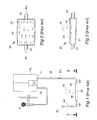
- the water heater 10 is made of a metal heat absorbing slab 20, which comprises a hollow chamber 21 with a top surface 24, a water inlet pipe 23 and a water outlet pipe 22 such that said hollow chamber 21, which allows cold tap water W1 flows therein, has one end thereof with water outlet pipe 22 connected to a water intake 11 of the water heater 10 and the other end thereof with water inlet pipe 23 connected to a source of cold tap water W1 (as shown in FIGS. 1 and 2 ).
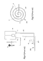
- FIGS. 4 and 5 show another embodiment for the water heater 10 of a metal heat absorbing slab 200 .
- the metal heat absorbing slab 200 comprises a spiral metal tube 201 having multiple continual coils with a gap S for each pair of adjacent coils, one end thereof with water outlet pipe 22 connected to a water intake 11 of the water heater 10 and the other end thereof with water inlet pipe 23 connected to a source of cold tap water W1 .
- the operation for the metal heat absorbing slab 200 is recapped below: Firstly, upon a shower user M starting shower, certain hot shower water W , which comes from the water heater 10 and flow through a water outlet pipe 12, will spray out of the shower sprayer 13; Secondly, the hot shower water W will drop on the top surface of the metal heat absorbing slab 200 after shower on the body of the shower user M, meanwhile certain cold tap water W1 will flow into the spiral metal tube 201 of the metal heat absorbing slab 200 via the water inlet pipe 23 to absorb thermal energy of the dropped hot shower water W on the top surface of the metal heat absorbing slab 200 so that the cold tap water W1 becomes warm heat-exchanged water W2 ; Thirdly, the warm heat-exchanged water W2 then flows out of the water outlet pipe 22 of the metal heat absorbing slab 200; and Finally, the warm heat-exchanged water W2 flows into the water heater 10 via the water intake 11 thereof for serving as warm feeding water (as shown in FIG. 4
- the primary object of the present invention is to provide a "heat exchanger for bathing shower" with overall simplified structure and supporting strength to bear normal weight of human body, particularly for one has internal circulation directing means to substantially increase energy saving effect in consequence of considerably improving heat exchanging efficiency so that the heat exchanger fabricated by the present invention not only substantially shortens overall process steps and decreases manufacturing cost without necessity to hire metal welding technicians of high salary with result in reducing selling price for being affordable by the purchasing ability of the consumers and for appealing the purchasing intention of the consumers but also enhance overall energy saving effect and prolong service life span with result in encouraging the purchasing intention of the consumers.
- the present invention not only facilitates promotion and increases popularity of bathing shower heat exchangers, but also achieves environmental protection by energy saving and reduced carbon footprint.
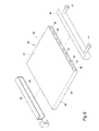
- a "heat exchanger for bathing shower” of the present invention includes a heat exchanging slab 30 and two sealing covers 40 such that one of the sealing covers 40 is created with a water intake 41 and a water outtake 42, wherein:
- the heat exchanging slab 30, which is a flat planar cuboid extruded by alloy metal material, includes a flat top surface 31, a flat bottom surface 32, a front hatch 33, a rear hatch 34, two parallel upright flanks 35, a plurality of parallel water passages 36 penetrated through between the front hatch 33 and rear hatch 34 such that each pair adjacent water passages 36 is partitioned by a septum 37 with a circulating bore 38 created thereon in interlaced stagger manner, which means a bore in upper section of one septum and another bore in lower section of the other septum for each pair of adjacent septa 37 (as shown in FIG.
- each of two sealing covers 40 respectively covers on the front hatch 33 and rear hatch 34 of the heat exchanging slab 30 to closely seal all ends of the water passages 36 in water-tight manner by welding way so that all the water passages 36 together with septa 37 and circulating bores 38 form a close water circulation entirety.
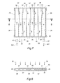
- FIGS. 7 through FIGS.9 illustrate installation and operation method for a heat exchanger for bathing shower of the present invention.
- a water inlet pipe 23 of tap water to the water intake 41 on the sealing cover 40 while connect a water intake 11 of a water heater 10 to the water outtake 42 on the same sealing cover 40 to finish the installation before operation (as shown in FIG. 9 ).
- the plural septa 37 formed between each pair adjacent water passages 36 in the heat exchanging slab 30 of the present invention also serve as props between the flat top surface 31 and flat bottom surface 32 of the heat exchanging slab 30 to be strong enough to completely support normal body weight of a shower user M so that not only the service life span of the heat exchanging slab 30 can be extended due to no indented deformation thereon, but also the shower user M suffered from injure inadvertently incurred by falling down due to such round slippery surface happened as in the metal heat absorbing slab 200 of the China Patent for title "Water heater of energy saving type" in Number of CN201016505 at New Model invention can be avoided because the flat top surface 31 on the heat exchanging slab 30 offers stable platform for shower user M to stand thereon (as shown in FIG. 8 ).
- the circulating bore 38 which is created on each septum 37 and makes every pair adjacent water passages 36 become water communicable mutually, serves as a circulation directing means in the heat exchanging slab 30 (as indicating arrow heads shown in FIG. 7 ) for directing the cold tap water W1 to become a smoothly regular path-oriented stable flow in the heat exchanging slab 30 so that the heat exchanging efficiency of the heat exchanging slab 30 is improved and the energy saving effect of the water heater 10 is substantially increased.
- the heat exchanging slab 30 of the present invention is manufactured by traditional extruding method. Firstly, by means of extruder A, certain melted aluminum alloy is extruded out of extruding die B into a bar of heat exchanging slab 301; Secondly, by means of cutting tool C, the bar of heat exchanging slab 301 is progressively cut into heat exchanging slabs 30 piece by piece; and Finally, as shown in FIG. 10 , the heat exchanging slab 30 of the present invention is manufactured by traditional extruding method. Firstly, by means of extruder A, certain melted aluminum alloy is extruded out of extruding die B into a bar of heat exchanging slab 301; Secondly, by means of cutting tool C, the bar of heat exchanging slab 301 is progressively cut into heat exchanging slabs 30 piece by piece; and Finally, as shown in FIG.
- the overall manufacturing cost of the present invention can be substantially decreased with result in effectively reducing selling price of the product thereof.
- the consumers are more affordable to purchase the "heat exchanger for bathing shower" of the present invention in consequence of the increasing purchasing intention.
- an immediate and noticeable effect for energy saving of electricity and gas consumption in the water heater 10 by promoting usage the "heat exchanger for bathing shower” of the present invention can be quickly achieved.
- FIGS. 12 and 13 show a heat exchanger of cambered for bathing shower in another exemplary embodiment of the present invention.
- the heat exchanger here comprises a cambered heat exchanging slab 50 and two cambered sealing covers 60, wherein said cambered heat exchanging slab 50 includes a cambered top surface 51, a cambered bottom surface 52 with two water intakes 501 and a water outtake 502 beneath, a cambered front hatch 53, a cambered rear hatch 54, two flanks, a plurality of parallel water passages 56 penetrated through between the front hatch 53 and rear hatch 54 such that each pair adjacent water passages 56 is partitioned by a septum 57 with a circulating bore 58 created thereon in interlaced stagger manner, which means a bore in upper section of one septum and another bore in lower section of the other septum for each pair of adjacent septa 57 (as shown in FIG.
- each of two cambered sealing covers 60 respectively covers on the front hatch 53 and rear hatch 54 of the cambered heat exchanging slab 50 to closely seal all ends of the water passages 56 in water-tight manner by welding way so that all the water passages 56 together with septa 57 and circulating bores 58 form a close water circulation entirety to have energy saving effect for the water heater 10.
- the alloy metal material used in the foregoing heat exchanging slab 30 or cambered heat exchanging slab 50 can be replaced by synthetic non-metal compound material with heat conductivity such as carbon fiber for serving in heat exchanging function with hot shower water W to still maintain energy saving effect for the water heater 10.
- FIGS. 14 through 17 show various exemplary embodiments in different combination of variant heat exchangers for bathing shower of the present invention
- FIG. 14 is an exemplary embodiment showing a combination of inverted triangle for three heat exchanging slabs 30 by means of pipes P to properly connect to each water intake and water outtake thereof respectively to form a close water circulation entirety so that the energy saving effect for the water heater 10 is improved as the heat exchanging time with hot shower water W is prolonged.
- FIG. 15 is another exemplary embodiment showing a combination of mutually skew angle for two heat exchanging slabs 30 by means of pipes P to properly connect to each water intake and water outtake thereof respectively to form a close water circulation entirety so that the energy saving effect for the water heater 10 is improved as the heat exchanging time with hot shower water W is prolonged.
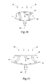
- FIG. 16 is another further exemplary embodiment showing a stack combination of back-to-back arrangement for two cambered heat exchanging slabs 50 by means of pipes P to properly connect to each water intake and water outtake thereof respectively to form a close water circulation entirety so that the energy saving effect for the water heater 10 is improved as the heat exchanging time with hot shower water W is prolonged.
- FIG. 17 is the other exemplary embodiment showing a stack combination of back-to-back arrangement for a heat exchanging slabs 30 in top and a cambered heat exchanging slabs 50 in bottom by means of pipes P to properly connect to each water intake and water outtake thereof respectively to form a close water circulation entirety so that the energy saving effect for the water heater 10 is improved as the heat exchanging time with hot shower water W is prolonged.
- the present invention not only can indeed achieve the purpose of substantially decreasing overall manufacturing cost owing to innovative simplified structure and relatively less manufacturing process, but also the energy saving effect for electricity and gas used in the water heater 10 can be highly improved. Accordingly, the present invention meets the patentable criterion.
Landscapes
- Engineering & Computer Science (AREA)
- Physics & Mathematics (AREA)
- Thermal Sciences (AREA)
- Mechanical Engineering (AREA)
- General Engineering & Computer Science (AREA)
- Heat-Pump Type And Storage Water Heaters (AREA)
- Bathtubs, Showers, And Their Attachments (AREA)
- Devices For Medical Bathing And Washing (AREA)
- Heat-Exchange Devices With Radiators And Conduit Assemblies (AREA)
Applications Claiming Priority (1)
| Application Number | Priority Date | Filing Date | Title |
|---|---|---|---|
| CN2009200562959U CN201449171U (zh) | 2009-05-05 | 2009-05-05 | 列管式节能器 |
Publications (2)
| Publication Number | Publication Date |
|---|---|
| EP2249115A2 true EP2249115A2 (fr) | 2010-11-10 |
| EP2249115A3 EP2249115A3 (fr) | 2013-06-26 |
Family
ID=42504231
Family Applications (1)
| Application Number | Title | Priority Date | Filing Date |
|---|---|---|---|
| EP10161866.8A Withdrawn EP2249115A3 (fr) | 2009-05-05 | 2010-05-04 | Échangeur de chaleur pour douche |
Country Status (4)
| Country | Link |
|---|---|
| US (1) | US20100282453A1 (fr) |
| EP (1) | EP2249115A3 (fr) |
| JP (1) | JP2010261708A (fr) |
| CN (1) | CN201449171U (fr) |
Cited By (4)
| Publication number | Priority date | Publication date | Assignee | Title |
|---|---|---|---|---|
| CN102478367A (zh) * | 2010-11-24 | 2012-05-30 | 蔡应麟 | 淋浴热水用热能交换装置 |
| WO2012068779A1 (fr) * | 2010-11-24 | 2012-05-31 | Cai Yinglin | Dispositif échangeur de chaleur pour eau chaude de douche |
| EP3734210A1 (fr) * | 2019-04-30 | 2020-11-04 | BAE SYSTEMS plc | Échangeur de chaleur |
| WO2020221988A1 (fr) * | 2019-04-30 | 2020-11-05 | Bae Systems Plc | Échangeur de chaleur |
Families Citing this family (5)
| Publication number | Priority date | Publication date | Assignee | Title |
|---|---|---|---|---|
| CN102374798A (zh) * | 2010-08-11 | 2012-03-14 | 海尔集团公司 | 换热器及节能沐浴器 |
| CN108118296A (zh) * | 2017-12-08 | 2018-06-05 | 北京创昱科技有限公司 | 一种冷却板 |
| CN111750722A (zh) * | 2019-03-28 | 2020-10-09 | 宁波团团工业设计有限公司 | 一种用于废弃热水再利用的装置 |
| CN111043879A (zh) * | 2019-12-26 | 2020-04-21 | 广东圣洛威科技有限公司 | 一种集成热水器用的预热装置 |
| CA222016S (en) | 2023-06-08 | 2024-09-06 | Ipex Tech Inc | Heat exchange device |
Citations (1)
| Publication number | Priority date | Publication date | Assignee | Title |
|---|---|---|---|---|
| CN201016505Y (zh) | 2007-02-09 | 2008-02-06 | 陈春华 | 一种节能热水器 |
Family Cites Families (33)
| Publication number | Priority date | Publication date | Assignee | Title |
|---|---|---|---|---|
| US1703655A (en) * | 1925-11-19 | 1929-02-26 | Whitlock Coil Pipe Company | Heat exchanger for recovering heat from waste process water |
| US2170396A (en) * | 1938-02-07 | 1939-08-22 | Farrel Birmingham Co Inc | Temperature-controlling means for rubber mill pans or the like |
| US3220472A (en) * | 1961-04-13 | 1965-11-30 | Dean Products Inc | Heat exchange panel and method of making same |
| US3263242A (en) * | 1963-05-24 | 1966-08-02 | Wesley P Will | Shower bath |
| CH436630A (de) * | 1966-07-07 | 1967-05-31 | Strebelwerk Ag | Heizwand |
| CH523478A (de) * | 1971-10-26 | 1972-05-31 | Gamma Radiatoren Ag | Heizwand |
| DE2855558A1 (de) * | 1978-12-22 | 1980-07-03 | Bosch Gmbh Robert | Waermerueckgewinnungsanlage an einer duscheinrichtung |
| US4344411A (en) * | 1979-06-07 | 1982-08-17 | Dearborn Howard K | Heat exchanger for space heaters |
| US4304292A (en) * | 1979-07-16 | 1981-12-08 | Cardone Jeremiah V | Shower |
| US4291423A (en) * | 1980-03-31 | 1981-09-29 | Wilson Mahlon T | Heat reclamation for shower baths, sinks, and other fluid receiving vessels |
| DE3403488C2 (de) * | 1984-02-01 | 1986-11-20 | Arbonia Ag, Arbon | Heizkörper aus Flachrohren |
| JPS61151289U (fr) * | 1985-03-12 | 1986-09-18 | ||
| GB8627981D0 (en) * | 1986-11-22 | 1986-12-31 | Howard Ind Pipework Services L | Furnace panel |
| US4821793A (en) * | 1987-08-06 | 1989-04-18 | Sheffield Robert D | Tub and shower floor heat exchanger |
| DE4406971A1 (de) * | 1994-03-03 | 1994-10-06 | Roland Empel | Dusch- bzw. Badewannen und Waschbecken mit integriertem Wärmeaustauscher |
| GB2290863A (en) * | 1994-07-02 | 1996-01-10 | David Donald Hayward | Solar heater |
| JP3438087B2 (ja) * | 1995-02-16 | 2003-08-18 | アクトロニクス株式会社 | リボン状プレートヒートパイプ |
| NL1000178C2 (nl) * | 1995-04-19 | 1996-10-22 | Frenger Systemen B V | Verwarmingslichaam en werkwijze voor het vervaardigen van een dergelijk verwarmingslichaam. |
| JP2002098454A (ja) * | 2000-07-21 | 2002-04-05 | Mitsubishi Materials Corp | 液冷ヒートシンク及びその製造方法 |
| JP2001272188A (ja) * | 2000-12-20 | 2001-10-05 | Actronics Co Ltd | 細径トンネルプレートヒートパイプ |
| EP1306126A1 (fr) * | 2001-10-19 | 2003-05-02 | Methanol Casale S.A. | Echangeur de chaleur pour réacteurs chimiques isothermes |
| KR100569175B1 (ko) * | 2002-08-07 | 2006-04-07 | 가부시키가이샤 덴소 | 카운터 스트림 모드 진동유동 열전달 장치 |
| JP2004278138A (ja) * | 2003-03-17 | 2004-10-07 | Sekisui Seikei Ltd | フリーアクセスフロアパネルおよびそれを用いたフリーアクセスパネル |
| EP1687549B1 (fr) * | 2003-11-29 | 2008-05-14 | Erbslöh Aluminium GmbH | Element amortisseur |
| JP4097652B2 (ja) * | 2004-02-10 | 2008-06-11 | 有限会社東京建基工業 | 浴室内洗い場加温設備 |
| TWM250533U (en) * | 2004-02-16 | 2004-11-11 | Forward Electronics Co Ltd | Flow channel structure of collector of liquid-cooling heat dissipating device |
| JP2005274120A (ja) * | 2004-02-24 | 2005-10-06 | Showa Denko Kk | 液冷式冷却板 |
| GB2413842B (en) * | 2004-05-07 | 2006-06-21 | Matthew Rutherford | Heat-exchange units |
| US7849530B2 (en) * | 2005-10-25 | 2010-12-14 | Craig Hendricks | Waste-water heat recovery system |
| CN101264626A (zh) * | 2007-03-15 | 2008-09-17 | 曹树梁 | 陶瓷中空板胶结成型方法及其应用 |
| US20080060796A1 (en) * | 2006-09-12 | 2008-03-13 | Ying Lin Cai | Heat exchange device for hot water of shower and bath |
| SE532498C2 (sv) * | 2007-06-11 | 2010-02-09 | Leif Anders Jilken | Anordning vid en energiförmedlare |
| TW201036527A (en) * | 2009-03-19 | 2010-10-01 | Acbel Polytech Inc | Large-area liquid-cooled heat-dissipation device |
-
2009
- 2009-05-05 CN CN2009200562959U patent/CN201449171U/zh not_active Expired - Fee Related
-
2010
- 2010-05-04 US US12/662,795 patent/US20100282453A1/en not_active Abandoned
- 2010-05-04 EP EP10161866.8A patent/EP2249115A3/fr not_active Withdrawn
- 2010-05-06 JP JP2010106504A patent/JP2010261708A/ja active Pending
Patent Citations (1)
| Publication number | Priority date | Publication date | Assignee | Title |
|---|---|---|---|---|
| CN201016505Y (zh) | 2007-02-09 | 2008-02-06 | 陈春华 | 一种节能热水器 |
Cited By (5)
| Publication number | Priority date | Publication date | Assignee | Title |
|---|---|---|---|---|
| CN102478367A (zh) * | 2010-11-24 | 2012-05-30 | 蔡应麟 | 淋浴热水用热能交换装置 |
| WO2012068779A1 (fr) * | 2010-11-24 | 2012-05-31 | Cai Yinglin | Dispositif échangeur de chaleur pour eau chaude de douche |
| CN102478367B (zh) * | 2010-11-24 | 2014-02-12 | 蔡应麟 | 淋浴热水用热能交换装置 |
| EP3734210A1 (fr) * | 2019-04-30 | 2020-11-04 | BAE SYSTEMS plc | Échangeur de chaleur |
| WO2020221988A1 (fr) * | 2019-04-30 | 2020-11-05 | Bae Systems Plc | Échangeur de chaleur |
Also Published As
| Publication number | Publication date |
|---|---|
| CN201449171U (zh) | 2010-05-05 |
| EP2249115A3 (fr) | 2013-06-26 |
| JP2010261708A (ja) | 2010-11-18 |
| US20100282453A1 (en) | 2010-11-11 |
Similar Documents
| Publication | Publication Date | Title |
|---|---|---|
| EP2249115A2 (fr) | Échangeur de chaleur pour douche | |
| EP1840481B1 (fr) | Appareil et procédé pour l'introduction et le retrait d'eau dans un chauffe-eau | |
| CN201983660U (zh) | 淋浴热水用热能交换装置 | |
| TW200719806A (en) | Water cooling head and manufacturing method thereof | |
| US20120125587A1 (en) | Heat exchanger for bathing shower | |
| CN204064036U (zh) | 内衬铸铁管的压铸型暖气片 | |
| CN101846393A (zh) | 一种洗头废水余热回收结构 | |
| CN208901928U (zh) | 一种换热器 | |
| CN2504594Y (zh) | 薄板换热器 | |
| CN202361634U (zh) | 用于电开水器的冷热水交换器 | |
| CN102478367B (zh) | 淋浴热水用热能交换装置 | |
| CN205897897U (zh) | 一种钢制板式散热器 | |
| CN109910332A (zh) | 薄膜生产线 | |
| CN202083264U (zh) | 闭式冷却塔防冻冷却器用组合散热管 | |
| CN202229627U (zh) | 钢制高频焊螺旋翅片管散热器 | |
| ITMI20080519A1 (it) | Sistema e metodo di raffreddamento di un tamburo rotabile | |
| CN201964601U (zh) | 电热水器的双内胆结构 | |
| CN201998415U (zh) | 一种管材定径套装置 | |
| CN208403233U (zh) | 一种挤压膨化机冷却装置 | |
| CN204987958U (zh) | 深度螺旋槽换热管换热器 | |
| CN206981446U (zh) | 铝型材挤压机冷却装置 | |
| CN104677141A (zh) | 饮水机的热交换器及包含其的饮水机 | |
| CN205528609U (zh) | 重油催化装置 | |
| CN201611230U (zh) | 淋浴热能交换器 | |
| CN203731915U (zh) | 换热内管和平行流换热器 |
Legal Events
| Date | Code | Title | Description |
|---|---|---|---|
| PUAI | Public reference made under article 153(3) epc to a published international application that has entered the european phase |
Free format text: ORIGINAL CODE: 0009012 |
|
| 17P | Request for examination filed |
Effective date: 20100504 |
|
| AK | Designated contracting states |
Kind code of ref document: A2 Designated state(s): AL AT BE BG CH CY CZ DE DK EE ES FI FR GB GR HR HU IE IS IT LI LT LU LV MC MK MT NL NO PL PT RO SE SI SK SM TR |
|
| AX | Request for extension of the european patent |
Extension state: BA ME RS |
|
| PUAL | Search report despatched |
Free format text: ORIGINAL CODE: 0009013 |
|
| AK | Designated contracting states |
Kind code of ref document: A3 Designated state(s): AL AT BE BG CH CY CZ DE DK EE ES FI FR GB GR HR HU IE IS IT LI LT LU LV MC MK MT NL NO PL PT RO SE SI SK SM TR |
|
| AX | Request for extension of the european patent |
Extension state: BA ME RS |
|
| RIC1 | Information provided on ipc code assigned before grant |
Ipc: F28D 9/00 20060101AFI20130517BHEP Ipc: F28D 1/02 20060101ALI20130517BHEP Ipc: F28F 3/12 20060101ALI20130517BHEP Ipc: F28D 21/00 20060101ALI20130517BHEP |
|
| STAA | Information on the status of an ep patent application or granted ep patent |
Free format text: STATUS: THE APPLICATION IS DEEMED TO BE WITHDRAWN |
|
| 18D | Application deemed to be withdrawn |
Effective date: 20140103 |