EP2249217B1 - Appareil d'automatisation et système d'automatisation - Google Patents
Appareil d'automatisation et système d'automatisation Download PDFInfo
- Publication number
- EP2249217B1 EP2249217B1 EP09159775.7A EP09159775A EP2249217B1 EP 2249217 B1 EP2249217 B1 EP 2249217B1 EP 09159775 A EP09159775 A EP 09159775A EP 2249217 B1 EP2249217 B1 EP 2249217B1
- Authority
- EP
- European Patent Office
- Prior art keywords
- unit
- automation device
- functional unit
- network
- address space
- Prior art date
- Legal status (The legal status is an assumption and is not a legal conclusion. Google has not performed a legal analysis and makes no representation as to the accuracy of the status listed.)
- Not-in-force
Links
Images


Classifications
-
- G—PHYSICS
- G05—CONTROLLING; REGULATING
- G05B—CONTROL OR REGULATING SYSTEMS IN GENERAL; FUNCTIONAL ELEMENTS OF SUCH SYSTEMS; MONITORING OR TESTING ARRANGEMENTS FOR SUCH SYSTEMS OR ELEMENTS
- G05B19/00—Program-control systems
- G05B19/02—Program-control systems electric
- G05B19/04—Program control other than numerical control, i.e. in sequence controllers or logic controllers
- G05B19/042—Program control other than numerical control, i.e. in sequence controllers or logic controllers using digital processors
Definitions
- the invention relates to an automation device comprising a first functional unit, a second functional unit, a first network connection for connection to a first data network and a bus master unit for connecting a peripheral component.
- Peripherals are, for example, input / output modules or additional sensor modules. Input / output signals of the periphery are processed by the automation device itself or forwarded or interconnected to a higher-level arithmetic unit. Preferably, this interconnection is realized by means of a first data network.
- the first data network is also referred to as the primary color system.
- the other part of the periphery is to be assigned to the superordinate arithmetic unit, also called host system.
- a primary bus device for connecting additional peripherals to the higher-order arithmetic unit can be connected to the primary bus system.
- the WO 00/19286 discloses a higher-level control which communicates as a bus master via a fieldbus with an automation device. This has its own processing functionality for fast response times with peripheral components connected to it. In addition, the automation device also supplies input and output functionality to the higher-level controller.
- Automation devices are known that have realized a slave connection for Profibus via virtual modules.
- This slave connection is essentially limited to the user data.
- a user who wants to configure the programmable controller for a particular industrial application must create two separate configurations, one for the slave on a host system and one for the actual automation device.
- a coupling between the I / O and the higher-level arithmetic unit must be configured.
- the accesses to the periphery of A user program must be programmed and the data copied from or to virtual modules. The disadvantage of this is that a reaction time of the periphery, which is controlled by the higher-level arithmetic unit, is correspondingly high.
- the first functional unit has a first interface unit, which is associated with a first network address
- the second functional unit has a second interface unit, which is assigned a second network address
- a distribution means an address space of Peripheral component is logically split and a first address space as a separate part of the address space of a connectable via the first network connection higher-level arithmetic unit is directly assigned.
- the primary bus device functionality should have the same properties that a standard device offers without preprocessing.
- the functional units are largely decoupled from each other.
- two independent interface units are provided with their own network addresses.
- the network addresses are preferably provided as IP addresses.
- the automation device has two independent functions with its two functional units.
- the automation device is divided into two logical devices by means of the two functional units, for each interface unit exists its own IP address, which is also visible in the first data network. These two logical devices are combined to form a multifunctional automation device.
- the first interface unit has a first network switch, to which a first data line is connected, which couples the first functional unit to the second functional unit.
- a network switch a switch is preferably used, which enables a coupling via the first network connection to the first data network while simultaneously realizing a communication coupling via the first data line to the second functional unit.
- An access path from a higher-order arithmetic unit via the first functional unit into the second functional unit is realized with the data-related coupling via the two switches.
- the first functional unit is designed as a control system and the second functional unit as a communication unit for user data connection.
- the second functional unit is designed as a control system and the first functional unit as a communication unit for user data connection.
- a control system is to be understood preferably a programmable logic controller in an automation device.
- the programmable logic controller is used for the sequence control of an industrial process.
- the communication unit for user data connection is preferably designed as a DP slave.
- Such a DP slave enables the data connection of distributed peripheral components (DP).
- DP distributed peripheral components
- These distributed peripheral components may be, for example, input / output modules for receiving and outputting input and output signals, as required in an industrial process for actuators and sensors.
- the functional unit which is configured as a control system, has the bus master unit.
- the bus master unit is used to connect peripheral components, while peripheral components can be both centrally located on an automation device input / output modules or decentralized in the industrial manufacturing process distributed peripheral components, which are then preferably connected via a fieldbus to the bus master.
- Data and / or input / output values can be buffered in a memory interface.
- This memory interface serves as an interface between the two functional units.
- a processor of the first functional unit can access its memory interface for data exchange via a coupling line via a further processor of the second functional unit.
- the functional unit which is configured as a communication unit, has a second network switch, which is connected to a second data line, the second data line being led to the outside for the additional connection of a data network. It can thus be a direct connection of the respective Function unit can be realized with the outside world without communicating through the other functional unit.
- the splitting means is configured such Logically divide peripheral components and allow a first access path from the arithmetic unit to the first address space and a second access path from the programmable controller to the second address space.
- FIG. 1 an automation system with a computing unit 101, an automation device 100 and a first peripheral component 21 is shown.
- the arithmetic unit 101 which can be regarded as a higher-level host system or as a higher-level host computer, is connected to the automation device 100 via a data network 1 Coupling of data coupled.
- the automation device 100 comprises a first functional unit 11 and a second functional unit 12.
- the functional units 11, 12 represent in the automation apparatus 100 two independent logical devices, namely a control system, such as a programmable logic controller, and a communication unit, such as an automation component for connecting a distributed peripheral ,
- the automation device is designed as a structural unit, wherein a housing, the first functional unit 11 and the second functional unit 12 receives.
- the automation device 100 If the automation device 100 is viewed by the arithmetic unit 101 from the point of view of the first data network 1 (primary network), the automation device 100 of the arithmetic unit 101 turns out to be two logical devices in the considered network topology. This is achieved in that each functional unit has its own network address (IP address) is assigned.
- IP address network address
- An engineering system connected to the first data network with a configuration software for the automation device 100 also sees two logical devices which have to be configured separately with the engineering system.
- the first functional unit has a first network address IP 1 and the second functional unit has a second network address IP 2.
- a distribution means 30 arranged in the automation device 100, an address space of a peripheral component 21 can be logically split.
- the first peripheral component 21 is symbolically divided into a first address space 211 and a second address space 212 by a diagonal.
- Via a second data network 2 the first peripheral component 21 is connected to the automation device 100 in connection. User data can be exchanged via this data connection.
- the address space 211 is spanned, for example, by a series of digital inputs of an input / output module.
- the second address space 212 in this case is spanned by the same digital input / output module, the proportion of the disjoint set this time affecting only the digital outputs.
- the automation device 100 can thus query directly with its first functional unit 11 via a second access path 32, the digital outputs of the input / output module from the address space 212.
- a subarea of a periphery can thus be made available directly to a higher-order arithmetic unit 101 in an advantageous manner without the automation device still being burdened with communication management tasks.
- the automation device 100 is shown in a more detailed architecture 1 according to a first embodiment variant.
- the automation device 100 represented by a dashed line represents a structural unit with a housing, within this housing the first functional unit 11 and the second functional unit 12 are arranged.
- the second functional unit 12 is designed as a communication unit for user data connection.
- the first functional unit 11 has a first network connection 3 and a second network connection 4. Via the network connections 3, 4, the first functional unit 11 is located as a control unit in line with the first data network 1.
- the first data network 1 can also be regarded as a primary bus.
- the second functional unit 12 is connected to the control unit via a first switch 5a integrated in the first interface unit 5 and thus also has a connection to the first data network 1.
- the connection from the first switch 5a to the second functional unit 12 is realized by means of a first data line 17 ,
- the first functional unit 11 has a first processor 11a, which is coupled via a coupling line 16 to a second processor 12a of the second functional unit 12.
- the first processor 11a can exchange data with the second processor 12a, whereby the data can also come from the memory interface 13.
- the memory interface is an interface with buffer functionality between the two processors 11a, 12a.
- a first peripheral component 21, a second peripheral component 22 and a third peripheral component 23 via a second data network 2 to the first functional unit 11 this has a bus master 15.
- a first network address is implemented in the first interface unit 5 and a second network address is implemented in the second interface unit 6.
- a superordinate arithmetic unit 101 connected to the first data network 1 can thus via the first data network 1, the first interface unit 5 with a first IP address IP 1 and via the connection with the first data line 17 of the first interface unit 5 with the second interface unit 6 and the second interface unit implemented in the second interface IP 2 IP 2 detect.
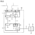
- FIG. 3 a second embodiment in an architecture 2 is shown.
- the automation device 100 now again has a first functional unit 11 and a second functional unit 12.
- the first functional unit 11 is configured as a communication unit and the second functional unit 12 as a control unit.
- the automation device 100 can now be considered as a control CPU with a distributed peripheral device functionality.
- the device is in front of the CPU in terms of circuitry.
- the CPU is connected via a switch integrated in the device.
- This coupling is in the functional unit 11 by means of first interface unit 5, in which a first switch 5a is integrated realized.
- a connection is realized by means of a first data line 17 to the second interface unit 6.
- a second switch 6a is integrated in the second interface unit 6.
- This second switch 6a could, for example, also be designed in duplicate and enable a second connection line to the second switch 6a via a second data line 18, which is led to the additional connection of a data network to the outside.
- the first functional unit 11 also has in this example a first processor 11a and the second functional unit 12 has a second processor 12a, which are connected to one another via a coupling line 16.
- the first functional unit 11 as a communication unit has a memory interface 13 with a RAM module 14.
- a bus master 15 is integrated in the second functional unit 12.
- the bus master 15 is connected to the peripheral units 21, 22, 23 via a second data network 2.
- the second data network 2 may be designed, for example, as a field bus, preferably as a Profibus.
- the second data network 2 is an integrated communication bus on the automation device to which modular input / output modules can be added to expand a decentralized periphery.
- each functional unit 11, 12 can be assigned its specific functionality with respect to the view from the higher-level arithmetic unit 101.
- Both devices namely control unit and communication unit now share via the second data network 2, which can be referred to as a secondary bus, a connected central periphery.
- the actual peripheral resources as seen through the first to third Peripheral components 21, 22, 23 are present only once as a peripheral resource.
- a disjoint distribution of these peripheral resources is realized by assigning two different IP addresses via a corresponding configuration with a project planning tool connected to the automation device 100, such as an engineering system.
- a project planning tool connected to the automation device 100, such as an engineering system.
- the connection between the control unit and the peripheral components 21, 22, 23 is also a forwarding of the Primärbusses to the periphery, which in turn may also consist of one or more functional units possible.
- the dividing means 30 is, for example, a freely programmable component, such as an ASIC or another processor.
- the partitioning means 30 is occupied by the configuration tool with a firmware, in which firmware the distribution information for the periphery is stored.
Landscapes
- Physics & Mathematics (AREA)
- General Physics & Mathematics (AREA)
- Engineering & Computer Science (AREA)
- Automation & Control Theory (AREA)
- Programmable Controllers (AREA)
- Small-Scale Networks (AREA)
Claims (9)
- Appareil ( 100 ) d'automatisation comprenant- une première unité ( 11 ) fonctionnelle,- une deuxième unité ( 12 ) fonctionnelle,- une première connexion ( 3 ) de réseau pour la connexion à un premier réseau ( 1 ) de données,- une unité ( 15 ) maître de bus pour la connexion d'un composant ( 21, 22, 23 ) périphérique,- caractérisé en ce que la première unité ( 11 ) fonctionnelle a une première unité ( 5 ) d'interface, à laquelle est associée une première adresse de réseau,- et la deuxième unité ( 12 ) fonctionnelle a une deuxième unité ( 6 ) d'interface, à laquelle est associée une deuxième adresse de réseau, la première et la deuxième adresses de réseau étant visibles dans le premier réseau ( 1 ) de données et par cela la fonctionnalité des unités ( 11, 12 ) fonctionnelles est associée à la vue d'une unité ( 100 ) informatique supérieure hiérarchiquement,dans lequel à l'aide d'un moyen ( 30 ) de répartition disposé dans l'appareil ( 100 ) d'automatisation, un espace d'adresse du composant ( 21 ) périphérique peut être réparti logiquement et un premier espace ( 211 ) d'adresse peut être associé directement en tant que partie séparée de l'espace d'adresse à l'unité ( 101 ) informatique supérieure hiérarchiquement et pouvant être raccordée par la première connexion ( 3 ) de réseau, la répartition logique dans le premier espace ( 211 ) d'adresse et dans un deuxième espace ( 212 ) d'adresse étant mémorisée comme information de répartition dans des moyens ( 30 ) de répartition de sorte que l'unité ( 101 ) informatique rend possible, par un premier chemin ( 31 ) d'accès, un couplage direct au premier espace ( 211 ) d'adresse et au système ( 100 ) d'automatisation et, par un deuxième chemin ( 32 ) d'accès, une demande directe à partir du deuxième espace ( 212 ) d'adresse de sorte qu'une région partielle d'une périphérie est mise à disposition directement de l'unité ( 101 ) informatique supérieure hiérarchiquement.
- Appareil ( 100 ) d'automatisation suivant la revendication 1,
dans lequel la première unité ( 5 ) d'interface a un premier commutateur ( 5a ) de réseau, auquel est raccordée une première ligne ( 17 ) de données, qui couple la première unité ( 11 ) fonctionnelle à la deuxième unité ( 12 ) fonctionnelle. - Appareil ( 100 ) d'automatisation suivant la revendication 1 ou 2,
dans lequel la première unité ( 11 ) fonctionnelle est constituée en système de commande et la deuxième unité ( 12 ) fonctionnelle en unité de communication pour l'injection de données utiles. - Appareil ( 100 ) d'automatisation suivant la revendication 1 ou 2,
dans lequel la deuxième unité ( 12 ) fonctionnelle est constituée en système de commande et la première unité ( 11 ) fonctionnelle en unité de communication pour l'injection de donnée utile. - Appareil ( 100 ) d'automatisation suivant la revendication 3 ou 4,
dans lequel l'unité ( 11, 12 ) fonctionnelle qui est conformée en système de commande comporte l'unité ( 15 ) maître de bus. - Appareil ( 100 ) d'automatisation suivant la revendication 3 ou 4,
dans lequel l'unité ( 11, 12 ) fonctionnelle qui est conformée en unité de communication comporte une interface ( 13 ) de mémoire. - Appareil ( 100 ) d'automatisation suivant la revendication 5 ou 6,
dans lequel l'unité ( 11, 12 ) fonctionnelle qui est conformée en unité de communication a un deuxième commutateur ( 6a ) de réseau, qui est relié à une deuxième ligne ( 18 ) de données,
la deuxième ligne ( 18 ) de données allant vers l'extérieur pour la connexion supplémentaire d'un réseau de données. - Appareil ( 100 ) d'automatisation suivant l'une des revendications 1 à 7 conformée en unité de construction ayant un boîtier.
- Système d'automatisation comprenant une unité ( 101 ) informatique et un appareil ( 100 ) d'automatisation suivant l'une des revendications précédentes, qui sont reliées par un premier réseau ( 1 ) de données, un deuxième réseau ( 2 ) de données reliant l'appareil ( 100 ) d'automatisation à d'autres composants ( 21, 22, 23 ) périphériques ou à d'autres composants d'automatisation, le moyen ( 30 ) de répartition étant tel qu'il répartit logiquement les composants périphériques et rend possibles un premier chemin ( 31 ) d'accès de l'unité ( 101 ) informatique au premier espace ( 211 ) d'adresse et un deuxième chemin ( 32 ) d'accès de l'appareil ( 100 ) d'automatisation au deuxième espace ( 212 ) d'adresse.
Priority Applications (3)
| Application Number | Priority Date | Filing Date | Title |
|---|---|---|---|
| EP09159775.7A EP2249217B1 (fr) | 2009-05-08 | 2009-05-08 | Appareil d'automatisation et système d'automatisation |
| CN201010145568.4A CN101881946B (zh) | 2009-05-08 | 2010-04-02 | 自动化设备和自动化系统 |
| US12/775,129 US8788609B2 (en) | 2009-05-08 | 2010-05-06 | Automation device and automation system |
Applications Claiming Priority (1)
| Application Number | Priority Date | Filing Date | Title |
|---|---|---|---|
| EP09159775.7A EP2249217B1 (fr) | 2009-05-08 | 2009-05-08 | Appareil d'automatisation et système d'automatisation |
Publications (2)
| Publication Number | Publication Date |
|---|---|
| EP2249217A1 EP2249217A1 (fr) | 2010-11-10 |
| EP2249217B1 true EP2249217B1 (fr) | 2013-04-24 |
Family
ID=40874864
Family Applications (1)
| Application Number | Title | Priority Date | Filing Date |
|---|---|---|---|
| EP09159775.7A Not-in-force EP2249217B1 (fr) | 2009-05-08 | 2009-05-08 | Appareil d'automatisation et système d'automatisation |
Country Status (3)
| Country | Link |
|---|---|
| US (1) | US8788609B2 (fr) |
| EP (1) | EP2249217B1 (fr) |
| CN (1) | CN101881946B (fr) |
Families Citing this family (4)
| Publication number | Priority date | Publication date | Assignee | Title |
|---|---|---|---|---|
| EP2456124A1 (fr) * | 2010-11-23 | 2012-05-23 | Siemens Aktiengesellschaft | Ingénierie d'interface de capteur |
| US9389606B2 (en) * | 2011-11-11 | 2016-07-12 | Rockwell Automation Technologies, Inc. | Agile control model system and method |
| EP3141970B1 (fr) * | 2015-09-09 | 2017-11-15 | Siemens Aktiengesellschaft | Peripherie decentralisee |
| CN107370839A (zh) * | 2017-06-29 | 2017-11-21 | 北京东土科技股份有限公司 | 工业现场设备的寻址方法及相关装置、系统 |
Family Cites Families (30)
| Publication number | Priority date | Publication date | Assignee | Title |
|---|---|---|---|---|
| US5734858A (en) * | 1994-10-24 | 1998-03-31 | Microsoft Corporation | Method and apparatus for simulating banked memory as a linear address space |
| US5980078A (en) * | 1997-02-14 | 1999-11-09 | Fisher-Rosemount Systems, Inc. | Process control system including automatic sensing and automatic configuration of devices |
| US5950014A (en) * | 1997-03-21 | 1999-09-07 | Lsi Logic Corporation | Methodology for pull model invocation |
| DE59903495D1 (de) * | 1998-09-30 | 2003-01-02 | Siemens Ag | Vorrichtung zur steuerung und/oder überwachung externer technischer prozesse |
| US6754720B1 (en) * | 2001-03-02 | 2004-06-22 | Adaptec, Inc. | Automatic addressing of expanders in I/O subsystem |
| DE10113261C2 (de) * | 2001-03-16 | 2003-07-10 | Siemens Ag | Synchrones, getaktetes Kommunikationssystem mit dezentralen Ein-/Ausgabe-Baugruppen und Verfahren zur Einbindung dezentraler Ein-/Ausgabe-Baugruppen in ein solches System |
| US6662251B2 (en) * | 2001-03-26 | 2003-12-09 | International Business Machines Corporation | Selective targeting of transactions to devices on a shared bus |
| US7349392B2 (en) * | 2001-09-14 | 2008-03-25 | Hewlett-Packard Development Company, L.P. | Assigning IP addresses in an internet data center |
| DE10163342A1 (de) * | 2001-12-21 | 2003-07-10 | Elektro Beckhoff Gmbh Unterneh | Datenübertragungsverfahren, serielles Bussystem und Anschalteinheit für einen passiven Busteilnehmer |
| DE10309168A1 (de) | 2003-02-28 | 2004-09-09 | Siemens Ag | Effiziente implementierung einfacher Knoten in einem geswitchten Netz |
| US20070058654A1 (en) * | 2003-07-10 | 2007-03-15 | Johann Arnold | Arrangement and coupling device for securing data access |
| EP1500994A1 (fr) * | 2003-07-22 | 2005-01-26 | Siemens Aktiengesellschaft | Dispositif de couplage pour connecter trois systèmes de bus |
| DE10335989B4 (de) * | 2003-08-01 | 2019-07-11 | Kw-Software Gmbh | Online-Änderungen von CIL-Code-Programmen für die Industrieautomatisierung |
| DE102004007233B3 (de) * | 2004-02-13 | 2005-05-19 | Siemens Ag | Verfahren zum Installieren einer Automatisierungskomponente und entsprechendes Automatisierungssystem |
| EP1589433A1 (fr) * | 2004-04-20 | 2005-10-26 | Ecole Polytechnique Federale De Lausanne | Fenêtre de mémoire virtuelle avec support de pre-extraction dynamique |
| WO2006014554A2 (fr) * | 2004-07-07 | 2006-02-09 | University Of Maryland | Procede et systeme pour surveillance d'integrite de memoire systeme |
| DE102004041823B4 (de) | 2004-08-27 | 2014-03-20 | Robert Bosch Gmbh | Kommunikationsbaustein mit einem Kommunikationsschnittstellenelement und Kommunikationsschnittstellenelement |
| US20060123111A1 (en) * | 2004-12-02 | 2006-06-08 | Frank Dea | Method, system and computer program product for transitioning network traffic between logical partitions in one or more data processing systems |
| US20060222608A1 (en) | 2005-04-01 | 2006-10-05 | Agricultural Research Institute | Edible tremella polysaccharide for skin care |
| US7636797B2 (en) * | 2005-05-04 | 2009-12-22 | Atmel Corporation | LPC configuration sharing method |
| CN101208674B (zh) * | 2005-06-23 | 2012-07-04 | 赫优讯自动化系统有限公司 | 用于开放式自动化系统的总线用户的数据通信的方法和装置 |
| US7430630B2 (en) * | 2005-10-27 | 2008-09-30 | International Business Machines Corporation | Routing mechanism in PCI multi-host topologies using destination ID field |
| DE102005054202B3 (de) * | 2005-11-14 | 2007-04-19 | Siemens Ag | Serielles Bussystem, Teilnehmervorrichtung und an die Teilnehmervorrichtung anschließbare Eingabe-/Ausgabekarte |
| US7457900B2 (en) * | 2006-06-20 | 2008-11-25 | Intel Corporation | Method for discovering and partitioning PCI devices |
| US8392726B2 (en) * | 2006-12-20 | 2013-03-05 | Stmicroelectronics S.A. | Protection of memory areas |
| US7865252B2 (en) * | 2007-01-26 | 2011-01-04 | Autani Corporation | Upgradeable automation devices, systems, architectures, and methods |
| EP2119124B1 (fr) * | 2007-01-29 | 2011-09-07 | Siemens Aktiengesellschaft | Procédé de fonctionnement d'un composant de réseau dans un système d'automatisation, système d'automatisation pourvu d'un composant de réseau pouvant fonctionner suivant le procédé, procédé de transmission de données dans un système d'automatisation ayant des appareils de communication dont au moins certains fonctionnent en tant que composants de réseau selon le procédé de fonctionnement d'un composant de réseau, ainsi que programme informatique et produit programme informatique correspondants |
| US7882327B2 (en) * | 2007-07-31 | 2011-02-01 | Advanced Micro Devices, Inc. | Communicating between partitions in a statically partitioned multiprocessing system |
| DE102007039425A1 (de) * | 2007-08-21 | 2009-02-26 | Beckhoff Automation Gmbh | Steuerknoten und Steuerung |
| US8170722B1 (en) * | 2010-12-09 | 2012-05-01 | Elbex Video Ltd. | Method and apparatus for coding and linking electrical appliances for control and status report |
-
2009
- 2009-05-08 EP EP09159775.7A patent/EP2249217B1/fr not_active Not-in-force
-
2010
- 2010-04-02 CN CN201010145568.4A patent/CN101881946B/zh not_active Expired - Fee Related
- 2010-05-06 US US12/775,129 patent/US8788609B2/en active Active
Also Published As
| Publication number | Publication date |
|---|---|
| US20100287255A1 (en) | 2010-11-11 |
| CN101881946B (zh) | 2014-11-19 |
| US8788609B2 (en) | 2014-07-22 |
| CN101881946A (zh) | 2010-11-10 |
| EP2249217A1 (fr) | 2010-11-10 |
Similar Documents
| Publication | Publication Date | Title |
|---|---|---|
| EP2588928B1 (fr) | Système de communication permettant de relier des appareils de terrain à un dispositif de commande superposé | |
| DE10211939A1 (de) | Kopplungsvorrichtung zum Ankoppeln von Geräten an ein Bussystem | |
| DE102011107318A1 (de) | Verfahren zur Konfigurierung eines Kommunikationsschnittstellenmoduls in einem Steuerungs- oder Automatisierungssystem | |
| DE102005055000A1 (de) | Modulares Avioniksystem eines Flugzeuges | |
| DE102016000126A1 (de) | Serielles Bussystem mit Koppelmodulen | |
| EP2520991A1 (fr) | Procédé d'accès commandé au comportement d'un sous-module | |
| EP2249217A1 (fr) | Appareil d'automatisation et système d'automatisation | |
| EP4038511B1 (fr) | Unité d'entrée/sortie pour la capture de données dans un système de bus de terrain | |
| EP2895925B1 (fr) | Système de bus de terrain en cascade | |
| EP2092398B1 (fr) | Appareil de terrain bifilaire pour la technique d'automatisation de procédés destinée à connecter au moins un élément de capteur | |
| EP0792078B1 (fr) | Système d'interface pour capteurs-actionneurs | |
| EP2682827B1 (fr) | Système d'automatisation avec un dispositif d'entrées partagé | |
| DE102011107322A1 (de) | Kommunikationsschnittstellenmodul für ein Automatisierungssystem | |
| WO2012110541A1 (fr) | Procédé de transmission de données par le biais d'un bus de données série synchrone | |
| WO2019161820A1 (fr) | Unité de communication intégrée | |
| EP1646919A1 (fr) | Systeme de couplage destine a trois systemes de bus | |
| DE102012214846A1 (de) | Automatisierungssystem mit dezentralisierten Steuerungsfunktionalitäten in E-/A-Baugruppen | |
| EP1493067B1 (fr) | Procede de projection et/ou d'utilisation d'un systeme d'automatisation | |
| EP1400882A2 (fr) | Dispositif d'automatisation et/ou de commande de machines-outils ou de machines de production | |
| DE102016015616B4 (de) | Modul-System mit Busanbindung und Direkt-Drahtverbindung | |
| DE102018211702A1 (de) | Steuereinheit für ein Fahrassistenzsystem eines Kraftfahrzeugs | |
| EP4517540A1 (fr) | Agencement pour un dispositif de calcul électronique ainsi que procédé de fonctionnement d'un agencement | |
| EP3632066B1 (fr) | Préchargement d'instructions | |
| EP2642698A1 (fr) | Dispositif AS-i | |
| DE102006052244A1 (de) | Robotersteuereinrichtung |
Legal Events
| Date | Code | Title | Description |
|---|---|---|---|
| PUAI | Public reference made under article 153(3) epc to a published international application that has entered the european phase |
Free format text: ORIGINAL CODE: 0009012 |
|
| AK | Designated contracting states |
Kind code of ref document: A1 Designated state(s): AT BE BG CH CY CZ DE DK EE ES FI FR GB GR HR HU IE IS IT LI LT LU LV MC MK MT NL NO PL PT RO SE SI SK TR |
|
| AX | Request for extension of the european patent |
Extension state: AL BA RS |
|
| 17P | Request for examination filed |
Effective date: 20110509 |
|
| 17Q | First examination report despatched |
Effective date: 20110530 |
|
| GRAP | Despatch of communication of intention to grant a patent |
Free format text: ORIGINAL CODE: EPIDOSNIGR1 |
|
| GRAS | Grant fee paid |
Free format text: ORIGINAL CODE: EPIDOSNIGR3 |
|
| RAP1 | Party data changed (applicant data changed or rights of an application transferred) |
Owner name: SIEMENS AKTIENGESELLSCHAFT |
|
| GRAA | (expected) grant |
Free format text: ORIGINAL CODE: 0009210 |
|
| AK | Designated contracting states |
Kind code of ref document: B1 Designated state(s): AT BE BG CH CY CZ DE DK EE ES FI FR GB GR HR HU IE IS IT LI LT LU LV MC MK MT NL NO PL PT RO SE SI SK TR |
|
| REG | Reference to a national code |
Ref country code: GB Ref legal event code: FG4D Free format text: NOT ENGLISH |
|
| REG | Reference to a national code |
Ref country code: CH Ref legal event code: EP |
|
| REG | Reference to a national code |
Ref country code: AT Ref legal event code: REF Ref document number: 608946 Country of ref document: AT Kind code of ref document: T Effective date: 20130515 |
|
| REG | Reference to a national code |
Ref country code: IE Ref legal event code: FG4D Free format text: LANGUAGE OF EP DOCUMENT: GERMAN |
|
| REG | Reference to a national code |
Ref country code: DE Ref legal event code: R096 Ref document number: 502009006920 Country of ref document: DE Effective date: 20130620 |
|
| REG | Reference to a national code |
Ref country code: LT Ref legal event code: MG4D |
|
| REG | Reference to a national code |
Ref country code: NL Ref legal event code: VDEP Effective date: 20130424 |
|
| PG25 | Lapsed in a contracting state [announced via postgrant information from national office to epo] |
Ref country code: GR Free format text: LAPSE BECAUSE OF FAILURE TO SUBMIT A TRANSLATION OF THE DESCRIPTION OR TO PAY THE FEE WITHIN THE PRESCRIBED TIME-LIMIT Effective date: 20130725 Ref country code: IS Free format text: LAPSE BECAUSE OF FAILURE TO SUBMIT A TRANSLATION OF THE DESCRIPTION OR TO PAY THE FEE WITHIN THE PRESCRIBED TIME-LIMIT Effective date: 20130824 Ref country code: SI Free format text: LAPSE BECAUSE OF FAILURE TO SUBMIT A TRANSLATION OF THE DESCRIPTION OR TO PAY THE FEE WITHIN THE PRESCRIBED TIME-LIMIT Effective date: 20130424 Ref country code: NO Free format text: LAPSE BECAUSE OF FAILURE TO SUBMIT A TRANSLATION OF THE DESCRIPTION OR TO PAY THE FEE WITHIN THE PRESCRIBED TIME-LIMIT Effective date: 20130724 Ref country code: LT Free format text: LAPSE BECAUSE OF FAILURE TO SUBMIT A TRANSLATION OF THE DESCRIPTION OR TO PAY THE FEE WITHIN THE PRESCRIBED TIME-LIMIT Effective date: 20130424 Ref country code: PT Free format text: LAPSE BECAUSE OF FAILURE TO SUBMIT A TRANSLATION OF THE DESCRIPTION OR TO PAY THE FEE WITHIN THE PRESCRIBED TIME-LIMIT Effective date: 20130826 Ref country code: SE Free format text: LAPSE BECAUSE OF FAILURE TO SUBMIT A TRANSLATION OF THE DESCRIPTION OR TO PAY THE FEE WITHIN THE PRESCRIBED TIME-LIMIT Effective date: 20130424 Ref country code: FI Free format text: LAPSE BECAUSE OF FAILURE TO SUBMIT A TRANSLATION OF THE DESCRIPTION OR TO PAY THE FEE WITHIN THE PRESCRIBED TIME-LIMIT Effective date: 20130424 Ref country code: ES Free format text: LAPSE BECAUSE OF FAILURE TO SUBMIT A TRANSLATION OF THE DESCRIPTION OR TO PAY THE FEE WITHIN THE PRESCRIBED TIME-LIMIT Effective date: 20130804 |
|
| PG25 | Lapsed in a contracting state [announced via postgrant information from national office to epo] |
Ref country code: CY Free format text: LAPSE BECAUSE OF FAILURE TO SUBMIT A TRANSLATION OF THE DESCRIPTION OR TO PAY THE FEE WITHIN THE PRESCRIBED TIME-LIMIT Effective date: 20130424 Ref country code: HR Free format text: LAPSE BECAUSE OF FAILURE TO SUBMIT A TRANSLATION OF THE DESCRIPTION OR TO PAY THE FEE WITHIN THE PRESCRIBED TIME-LIMIT Effective date: 20130424 Ref country code: PL Free format text: LAPSE BECAUSE OF FAILURE TO SUBMIT A TRANSLATION OF THE DESCRIPTION OR TO PAY THE FEE WITHIN THE PRESCRIBED TIME-LIMIT Effective date: 20130424 Ref country code: LV Free format text: LAPSE BECAUSE OF FAILURE TO SUBMIT A TRANSLATION OF THE DESCRIPTION OR TO PAY THE FEE WITHIN THE PRESCRIBED TIME-LIMIT Effective date: 20130424 Ref country code: BG Free format text: LAPSE BECAUSE OF FAILURE TO SUBMIT A TRANSLATION OF THE DESCRIPTION OR TO PAY THE FEE WITHIN THE PRESCRIBED TIME-LIMIT Effective date: 20130724 |
|
| BERE | Be: lapsed |
Owner name: SIEMENS A.G. Effective date: 20130531 |
|
| REG | Reference to a national code |
Ref country code: CH Ref legal event code: PL |
|
| PG25 | Lapsed in a contracting state [announced via postgrant information from national office to epo] |
Ref country code: LI Free format text: LAPSE BECAUSE OF NON-PAYMENT OF DUE FEES Effective date: 20130531 Ref country code: CH Free format text: LAPSE BECAUSE OF NON-PAYMENT OF DUE FEES Effective date: 20130531 Ref country code: MC Free format text: LAPSE BECAUSE OF FAILURE TO SUBMIT A TRANSLATION OF THE DESCRIPTION OR TO PAY THE FEE WITHIN THE PRESCRIBED TIME-LIMIT Effective date: 20130424 Ref country code: DK Free format text: LAPSE BECAUSE OF FAILURE TO SUBMIT A TRANSLATION OF THE DESCRIPTION OR TO PAY THE FEE WITHIN THE PRESCRIBED TIME-LIMIT Effective date: 20130424 Ref country code: CZ Free format text: LAPSE BECAUSE OF FAILURE TO SUBMIT A TRANSLATION OF THE DESCRIPTION OR TO PAY THE FEE WITHIN THE PRESCRIBED TIME-LIMIT Effective date: 20130424 Ref country code: SK Free format text: LAPSE BECAUSE OF FAILURE TO SUBMIT A TRANSLATION OF THE DESCRIPTION OR TO PAY THE FEE WITHIN THE PRESCRIBED TIME-LIMIT Effective date: 20130424 Ref country code: EE Free format text: LAPSE BECAUSE OF FAILURE TO SUBMIT A TRANSLATION OF THE DESCRIPTION OR TO PAY THE FEE WITHIN THE PRESCRIBED TIME-LIMIT Effective date: 20130424 |
|
| REG | Reference to a national code |
Ref country code: IE Ref legal event code: MM4A |
|
| PG25 | Lapsed in a contracting state [announced via postgrant information from national office to epo] |
Ref country code: BE Free format text: LAPSE BECAUSE OF NON-PAYMENT OF DUE FEES Effective date: 20130531 Ref country code: NL Free format text: LAPSE BECAUSE OF FAILURE TO SUBMIT A TRANSLATION OF THE DESCRIPTION OR TO PAY THE FEE WITHIN THE PRESCRIBED TIME-LIMIT Effective date: 20130424 Ref country code: RO Free format text: LAPSE BECAUSE OF FAILURE TO SUBMIT A TRANSLATION OF THE DESCRIPTION OR TO PAY THE FEE WITHIN THE PRESCRIBED TIME-LIMIT Effective date: 20130424 |
|
| PLBE | No opposition filed within time limit |
Free format text: ORIGINAL CODE: 0009261 |
|
| STAA | Information on the status of an ep patent application or granted ep patent |
Free format text: STATUS: NO OPPOSITION FILED WITHIN TIME LIMIT |
|
| 26N | No opposition filed |
Effective date: 20140127 |
|
| PG25 | Lapsed in a contracting state [announced via postgrant information from national office to epo] |
Ref country code: IE Free format text: LAPSE BECAUSE OF NON-PAYMENT OF DUE FEES Effective date: 20130508 |
|
| REG | Reference to a national code |
Ref country code: DE Ref legal event code: R097 Ref document number: 502009006920 Country of ref document: DE Effective date: 20140127 |
|
| PG25 | Lapsed in a contracting state [announced via postgrant information from national office to epo] |
Ref country code: MT Free format text: LAPSE BECAUSE OF FAILURE TO SUBMIT A TRANSLATION OF THE DESCRIPTION OR TO PAY THE FEE WITHIN THE PRESCRIBED TIME-LIMIT Effective date: 20130424 |
|
| PG25 | Lapsed in a contracting state [announced via postgrant information from national office to epo] |
Ref country code: TR Free format text: LAPSE BECAUSE OF FAILURE TO SUBMIT A TRANSLATION OF THE DESCRIPTION OR TO PAY THE FEE WITHIN THE PRESCRIBED TIME-LIMIT Effective date: 20130424 |
|
| REG | Reference to a national code |
Ref country code: AT Ref legal event code: MM01 Ref document number: 608946 Country of ref document: AT Kind code of ref document: T Effective date: 20140508 |
|
| PG25 | Lapsed in a contracting state [announced via postgrant information from national office to epo] |
Ref country code: MK Free format text: LAPSE BECAUSE OF FAILURE TO SUBMIT A TRANSLATION OF THE DESCRIPTION OR TO PAY THE FEE WITHIN THE PRESCRIBED TIME-LIMIT Effective date: 20130424 Ref country code: LU Free format text: LAPSE BECAUSE OF NON-PAYMENT OF DUE FEES Effective date: 20130508 Ref country code: HU Free format text: LAPSE BECAUSE OF FAILURE TO SUBMIT A TRANSLATION OF THE DESCRIPTION OR TO PAY THE FEE WITHIN THE PRESCRIBED TIME-LIMIT; INVALID AB INITIO Effective date: 20090508 |
|
| PG25 | Lapsed in a contracting state [announced via postgrant information from national office to epo] |
Ref country code: AT Free format text: LAPSE BECAUSE OF NON-PAYMENT OF DUE FEES Effective date: 20140508 |
|
| REG | Reference to a national code |
Ref country code: FR Ref legal event code: PLFP Year of fee payment: 8 |
|
| REG | Reference to a national code |
Ref country code: FR Ref legal event code: PLFP Year of fee payment: 9 |
|
| REG | Reference to a national code |
Ref country code: FR Ref legal event code: PLFP Year of fee payment: 10 |
|
| PGFP | Annual fee paid to national office [announced via postgrant information from national office to epo] |
Ref country code: IT Payment date: 20230523 Year of fee payment: 15 Ref country code: FR Payment date: 20230515 Year of fee payment: 15 Ref country code: DE Payment date: 20220620 Year of fee payment: 15 |
|
| PGFP | Annual fee paid to national office [announced via postgrant information from national office to epo] |
Ref country code: GB Payment date: 20230605 Year of fee payment: 15 |
|
| REG | Reference to a national code |
Ref country code: DE Ref legal event code: R119 Ref document number: 502009006920 Country of ref document: DE |
|
| GBPC | Gb: european patent ceased through non-payment of renewal fee |
Effective date: 20240508 |
|
| PG25 | Lapsed in a contracting state [announced via postgrant information from national office to epo] |
Ref country code: DE Free format text: LAPSE BECAUSE OF NON-PAYMENT OF DUE FEES Effective date: 20241203 |
|
| PG25 | Lapsed in a contracting state [announced via postgrant information from national office to epo] |
Ref country code: FR Free format text: LAPSE BECAUSE OF NON-PAYMENT OF DUE FEES Effective date: 20240531 |
|
| PG25 | Lapsed in a contracting state [announced via postgrant information from national office to epo] |
Ref country code: IT Free format text: LAPSE BECAUSE OF NON-PAYMENT OF DUE FEES Effective date: 20240508 Ref country code: GB Free format text: LAPSE BECAUSE OF NON-PAYMENT OF DUE FEES Effective date: 20240508 |