EP2249285A1 - Verfahren und Programm zum Steuern des Abonnentengeräts und Abonnentengerät - Google Patents
Verfahren und Programm zum Steuern des Abonnentengeräts und Abonnentengerät Download PDFInfo
- Publication number
- EP2249285A1 EP2249285A1 EP10173362A EP10173362A EP2249285A1 EP 2249285 A1 EP2249285 A1 EP 2249285A1 EP 10173362 A EP10173362 A EP 10173362A EP 10173362 A EP10173362 A EP 10173362A EP 2249285 A1 EP2249285 A1 EP 2249285A1
- Authority
- EP
- European Patent Office
- Prior art keywords
- user
- subscriber equipment
- sensor
- control
- output quantity
- Prior art date
- Legal status (The legal status is an assumption and is not a legal conclusion. Google has not performed a legal analysis and makes no representation as to the accuracy of the status listed.)
- Granted
Links
Images


Classifications
-
- G—PHYSICS
- G06—COMPUTING OR CALCULATING; COUNTING
- G06F—ELECTRIC DIGITAL DATA PROCESSING
- G06F1/00—Details not covered by groups G06F3/00 - G06F13/00 and G06F21/00
- G06F1/16—Constructional details or arrangements
- G06F1/1613—Constructional details or arrangements for portable computers
- G06F1/1626—Constructional details or arrangements for portable computers with a single-body enclosure integrating a flat display, e.g. Personal Digital Assistants [PDAs]
-
- G—PHYSICS
- G06—COMPUTING OR CALCULATING; COUNTING
- G06F—ELECTRIC DIGITAL DATA PROCESSING
- G06F1/00—Details not covered by groups G06F3/00 - G06F13/00 and G06F21/00
- G06F1/16—Constructional details or arrangements
- G06F1/1613—Constructional details or arrangements for portable computers
- G06F1/1633—Constructional details or arrangements of portable computers not specific to the type of enclosures covered by groups G06F1/1615 - G06F1/1626
- G06F1/1684—Constructional details or arrangements related to integrated I/O peripherals not covered by groups G06F1/1635 - G06F1/1675
- G06F1/1698—Constructional details or arrangements related to integrated I/O peripherals not covered by groups G06F1/1635 - G06F1/1675 the I/O peripheral being a sending/receiving arrangement to establish a cordless communication link, e.g. radio or infrared link, integrated cellular phone
-
- G—PHYSICS
- G06—COMPUTING OR CALCULATING; COUNTING
- G06F—ELECTRIC DIGITAL DATA PROCESSING
- G06F3/00—Input arrangements for transferring data to be processed into a form capable of being handled by the computer; Output arrangements for transferring data from processing unit to output unit, e.g. interface arrangements
- G06F3/01—Input arrangements or combined input and output arrangements for interaction between user and computer
- G06F3/03—Arrangements for converting the position or the displacement of a member into a coded form
- G06F3/033—Pointing devices displaced or positioned by the user, e.g. mice, trackballs, pens or joysticks; Accessories therefor
- G06F3/0354—Pointing devices displaced or positioned by the user, e.g. mice, trackballs, pens or joysticks; Accessories therefor with detection of two-dimensional [2D] relative movements between the device, or an operating part thereof, and a plane or surface, e.g. 2D mice, trackballs, pens or pucks
- G06F3/03547—Touch pads, in which fingers can move on a surface
-
- G—PHYSICS
- G06—COMPUTING OR CALCULATING; COUNTING
- G06F—ELECTRIC DIGITAL DATA PROCESSING
- G06F3/00—Input arrangements for transferring data to be processed into a form capable of being handled by the computer; Output arrangements for transferring data from processing unit to output unit, e.g. interface arrangements
- G06F3/01—Input arrangements or combined input and output arrangements for interaction between user and computer
- G06F3/03—Arrangements for converting the position or the displacement of a member into a coded form
- G06F3/041—Digitisers, e.g. for touch screens or touch pads, characterised by the transducing means
-
- G—PHYSICS
- G06—COMPUTING OR CALCULATING; COUNTING
- G06F—ELECTRIC DIGITAL DATA PROCESSING
- G06F3/00—Input arrangements for transferring data to be processed into a form capable of being handled by the computer; Output arrangements for transferring data from processing unit to output unit, e.g. interface arrangements
- G06F3/01—Input arrangements or combined input and output arrangements for interaction between user and computer
- G06F3/048—Interaction techniques based on graphical user interfaces [GUI]
- G06F3/0487—Interaction techniques based on graphical user interfaces [GUI] using specific features provided by the input device, e.g. functions controlled by the rotation of a mouse with dual sensing arrangements, or of the nature of the input device, e.g. tap gestures based on pressure sensed by a digitiser
- G06F3/0488—Interaction techniques based on graphical user interfaces [GUI] using specific features provided by the input device, e.g. functions controlled by the rotation of a mouse with dual sensing arrangements, or of the nature of the input device, e.g. tap gestures based on pressure sensed by a digitiser using a touch-screen or digitiser, e.g. input of commands through traced gestures
-
- G—PHYSICS
- G06—COMPUTING OR CALCULATING; COUNTING
- G06V—IMAGE OR VIDEO RECOGNITION OR UNDERSTANDING
- G06V40/00—Recognition of biometric, human-related or animal-related patterns in image or video data
- G06V40/10—Human or animal bodies, e.g. vehicle occupants or pedestrians; Body parts, e.g. hands
- G06V40/12—Fingerprints or palmprints
- G06V40/13—Sensors therefor
- G06V40/1306—Sensors therefor non-optical, e.g. ultrasonic or capacitive sensing
-
- G—PHYSICS
- G06—COMPUTING OR CALCULATING; COUNTING
- G06F—ELECTRIC DIGITAL DATA PROCESSING
- G06F2203/00—Indexing scheme relating to G06F3/00 - G06F3/048
- G06F2203/033—Indexing scheme relating to G06F3/033
- G06F2203/0338—Fingerprint track pad, i.e. fingerprint sensor used as pointing device tracking the fingertip image
-
- G—PHYSICS
- G06—COMPUTING OR CALCULATING; COUNTING
- G06F—ELECTRIC DIGITAL DATA PROCESSING
- G06F2203/00—Indexing scheme relating to G06F3/00 - G06F3/048
- G06F2203/048—Indexing scheme relating to G06F3/048
- G06F2203/04806—Zoom, i.e. interaction techniques or interactors for controlling the zooming operation
Definitions
- the invention relates to a method and a computer program of controlling an electronic device.
- the invention also relates to an electronic device and subscriber equipment.
- An electronic device provides a user with at least one user perceivable output quantity, which may be visible, audible or tactile.
- volume control may change an audible output quantity, i.e. the amplification of voice or sound may increase or decrease.
- the volume control of an audible quantity may be performed using a button, a joystick, a mouse or determined keys in the keyboard.
- Fingerprint sensors may also be used for controlling the audible output quantity of the electronic device.
- the sensors may comprise an array or a matrix of pixels as a detector in order to form a digital image of the fingerprint.
- the fingerprint sensors may form an image of a fingertip by, for example, an optical measurement, a thermal measurement, a capacitance measurement, an electric field measurement, a conductance measurement or a pressure measurement.
- Volume of sound or voice of the electronic device may be made louder or quieter by a linear movement of a finger over the fingerprint sensor.
- the linear movement can be a direct up or down motion of a finger over the sensor.
- an upward motion of a finger may mean a louder volume and a downward movement of a finger may mean that the volume is to be turned down.
- An object of the invention is to provide an improved method, computer program, electronic device and subscriber equipment.
- a method of controlling subscriber equipment having a sensor for detecting characteristics of a user. The method comprising receiving characteristics of a user by a sensor for detecting characteristics of a user; determining a length of time for receiving the characteristics of a user; and controlling scaling of the user perceivable output quantity of the subscriber equipment as a function of the time for receiving the characteristics of the user.
- subscriber equipment including sensing means for detecting characteristics of a user, at least one output means for outputting a user perceivable output quantity, controlling means for receiving detection information from the sensor and for controlling the at least one output means.
- the controlling means is configured to determine a length of time for receiving the characteristics of a user by the sensor; and control scaling of the user perceivable output quantity of the component as a function of the time for receiving the characteristics of a user.
- a computer program product encoding a computer program of instructions for executing a computer process for controlling subscriber equipment having a sensor for detecting characteristics of a user.
- the process comprises receiving characteristics of a user by a sensor for detecting characteristics of a user; determining a length of time for receiving the characteristics of a user; and controlling scaling of the user perceivable output quantity of the electronic device as a function of the time for receiving the characteristics of a user.
- the invention provides several advantages.
- the adjustment of various user perceivable quantities can be carried out in a natural and convenient fashion.
- the electronic device may be user equipment, a computer, a camera, a video camera, a video player, a CD or a DVD player, a radio, a television or a vehicle having electronics, like a car, without however being restricted to these.
- a typical digital radio system comprises subscriber equipment 100 to 104, at least one base station 106 (node B), and a base station controller 108 (radio network controller).
- the subscriber equipment 100 to 104 communicates with the base station 106 using signals 110 to 114.
- the base station 106 can be connected to the base station controller 108 by a digital transmission link 116.
- the subscriber equipment 100 to 104 may be fixedly installed terminals, user equipment installed in a vehicle or portable mobile terminals.
- the signals 110 to 114 between the subscriber equipment 100 to 104 and the base station 106 carry digitised information, which is e.g. speech or data information produced by subscribers or control information produced by the radio system.
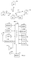
- FIG. 2 illustrates a block diagram of an electronic device, which may be subscriber equipment of a cellular radio system.
- the subscriber equipment may comprise an antenna 200, a transceiver 202, a controller 204, a sensor 206 for detecting characteristics of a user, components 208 to 220 for providing a user perceivable output quantity, a memory 222, a keypad or a keyboard 224 and a microphone 226.
- the sensor 206 for detecting characteristics of a user may be a fingerprint sensor, a palmprint sensor or the like. In general, the sensor may detect position-dependent properties of skin.
- the user perceivable output quantity may be provided by at least one of the following: a display 208, a camera 210, a light 212, a loudspeaker 214, a vibrational source 216, a clock 218, a backlight 220, etc. or any combination thereof.
- the antenna 200 transmits and receives signals, the destination or source of which is a base station of the radio system.
- the transmitter of the transceiver 202 may comprise a modulator, which can perform digital signal processing, and radio frequency parts, in which a signal can be multiplied and filtered so as to be transferred to a radio frequency determined by a carrier wave.
- the receiver of the transceiver 202 may transfer a received radio frequency signal to a baseband frequency and a demodulator of the receiver can transform an analog signal of the baseband frequency into a digital signal.
- the controller 204 may provide digital signal processing needed, typically implemented with a microprocessor, a signal processor or separate components and associated software. The controller 204 may also control the operation of the subscriber equipment.
- the fingerprint sensor functioning as a sensor 206 for detecting characteristics of a user can be used to detect a relief of a fingertip.
- the display 208 can be configured to display graphics and text.
- the camera 210 can be used to take a digital photo or video.
- the light 212 can be used as an electric torch and it may include at least one LED (Light Emitting Diode) or another source of optical radiation.
- the loudspeaker 214 may be a loudspeaker from which the user hears, for instance, the voice of the other user or any other sound associated with the data stored or received in the subscriber equipment.
- the microphone 226, in turn, can be an interface used for inputting the voice of the user transformed into an electrical form into the electronic device.
- the clock 218, which may be a part of the display, can be used to show the time for the user.
- the memory 222 is needed, for instance, for storing the fingerprint of the user or telephone numbers, calendar data and other user-specific data.
- the backlight 220 is meant to illuminate the display 208 and/or the keypad 224 to allow the user to see their indications also in the dark.
- the backlight 220 and the light 212 do not need to be separate but can also be combined.
- the vibrating alert of the vibrational source 216 may be used to arouse the user's attention with or without a ringing tone.
- the controller 204 may control all the components 202, 206 to 226.
- the electronic device is not necessarily subscriber equipment, and hence does not necessarily include the antenna 200 and the transceiver 202.
- the sensor 206 for detecting characteristics of a user, at least one component 208 to 220 for providing a user perceivable output quantity and the controller 204 are needed.
- the sensor 206 for detecting characteristics of a user may be a sensor for detecting characteristics of skin, such as a fingerprint sensor.
- the sensor may comprise an array or a matrix of pixels as a detector in order to form a digital image of the characterising object.
- the sensor with an array of pixels can also be called a strip or a sweep sensor because a finger is swept over the strip.
- the sensor with a matrix of pixels is also known as an area type of sensor or a touch type of sensor because the pixels cover an area corresponding to that of a fingertip. Hence, an image of a fingertip is formed without sweeping.
- Optical sensors take an optical image of a fingertip and they may additionally process the image to form an image of the fingerprint with an enhanced contrast between ridges and valleys.
- the ridges and valleys of a finger on the sensor change the capacitance between adjacent pixels.
- an image of the fingerprint can be obtained.
- Thermal capacity sensors measure heat emission from a fingertip. Usually a pixel receives more heat from a ridge than from a valley, and by measuring the temperature differences detected by the pixels, an image of the fingerprint can be synthesized.
- Electric field radiated from a fingertip can also be measured.
- An electric field sensor may feed the fingertip with a low-powered signal. The signal progresses through the finger back to the array or the matrix of the pixels of the sensor which measure the attenuation of the signal. Since the ridges have a different attenuation than the valleys, the measured two-dimensional distribution of the attenuation is a representation of the fingerprint.
- conductivity of a fingertip can be measured and an image of a fingerprint can be formed.
- a pressure-sensitive fingerprint sensor can be used.
- the sensor may form an image of a fingerprint based on the fact that a ridge exerts more pressure on a sensor than a valley.
- the two-dimensional distribution of the pressure corresponds to the fingerprint.
- an image of a fingertip can be formed using an ultrasound sensor.
- Images formed in any technique can be recorded and processed similarly in a digital form.
- any sensor detecting a characterized feature of a user can be used.
- a characteristic means a characterized feature of a user, which may be a relief of a certain part of skin, and more specifically the skin of a fingertip.
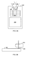
- Figure 3A shows an embodiment of a possible operation for controlling the electronic device 300 having a sensor 206 for detecting characteristics of a user.
- the characteristics of the user are read from a fingertip 302.
- the fingertip 302 is rotated in either direction around a normal of a surface of a sensor 206.
- the rotational center is marked with a dot on the fingernail.
- the initial position of the fingertip 302, when the detector first detects the fingertip 302, is illustrated using a continuous line, and the final position of the fingertip for this adjustment step is illustrated using a dashed line.
- the controller 204 includes an image processing program
- the controller 204 is capable of detecting the rotational movement of the fingerprint around the normal of the surface of the sensor 206.
- the resolution may be lower than in the actual fingerprint authentication operation which is used to verify a proper user. That speeds up the control.
- a piece of information on the rotational movement can be input from the sensor 206 to the controller 204.
- the scaling of a desired user perceivable output quantity of the electronic device can be controlled by the controller 204 as a function of the rotational movement detected by the sensor 206.
- Figure 3B shows the electronic device 300 from side in order to illustrate the direction of the normal n of the surface of the sensor 206 and the rotation of the finger around it.
- the user perceivable output quantity may be a user perceivable acoustic quantity, a user perceivable visual quantity or a user perceivable tactile quantity or the like.
- the user perceivable visual quantity may be a scene seen in the camera 210 and/or the display 208.
- the scene may be controlled and the magnification of the camera 210 may be the scaling parameter.
- the magnification of the camera 210 is increased or decreased by rotating a finger 302 in either direction on the sensor 206. For instance, by rotating the finger 302 clockwise around the normal of the surface of the sensor 206 may zoom in and rotating the finger 302 counter-clockwise may zoom out.
- the scaling operation is applied to the scene as a whole. Non-rotational movements of the finger may be used for other purposes and/or adjustments.
- magnification of the display 208 may be controlled.
- rotating the finger 302 clockwise around the normal of the surface of the sensor 206 may zoom in a document or an image in the display.
- Rotating the finger 302 counter-clockwise may zoom out the document or the image.
- the user perceivable visual quantity may be illumination provided by the backlight 220.
- the illumination strength, optical band (colour) or contrast may be the scaling parameters.
- illumination strength, optical band (colour) or contrast may be controlled by the controller 204.
- the illumination strength of each RGB (Red, Green, Blue) colour can also be controllable scaling parameters.
- the user perceivable visual quantity may also be illumination of the light 212, which may a filament lamp, halogen lamp, gas lamp, light-emitting diode, laser or the like.
- the illumination strength or optical band may be the scaling parameters.
- the illumination strength or the optical band may be controlled by the rotation of a finger.
- the time of a clock may be adjusted by turning a finger on the sensor 206.
- the user perceivable acoustic quantity may be sound or voice heard from the loudspeaker 214, or any other sound (such as "click” from depressible buttons or keys).
- the scaling may be applied to such user perceivable acoustic quantities as volume of the sound or voice which may be increased or decreased by the controller 204 according to the rotational movement detected by the sensor 206.
- a parameter of the user perceivable acoustic quantity to be scaled may also be a tone (i.e. frequency or acoustic band) of the sound or voice heard from the loudspeaker 214 which may be tuned by the controller 204 according to the rotation of a finger.
- the user perceivable tactile quantity may be a vibration of the electronic device.
- the scaling of the vibration means increasing or decreasing the vibration strength in whole band or at one or more vibrational bands (vibration frequencies) separately.
- the vibration strength may be changed by the controller 204 according to the rotation of a finger.
- Figure 4 shows another embodiment.
- the user perceivable quantity can be controlled by a length of time which is used in receiving the characteristics of a user by the sensor 206.
- the longer the user keeps his/her finger on the sensor 206 the more the user perceivable output quantity can be altered.
- a zoom of the camera 210 of the electronic device is to be changed.
- the user puts his/her finger 302 on the sensor 206 for detecting a fingerprint. If the user keeps his/her finger 302 on the sensor 206 for a short while, the magnification of the camera may increase (decrease). If the user keeps his/her finger 302 on the sensor 206 for a longer time, the magnification may decrease (increase) because after the magnification has reached its maximum, the magnification may start smoothly decreasing.
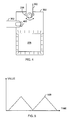
- This kind of behaviour is shown in Figure 5 .
- a value of the user perceivable output quantity 500 is in y-axis and time is in x-axis.
- the scale is arbitrary.
- magnification may suddenly drop to the minimum and start increasing, i.e. the control of the magnification may be cyclic.
- Figure 6 A value of the user perceivable output quantity 600 is in y-axis and time is in x-axis, both in an arbitrary scale.
- the illumination of the display 208 of the electronic device may be changed.
- the user puts his/her finger 302 on the sensor 206 for detecting a fingerprint. If the user keeps his/her finger 302 on the sensor 206 for a short while, the illumination may become brighter. If the user keeps his/her finger 302 on the sensor 206 for a longer time, the illumination may become darker because after the illumination has reached its maximum, the illumination may start smoothly decreasing. If the illumination is cyclic, the maximum illumination may suddenly drop to the minimum and start increasing again.
- the user perceivable output quantity of any component 208 to 220 may be controlled in a corresponding manner.
- the user may select the type of control of a user perceivable quantity.
- the user may press a button or a key 400 to input an input code determining a type of control of the user perceivable quantity.
- the type of control may include strengthening or weakening the user perceivable quantity, such as acoustic, visual or tactile quantity. That means that the direction of the control (such as illumination up or down) can be determined.
- the controller 204 may control the user perceivable output quantity of the electronic device according to the input code as a function of the length of the time in the receiving the characteristics of a user.
- the simple code input by depressing the button 400 may determine that the illumination is to be increased and the length of time in the receiving the characteristics of a user may determine how much the illumination is to be increased. If the button 400 is not pressed, it may mean a code for decreasing the illumination as a function of the time the user keeps his/her finger on the sensor.
- the type of control by an input key of the electronic device may be determined such that one kind of control of the user perceivable output quantity is active without pressing the input key and a different kind of control of the user perceivable output quantity is activated by pressing the key.
- Figure 7 shows an example similar to Figure 4 .
- the difference in this example is that all types of the control have their own buttons 500, 502.
- the type of control can be determined by an activation of, for example, a pair of input keys 500, 502 of the electronic device.
- a first input key 500 may activate one kind of control of the user perceivable output quantity and a second input key 502 may activate a different kind of control of the user perceivable output quantity.
- a button 500 is pressed.
- a button 502 is pressed.
- the type of control can be determined based on a number of times a button is tapped.
- the sensor can be built on a switch 800 as shown in Figure 8 .
- the sensor 206 can first be tapped to activate the sensor 206 and then the sensor 206 can be used to control the user perceivable quantity.
- the sensor 206 moves abruptly in the vertical direction and that makes the switch 800 change its state.
- the switching of the switch 800 is recognized by the controller 204, which activates the sensor 206.
- the controller 204 may also perform context recognition and monitor the user activity.
- the user perceivable output quantity to be controlled can be selected according to the context. For example, if the electronic device is subscriber equipment and the user selects the use of the camera of the electronic device, the controller may detect the context: use of camera. Based on this recognition, the controller may select visual output quantity for the sensor 206 to be controlled. For instance, the sensor 206 may be used to control the zoom operation of the camera (and the display).
- the user may be listening to radio or some recording with his/her mobile phone when his/her mobile phone rings. The user may listen to the voice of the person who calls him and the radio or the recording at the same time, but the user may turn downwards the volume of the radio or the recording by rotating his/her finger on the fingerprint sensor.
- the turning angle of the characteristic part of the user on the sensor may determine the change in the scaling of the user perceivable output quantity.
- the coordinate system to determine the angle may be relative or fixed with respect to the structure of the sensor.
- an initial position of the characteristic part of the user is first detected and the initial position can be considered the origin at the beginning of each adjustment.
- the origin is variable or relative.
- the angle is measured and the user perceivable output quantity is controlled as a function of the rotation (i.e. angle) of the characteristic part of the user.
- a predetermined position of the characteristic part of the user in relation to the structure of the sensor is considered the origin of the rotation. If the characteristic part of the user is put on the sensor in a position different from the origin, the sensor may detect the angle between the origin and the observed position. Hence, in this solution the initial position does not each time determine a new origin, but the origin is fixed or constant. However, changing the strength of the user perceivable output quantity still depends on the detected rotation of the characteristic part of the user on the sensor.
- Figure 9 shows a flow chart of a method of controlling an electronic device having a sensor for detecting characteristics of a user.
- step 900 rotational movement of the characteristics of a user around a normal of a surface of a sensor detecting characteristics of user is detected.
- step 902 the scaling of a user perceivable output quantity of the electronic device is controlled as a function of the rotational movement detected by the sensor.
- Figure 10 shows a flow chart of another method of controlling an electronic device having a sensor for detecting characteristics of a user.
- a sensor for detecting characteristics of a user receives characteristics of a user.
- a length of time relating to receiving the characteristics of a user is determined.
- the scaling of the user perceivable output quantity of the electronic device is controlled as a function of the length of the time relating to receiving the characteristics of the user.
- the implementation of the solution described in the application can be accomplished, for example, by means of specific equipment providing the required operations, such as an application-specific integrated circuit (ASIC), or separate logic components.
- the implementation may also be accomplished, for example, by means of software, the controller 204 comprising enough memory and a microprocessor, where the operations of the method described above are carried out in the form of software.
- a computer program product may en-code a computer program of instructions for executing a computer process for controlling an electronic device having a sensor for detecting characteristics of a user according to the methods described in Figures 9 and 10 .
- a computer program can be distributed in a distribution medium readable by a computer.
- the computer program of instructions can be encoded for executing the computer process for executing a computer process for controlling an electronic device having a sensor for detecting characteristics of a user according to the methods described in Figures 9 and 10 .
- the distribution medium may comprise a computer readable medium, a program storage medium, a record medium, a computer readable memory, a computer readable software distribution package, a computer readable signal, a computer readable telecommunications signal, a computer readable compressed software package or any combination thereof.
Landscapes
- Engineering & Computer Science (AREA)
- Theoretical Computer Science (AREA)
- General Engineering & Computer Science (AREA)
- Human Computer Interaction (AREA)
- Physics & Mathematics (AREA)
- General Physics & Mathematics (AREA)
- Computer Hardware Design (AREA)
- Multimedia (AREA)
- User Interface Of Digital Computer (AREA)
- Telephone Function (AREA)
- Image Input (AREA)
- Selective Calling Equipment (AREA)
- Measurement Of The Respiration, Hearing Ability, Form, And Blood Characteristics Of Living Organisms (AREA)
- Position Input By Displaying (AREA)
- Electric Clocks (AREA)
Applications Claiming Priority (2)
| Application Number | Priority Date | Filing Date | Title |
|---|---|---|---|
| PCT/FI2005/050235 WO2006136644A1 (en) | 2005-06-23 | 2005-06-23 | Method and program of controlling electronic device, electronic device and subscriber equipment |
| EP05757908A EP1894143B1 (de) | 2005-06-23 | 2005-06-23 | Verfahren und programm zum steuern eines elektronischen geräts, elektronisches gerät und teilnehmerapparat |
Related Parent Applications (1)
| Application Number | Title | Priority Date | Filing Date |
|---|---|---|---|
| EP05757908.8 Division | 2005-06-23 |
Publications (2)
| Publication Number | Publication Date |
|---|---|
| EP2249285A1 true EP2249285A1 (de) | 2010-11-10 |
| EP2249285B1 EP2249285B1 (de) | 2012-06-20 |
Family
ID=37570141
Family Applications (2)
| Application Number | Title | Priority Date | Filing Date |
|---|---|---|---|
| EP05757908A Expired - Lifetime EP1894143B1 (de) | 2005-06-23 | 2005-06-23 | Verfahren und programm zum steuern eines elektronischen geräts, elektronisches gerät und teilnehmerapparat |
| EP10173362A Expired - Lifetime EP2249285B1 (de) | 2005-06-23 | 2005-06-23 | Verfahren und Programm zum Steuern des Abonnentengeräts und Abonnentengerät |
Family Applications Before (1)
| Application Number | Title | Priority Date | Filing Date |
|---|---|---|---|
| EP05757908A Expired - Lifetime EP1894143B1 (de) | 2005-06-23 | 2005-06-23 | Verfahren und programm zum steuern eines elektronischen geräts, elektronisches gerät und teilnehmerapparat |
Country Status (6)
| Country | Link |
|---|---|
| US (1) | US9152840B2 (de) |
| EP (2) | EP1894143B1 (de) |
| CN (1) | CN101228534B (de) |
| AT (1) | ATE484035T1 (de) |
| DE (1) | DE602005024057D1 (de) |
| WO (1) | WO2006136644A1 (de) |
Families Citing this family (12)
| Publication number | Priority date | Publication date | Assignee | Title |
|---|---|---|---|---|
| US7697827B2 (en) | 2005-10-17 | 2010-04-13 | Konicek Jeffrey C | User-friendlier interfaces for a camera |
| JP4609543B2 (ja) * | 2008-07-25 | 2011-01-12 | ソニー株式会社 | 情報処理装置及び情報処理方法 |
| GB2496080A (en) * | 2010-07-29 | 2013-05-01 | Ultra Scan Corp | Device and method of controlling a computer using centroids |
| US20140118267A1 (en) * | 2012-10-31 | 2014-05-01 | Vishal Thomas | Code Entry System |
| US9189108B2 (en) * | 2013-08-21 | 2015-11-17 | Qualcomm Incorporated | Ultrasound multi-zone hovering system |
| US20150078586A1 (en) * | 2013-09-16 | 2015-03-19 | Amazon Technologies, Inc. | User input with fingerprint sensor |
| US9721141B2 (en) * | 2014-10-30 | 2017-08-01 | Polar Electro Oy | Wrist-worn apparatus control with fingerprint data |
| USD776664S1 (en) * | 2015-05-20 | 2017-01-17 | Chaya Coleena Hendrick | Smart card |
| CN105159571A (zh) * | 2015-07-07 | 2015-12-16 | 努比亚技术有限公司 | 控制页面滑动的方法及移动终端 |
| CN105138132A (zh) * | 2015-08-31 | 2015-12-09 | 宇龙计算机通信科技(深圳)有限公司 | 基于指纹识别的触控方法、装置及终端 |
| DE102016119844B4 (de) * | 2016-10-18 | 2024-07-25 | Preh Gmbh | Fingerabdrucksensor mit Rotationsgestenfunktionalität |
| US10339361B2 (en) * | 2017-03-23 | 2019-07-02 | International Business Machines Corporation | Composite fingerprint authenticator |
Citations (2)
| Publication number | Priority date | Publication date | Assignee | Title |
|---|---|---|---|---|
| US4511781A (en) * | 1981-02-23 | 1985-04-16 | Rangaire Corporation | Induction cook-top system and control |
| US20050041885A1 (en) * | 2003-08-22 | 2005-02-24 | Russo Anthony P. | System for and method of generating rotational inputs |
Family Cites Families (23)
| Publication number | Priority date | Publication date | Assignee | Title |
|---|---|---|---|---|
| JP3475419B2 (ja) * | 1995-10-11 | 2003-12-08 | ソニー株式会社 | テレビジョン受像機 |
| US5825352A (en) * | 1996-01-04 | 1998-10-20 | Logitech, Inc. | Multiple fingers contact sensing method for emulating mouse buttons and mouse operations on a touch sensor pad |
| US5859420A (en) * | 1996-02-12 | 1999-01-12 | Dew Engineering And Development Limited | Optical imaging device |
| JP3280559B2 (ja) * | 1996-02-20 | 2002-05-13 | シャープ株式会社 | ジョグダイアルの模擬入力装置 |
| US6057540A (en) * | 1998-04-30 | 2000-05-02 | Hewlett-Packard Co | Mouseless optical and position translation type screen pointer control for a computer system |
| US6324310B1 (en) * | 1998-06-02 | 2001-11-27 | Digital Persona, Inc. | Method and apparatus for scanning a fingerprint using a linear sensor |
| DE19920162C2 (de) | 1999-04-28 | 2001-09-27 | Hertz Inst Heinrich | Verfahren zur Steuerung von Geräten mittels einer Fernbedienung |
| US20030006956A1 (en) * | 1999-05-24 | 2003-01-09 | Charles Yimin Wu | Data entry device recording input in two dimensions |
| US7054470B2 (en) * | 1999-12-02 | 2006-05-30 | International Business Machines Corporation | System and method for distortion characterization in fingerprint and palm-print image sequences and using this distortion as a behavioral biometrics |
| US6943778B1 (en) * | 2000-11-20 | 2005-09-13 | Nokia Corporation | Touch screen input technique |
| US6677929B2 (en) * | 2001-03-21 | 2004-01-13 | Agilent Technologies, Inc. | Optical pseudo trackball controls the operation of an appliance or machine |
| US20030035568A1 (en) * | 2001-08-20 | 2003-02-20 | Mitev Mitko G. | User interface including multifunction fingerprint roller and computer including the same |
| US7345671B2 (en) * | 2001-10-22 | 2008-03-18 | Apple Inc. | Method and apparatus for use of rotational user inputs |
| US7312785B2 (en) * | 2001-10-22 | 2007-12-25 | Apple Inc. | Method and apparatus for accelerated scrolling |
| JP4522043B2 (ja) * | 2002-09-06 | 2010-08-11 | セイコーエプソン株式会社 | 情報装置及び表示制御方法 |
| AU2003296487A1 (en) | 2002-12-09 | 2004-06-30 | Adam Kaplan | Method and apparatus for user interface |
| NO318169B1 (no) | 2002-12-18 | 2005-02-14 | Svein Mathiassen | Anordning for fjernkontroll og autentisering |
| EP1437677A1 (de) * | 2002-12-30 | 2004-07-14 | Nokia Corporation | Optische Benutzerschnittstelle zum Steuern einer tragbaren elektrischen Vorrichtung |
| US7406331B2 (en) * | 2003-06-17 | 2008-07-29 | Sony Ericsson Mobile Communications Ab | Use of multi-function switches for camera zoom functionality on a mobile phone |
| US7499040B2 (en) * | 2003-08-18 | 2009-03-03 | Apple Inc. | Movable touch pad with added functionality |
| US8531392B2 (en) * | 2004-08-04 | 2013-09-10 | Interlink Electronics, Inc. | Multifunctional scroll sensor |
| US7450111B2 (en) * | 2004-10-27 | 2008-11-11 | Nokia Corporation | Key functionality for communication terminal |
| US20100188268A1 (en) * | 2006-09-01 | 2010-07-29 | Nokia Corporation | Touchpad |
-
2005
- 2005-06-23 EP EP05757908A patent/EP1894143B1/de not_active Expired - Lifetime
- 2005-06-23 DE DE602005024057T patent/DE602005024057D1/de not_active Expired - Lifetime
- 2005-06-23 EP EP10173362A patent/EP2249285B1/de not_active Expired - Lifetime
- 2005-06-23 AT AT05757908T patent/ATE484035T1/de not_active IP Right Cessation
- 2005-06-23 WO PCT/FI2005/050235 patent/WO2006136644A1/en not_active Ceased
- 2005-06-23 US US11/922,647 patent/US9152840B2/en not_active Expired - Fee Related
- 2005-06-23 CN CN200580051142XA patent/CN101228534B/zh not_active Expired - Fee Related
Patent Citations (2)
| Publication number | Priority date | Publication date | Assignee | Title |
|---|---|---|---|---|
| US4511781A (en) * | 1981-02-23 | 1985-04-16 | Rangaire Corporation | Induction cook-top system and control |
| US20050041885A1 (en) * | 2003-08-22 | 2005-02-24 | Russo Anthony P. | System for and method of generating rotational inputs |
Also Published As
| Publication number | Publication date |
|---|---|
| ATE484035T1 (de) | 2010-10-15 |
| CN101228534B (zh) | 2011-04-20 |
| CN101228534A (zh) | 2008-07-23 |
| WO2006136644A1 (en) | 2006-12-28 |
| US9152840B2 (en) | 2015-10-06 |
| DE602005024057D1 (de) | 2010-11-18 |
| US20090243790A1 (en) | 2009-10-01 |
| EP2249285B1 (de) | 2012-06-20 |
| EP1894143B1 (de) | 2010-10-06 |
| EP1894143A1 (de) | 2008-03-05 |
Similar Documents
| Publication | Publication Date | Title |
|---|---|---|
| EP1894143B1 (de) | Verfahren und programm zum steuern eines elektronischen geräts, elektronisches gerät und teilnehmerapparat | |
| EP1986404B1 (de) | Mobiles Kommunikationsendgerät mit Funktion zur Verhinderung von Tasteneingabefehlern und Verfahren dafür | |
| US9658767B2 (en) | Information processing device | |
| US7176905B2 (en) | Electronic device having an image-based data input system | |
| US9342682B2 (en) | Portable electronic device | |
| US8493334B2 (en) | Input device, storage medium, information input method, and electronic apparatus | |
| US20110275412A1 (en) | Automatic gain control based on detected pressure | |
| US20020167489A1 (en) | Pushbutton optical screen pointing device | |
| CN111338725A (zh) | 界面布局方法及相关产品 | |
| US20170285760A1 (en) | Apparatus for projecting image and method for operating same | |
| CN110276328B (zh) | 指纹识别方法及相关产品 | |
| CN109634438B (zh) | 一种输入法的控制方法及终端设备 | |
| US20060221935A1 (en) | Method and apparatus for representing communication attributes | |
| CN112400309A (zh) | 消息提示方法及相关产品 | |
| CN110516495B (zh) | 一种扫码方法和移动终端 | |
| CN112400305B (zh) | 消息提示方法及相关产品 | |
| JP2004334738A (ja) | 入力装置 | |
| US7961176B2 (en) | Input apparatus and method using optical sensing, and portable terminal using the same | |
| US20190129609A1 (en) | Electronic apparatus | |
| US20190258843A1 (en) | Electronic device and control method | |
| KR100800854B1 (ko) | 이동통신 단말기의 홀로그램 메뉴 생성 장치 및 방법 | |
| CN111383544A (zh) | 一种显示屏、终端及显示方法 | |
| CN115995101A (zh) | 虚拟指纹的生成方法、系统、装置及设备 | |
| JP4925628B2 (ja) | 携帯電話装置及び携帯電話装置の制御方法 | |
| JP5657481B2 (ja) | 携帯電話装置及び携帯電話装置の制御方法 |
Legal Events
| Date | Code | Title | Description |
|---|---|---|---|
| PUAI | Public reference made under article 153(3) epc to a published international application that has entered the european phase |
Free format text: ORIGINAL CODE: 0009012 |
|
| AC | Divisional application: reference to earlier application |
Ref document number: 1894143 Country of ref document: EP Kind code of ref document: P |
|
| AK | Designated contracting states |
Kind code of ref document: A1 Designated state(s): AT BE BG CH CY CZ DE DK EE ES FI FR GB GR HU IE IS IT LI LT LU MC NL PL PT RO SE SI SK TR |
|
| 17P | Request for examination filed |
Effective date: 20110510 |
|
| 17Q | First examination report despatched |
Effective date: 20110601 |
|
| GRAP | Despatch of communication of intention to grant a patent |
Free format text: ORIGINAL CODE: EPIDOSNIGR1 |
|
| RIC1 | Information provided on ipc code assigned before grant |
Ipc: G06F 3/01 20060101ALI20111212BHEP Ipc: G06K 9/00 20060101AFI20111212BHEP |
|
| GRAS | Grant fee paid |
Free format text: ORIGINAL CODE: EPIDOSNIGR3 |
|
| GRAA | (expected) grant |
Free format text: ORIGINAL CODE: 0009210 |
|
| AC | Divisional application: reference to earlier application |
Ref document number: 1894143 Country of ref document: EP Kind code of ref document: P |
|
| AK | Designated contracting states |
Kind code of ref document: B1 Designated state(s): AT BE BG CH CY CZ DE DK EE ES FI FR GB GR HU IE IS IT LI LT LU MC NL PL PT RO SE SI SK TR |
|
| REG | Reference to a national code |
Ref country code: GB Ref legal event code: FG4D |
|
| REG | Reference to a national code |
Ref country code: CH Ref legal event code: EP |
|
| REG | Reference to a national code |
Ref country code: AT Ref legal event code: REF Ref document number: 563405 Country of ref document: AT Kind code of ref document: T Effective date: 20120715 |
|
| REG | Reference to a national code |
Ref country code: IE Ref legal event code: FG4D |
|
| REG | Reference to a national code |
Ref country code: NL Ref legal event code: T3 |
|
| REG | Reference to a national code |
Ref country code: DE Ref legal event code: R096 Ref document number: 602005034898 Country of ref document: DE Effective date: 20120816 |
|
| PG25 | Lapsed in a contracting state [announced via postgrant information from national office to epo] |
Ref country code: LT Free format text: LAPSE BECAUSE OF FAILURE TO SUBMIT A TRANSLATION OF THE DESCRIPTION OR TO PAY THE FEE WITHIN THE PRESCRIBED TIME-LIMIT Effective date: 20120620 Ref country code: SE Free format text: LAPSE BECAUSE OF FAILURE TO SUBMIT A TRANSLATION OF THE DESCRIPTION OR TO PAY THE FEE WITHIN THE PRESCRIBED TIME-LIMIT Effective date: 20120620 Ref country code: FI Free format text: LAPSE BECAUSE OF FAILURE TO SUBMIT A TRANSLATION OF THE DESCRIPTION OR TO PAY THE FEE WITHIN THE PRESCRIBED TIME-LIMIT Effective date: 20120620 |
|
| REG | Reference to a national code |
Ref country code: AT Ref legal event code: MK05 Ref document number: 563405 Country of ref document: AT Kind code of ref document: T Effective date: 20120620 |
|
| REG | Reference to a national code |
Ref country code: LT Ref legal event code: MG4D Effective date: 20120620 |
|
| PG25 | Lapsed in a contracting state [announced via postgrant information from national office to epo] |
Ref country code: SI Free format text: LAPSE BECAUSE OF FAILURE TO SUBMIT A TRANSLATION OF THE DESCRIPTION OR TO PAY THE FEE WITHIN THE PRESCRIBED TIME-LIMIT Effective date: 20120620 Ref country code: GR Free format text: LAPSE BECAUSE OF FAILURE TO SUBMIT A TRANSLATION OF THE DESCRIPTION OR TO PAY THE FEE WITHIN THE PRESCRIBED TIME-LIMIT Effective date: 20120921 |
|
| PG25 | Lapsed in a contracting state [announced via postgrant information from national office to epo] |
Ref country code: MC Free format text: LAPSE BECAUSE OF NON-PAYMENT OF DUE FEES Effective date: 20120630 Ref country code: RO Free format text: LAPSE BECAUSE OF FAILURE TO SUBMIT A TRANSLATION OF THE DESCRIPTION OR TO PAY THE FEE WITHIN THE PRESCRIBED TIME-LIMIT Effective date: 20120620 Ref country code: IS Free format text: LAPSE BECAUSE OF FAILURE TO SUBMIT A TRANSLATION OF THE DESCRIPTION OR TO PAY THE FEE WITHIN THE PRESCRIBED TIME-LIMIT Effective date: 20121020 Ref country code: BE Free format text: LAPSE BECAUSE OF FAILURE TO SUBMIT A TRANSLATION OF THE DESCRIPTION OR TO PAY THE FEE WITHIN THE PRESCRIBED TIME-LIMIT Effective date: 20120620 Ref country code: CY Free format text: LAPSE BECAUSE OF FAILURE TO SUBMIT A TRANSLATION OF THE DESCRIPTION OR TO PAY THE FEE WITHIN THE PRESCRIBED TIME-LIMIT Effective date: 20120620 Ref country code: EE Free format text: LAPSE BECAUSE OF FAILURE TO SUBMIT A TRANSLATION OF THE DESCRIPTION OR TO PAY THE FEE WITHIN THE PRESCRIBED TIME-LIMIT Effective date: 20120620 Ref country code: AT Free format text: LAPSE BECAUSE OF FAILURE TO SUBMIT A TRANSLATION OF THE DESCRIPTION OR TO PAY THE FEE WITHIN THE PRESCRIBED TIME-LIMIT Effective date: 20120620 Ref country code: SK Free format text: LAPSE BECAUSE OF FAILURE TO SUBMIT A TRANSLATION OF THE DESCRIPTION OR TO PAY THE FEE WITHIN THE PRESCRIBED TIME-LIMIT Effective date: 20120620 Ref country code: CZ Free format text: LAPSE BECAUSE OF FAILURE TO SUBMIT A TRANSLATION OF THE DESCRIPTION OR TO PAY THE FEE WITHIN THE PRESCRIBED TIME-LIMIT Effective date: 20120620 |
|
| REG | Reference to a national code |
Ref country code: CH Ref legal event code: PL |
|
| REG | Reference to a national code |
Ref country code: CH Ref legal event code: PL |
|
| PG25 | Lapsed in a contracting state [announced via postgrant information from national office to epo] |
Ref country code: PT Free format text: LAPSE BECAUSE OF FAILURE TO SUBMIT A TRANSLATION OF THE DESCRIPTION OR TO PAY THE FEE WITHIN THE PRESCRIBED TIME-LIMIT Effective date: 20121022 Ref country code: IT Free format text: LAPSE BECAUSE OF FAILURE TO SUBMIT A TRANSLATION OF THE DESCRIPTION OR TO PAY THE FEE WITHIN THE PRESCRIBED TIME-LIMIT Effective date: 20120620 Ref country code: PL Free format text: LAPSE BECAUSE OF FAILURE TO SUBMIT A TRANSLATION OF THE DESCRIPTION OR TO PAY THE FEE WITHIN THE PRESCRIBED TIME-LIMIT Effective date: 20120620 |
|
| REG | Reference to a national code |
Ref country code: IE Ref legal event code: MM4A |
|
| PLBE | No opposition filed within time limit |
Free format text: ORIGINAL CODE: 0009261 |
|
| STAA | Information on the status of an ep patent application or granted ep patent |
Free format text: STATUS: NO OPPOSITION FILED WITHIN TIME LIMIT |
|
| PG25 | Lapsed in a contracting state [announced via postgrant information from national office to epo] |
Ref country code: LI Free format text: LAPSE BECAUSE OF NON-PAYMENT OF DUE FEES Effective date: 20120630 Ref country code: ES Free format text: LAPSE BECAUSE OF FAILURE TO SUBMIT A TRANSLATION OF THE DESCRIPTION OR TO PAY THE FEE WITHIN THE PRESCRIBED TIME-LIMIT Effective date: 20121001 Ref country code: IE Free format text: LAPSE BECAUSE OF NON-PAYMENT OF DUE FEES Effective date: 20120623 Ref country code: CH Free format text: LAPSE BECAUSE OF NON-PAYMENT OF DUE FEES Effective date: 20120630 Ref country code: DK Free format text: LAPSE BECAUSE OF FAILURE TO SUBMIT A TRANSLATION OF THE DESCRIPTION OR TO PAY THE FEE WITHIN THE PRESCRIBED TIME-LIMIT Effective date: 20120620 |
|
| 26N | No opposition filed |
Effective date: 20130321 |
|
| REG | Reference to a national code |
Ref country code: DE Ref legal event code: R097 Ref document number: 602005034898 Country of ref document: DE Effective date: 20130321 |
|
| PG25 | Lapsed in a contracting state [announced via postgrant information from national office to epo] |
Ref country code: BG Free format text: LAPSE BECAUSE OF FAILURE TO SUBMIT A TRANSLATION OF THE DESCRIPTION OR TO PAY THE FEE WITHIN THE PRESCRIBED TIME-LIMIT Effective date: 20120920 |
|
| PG25 | Lapsed in a contracting state [announced via postgrant information from national office to epo] |
Ref country code: TR Free format text: LAPSE BECAUSE OF FAILURE TO SUBMIT A TRANSLATION OF THE DESCRIPTION OR TO PAY THE FEE WITHIN THE PRESCRIBED TIME-LIMIT Effective date: 20120620 |
|
| PG25 | Lapsed in a contracting state [announced via postgrant information from national office to epo] |
Ref country code: LU Free format text: LAPSE BECAUSE OF NON-PAYMENT OF DUE FEES Effective date: 20120623 |
|
| PG25 | Lapsed in a contracting state [announced via postgrant information from national office to epo] |
Ref country code: HU Free format text: LAPSE BECAUSE OF FAILURE TO SUBMIT A TRANSLATION OF THE DESCRIPTION OR TO PAY THE FEE WITHIN THE PRESCRIBED TIME-LIMIT Effective date: 20050623 |
|
| REG | Reference to a national code |
Ref country code: GB Ref legal event code: 732E Free format text: REGISTERED BETWEEN 20150910 AND 20150916 |
|
| REG | Reference to a national code |
Ref country code: DE Ref legal event code: R081 Ref document number: 602005034898 Country of ref document: DE Owner name: NOKIA TECHNOLOGIES OY, FI Free format text: FORMER OWNER: NOKIA CORP., 02610 ESPOO, FI |
|
| REG | Reference to a national code |
Ref country code: NL Ref legal event code: PD Owner name: NOKIA TECHNOLOGIES OY; FI Free format text: DETAILS ASSIGNMENT: VERANDERING VAN EIGENAAR(S), OVERDRACHT; FORMER OWNER NAME: NOKIA CORPORATION Effective date: 20151111 |
|
| REG | Reference to a national code |
Ref country code: FR Ref legal event code: PLFP Year of fee payment: 12 |
|
| REG | Reference to a national code |
Ref country code: FR Ref legal event code: TP Owner name: NOKIA TECHNOLOGIES OY, FI Effective date: 20170109 |
|
| REG | Reference to a national code |
Ref country code: FR Ref legal event code: PLFP Year of fee payment: 13 |
|
| REG | Reference to a national code |
Ref country code: FR Ref legal event code: PLFP Year of fee payment: 14 |
|
| REG | Reference to a national code |
Ref country code: DE Ref legal event code: R079 Ref document number: 602005034898 Country of ref document: DE Free format text: PREVIOUS MAIN CLASS: G06K0009000000 Ipc: G06V0010000000 |
|
| PGFP | Annual fee paid to national office [announced via postgrant information from national office to epo] |
Ref country code: NL Payment date: 20220513 Year of fee payment: 18 |
|
| PGFP | Annual fee paid to national office [announced via postgrant information from national office to epo] |
Ref country code: GB Payment date: 20220506 Year of fee payment: 18 Ref country code: FR Payment date: 20220510 Year of fee payment: 18 Ref country code: DE Payment date: 20220505 Year of fee payment: 18 |
|
| REG | Reference to a national code |
Ref country code: DE Ref legal event code: R119 Ref document number: 602005034898 Country of ref document: DE |
|
| REG | Reference to a national code |
Ref country code: NL Ref legal event code: MM Effective date: 20230701 |
|
| GBPC | Gb: european patent ceased through non-payment of renewal fee |
Effective date: 20230623 |
|
| PG25 | Lapsed in a contracting state [announced via postgrant information from national office to epo] |
Ref country code: NL Free format text: LAPSE BECAUSE OF NON-PAYMENT OF DUE FEES Effective date: 20230701 |
|
| PG25 | Lapsed in a contracting state [announced via postgrant information from national office to epo] |
Ref country code: DE Free format text: LAPSE BECAUSE OF NON-PAYMENT OF DUE FEES Effective date: 20240103 Ref country code: GB Free format text: LAPSE BECAUSE OF NON-PAYMENT OF DUE FEES Effective date: 20230623 |
|
| PG25 | Lapsed in a contracting state [announced via postgrant information from national office to epo] |
Ref country code: FR Free format text: LAPSE BECAUSE OF NON-PAYMENT OF DUE FEES Effective date: 20230630 |