EP2249340A1 - Plattenlaufwerkanordnung - Google Patents
Plattenlaufwerkanordnung Download PDFInfo
- Publication number
- EP2249340A1 EP2249340A1 EP08776913A EP08776913A EP2249340A1 EP 2249340 A1 EP2249340 A1 EP 2249340A1 EP 08776913 A EP08776913 A EP 08776913A EP 08776913 A EP08776913 A EP 08776913A EP 2249340 A1 EP2249340 A1 EP 2249340A1
- Authority
- EP
- European Patent Office
- Prior art keywords
- disc
- sliding
- connecting member
- contacting
- contacting pad
- Prior art date
- Legal status (The legal status is an assumption and is not a legal conclusion. Google has not performed a legal analysis and makes no representation as to the accuracy of the status listed.)
- Withdrawn
Links
- 238000000034 method Methods 0.000 abstract description 7
- 238000005516 engineering process Methods 0.000 abstract description 4
- 230000008878 coupling Effects 0.000 abstract 2
- 238000010168 coupling process Methods 0.000 abstract 2
- 238000005859 coupling reaction Methods 0.000 abstract 2
- 238000010586 diagram Methods 0.000 description 99
- 238000003780 insertion Methods 0.000 description 8
- 230000037431 insertion Effects 0.000 description 8
- 238000004519 manufacturing process Methods 0.000 description 6
- 230000000694 effects Effects 0.000 description 2
- 238000000926 separation method Methods 0.000 description 1
Images







Classifications
-
- G—PHYSICS
- G11—INFORMATION STORAGE
- G11B—INFORMATION STORAGE BASED ON RELATIVE MOVEMENT BETWEEN RECORD CARRIER AND TRANSDUCER
- G11B17/00—Guiding record carriers not specifically of filamentary or web form, or of supports therefor
- G11B17/02—Details
- G11B17/04—Feeding or guiding single record carrier to or from transducer unit
- G11B17/05—Feeding or guiding single record carrier to or from transducer unit specially adapted for discs not contained within cartridges
- G11B17/051—Direct insertion, i.e. without external loading means
- G11B17/0515—Direct insertion, i.e. without external loading means adapted for discs of different sizes
Definitions
- the present invention relates to a disc drive device having a slot-in loading mechanism
- a disc drive device records data on a disc such as CD or DVD, and reads data from a disc utilizing a disc drive built in the device.
- An example of inserting the disc into the device includes the slot-in system.
- the slot-in system when the disc is inserted in a slot (disc insertion slot) provided on the side surface etc. of the disc drive device and gently pressed, the disc is automatically transferred into the device by rollers equipped in the device.
- two types of discs having different diameters, 8cm and 12cm are inserted into the same disc insertion slot by the same process.
- it is required to precisely place the disc on a predetermined position in the device. Therefore, in the case of the slot-in system, it is essential to precisely place the inserted disc on the predetermined position, where the disc can be driven, in response to its size.
- Japanese Unexamined Patent Application Publication No. 2006-302384 discloses the invention to reduce the production cost and to implement the above function.
- Japanese Unexamined Patent Application Publication No. 2006-302384 discloses the invention to reduce the production cost and to implement the above function.
- the invention includes a disc stopper receiving an inserted disc and controlling a distance of movement in a direction of insertion, a select arm contacting the disc in different positions depending on a size of the inserted disc, a spring biasing the select arm at a predetermined degree, a stopper arm connecting the disc stopper and the select arm, and a spring biasing the select arm at a predetermined degree.
- the inserted disc is precisely placed on a predetermined position.
- Japanese Unexamined Patent Application Publication No. 2006-302384 the above function is implemented mainly by two springs and three other components, and causes the need for many components. Therefore, this is inconvenient in terms of space-saving in the disc drive device, and for minimizing the size of the device.
- the present invention provides a disc drive device that can reduce the production cost, and has a function of precisely placing the inserted disc on the predetermined position, where the disc can be driven, according to its size by the slot-in system with a smaller number of components compared with the conventional technology.
- a disk drive device comprising a contacting pad, receiving the disc in a different position depending on the size of the inserted disc, a connecting member, rotationally moving in a different trajectory and in a different location in response to the position of the contacting pad when rotationally moving upon the retraction of the disc, and a spring, biasing the connecting member to a predetermined degree.
- a first aspect of the invention is a disc drive device capable of distinguishing discs of different diameters, and of loading the discs onto respective proper positions using a slot-in system, comprising a first driving unit for retraction, retracting the discs of each respective diameter in an inward direction of the device, a contacting pad, contacting with an edge of the disc retracted by the driving unit for retraction at different points depending on the disc diameter, and sliding in response to the retraction of the disc in a sliding position depending on a contacting point, a shifter, sliding in a direction of retracting the disc, and a connecting member, sliding in response to variations of the sliding position of the contacting pad, and rotationally moving in response to the sliding of the contacting pad, wherein the connecting member comprises a latching protrusion/a protrusion with a latch function, rotationally moving in a different trajectory in response to the sliding position of the contacting pad, the shifter comprises a guiding groove for latching protrusion, into which the latching protrusion is inserted,
- a second aspect of the invention is the disc drive device based on the first aspect, wherein the connecting member also rotationally moves in response to the sliding of the shifter in the direction of retracting the disc, and the contacting pad also slides in response to the rotational movement of the connecting member in response to the sliding of the shifter in the direction of retracting the disc, thereby being non-contact with the disc.
- a third aspect of the invention is the disc drive device based on the first or second aspect, further comprising a biasing spring, biasing the sliding connecting member to return to an initial position.
- a fourth aspect of the invention is the disc drive device based on any one of the first to third aspects, comprising a guiding member, including a plurality of sliding grooves to slide the contacting pad in response to the retraction of the disc, wherein the contacting pad further comprises a plurality of sliding protrusions inserted into the sliding grooves, and timings of starting movements between the plurality of sliding protrusions are determined in response to the contacting points of the contacting pad with the disc, and the sliding position of the sliding contacting pad is determined in response to the timings of starting movements between the plurality of sliding protrusions.
- a fifth aspect of the invention is the disc drive device based on any one of the first to fourth aspects, wherein the connecting member comprises a protrusion for ejecting shifter, rotationally moving in different trajectory in response to the sliding position of the contacting pad, and the shifter comprises two portions for ejection, respectively contacting with the protrusion for ejecting shifter, rotationally moving in a different trajectory.
- the disc drive device of the present invention it is possible to precisely place the inserted disc on the predetermined position, where the disc can be driven, in response to its size by the slot-in system whilst reduced production cost and with smaller number of components compared to the conventional technology. As a result, it is possible to keep prices down and to save space in the device, thereby downsizing the production.
- the 'contacting pad' which receives the inserted disc, and slides in a direction of insertion, thereby controlling a movement distance of the disc, slides in a different position in response to a diameter of the disc.
- the other components operate differently in response to the sliding position of the contacting pad, and by a linkage of the operations, the 12cm in diameter and 8cm in diameter discs are precisely placed at a predetermined position, respectively.
- the disc drive device of the embodiment comprises a 'first driving unit for retraction' (1401), a 'contacting pad' (1402), a 'connecting member' (1403), and a 'shifter' (1415). Moreover, a 'biasing spring' (1404), a 'guiding member' (1406), and a 'gear' (1418) may be comprised. Note that functions of the 'biasing spring' (1404), the 'guiding member' (1406), and the 'gear' (1418) may be implemented by other members. Hereinbelow, a functional configuration thereof is described.
- the 'first driving unit for retraction' (1401) is configured to retract the disc of each diameter in an inward direction of the device.
- the 'disc of each diameter' corresponds to '12cm diameter disc' and '8cm diameter disc', which are generally used.
- Fig. 1(a) shows insertion of the 12cm diameter disc (0108) in an inward direction of the device (rightward in the diagram).
- Fig. 1(a) shows the disc drive device of this embodiment excluding the shifter, which is essential for the disc drive device.
- Fig. 1(b) shows a bottom view of Fig. 1(a) .
- the first driving unit for retraction includes two rollers (0101) separately provided at upper and lower portions in the diagram, and a motor (not indicated) for driving the rollers to move rotationally.
- the two rollers (0101) can rotate around the rotational axis for roller (0109), and can vertically sandwich the inserted disc (0108). By vertically sandwiching the disc, a vertical position of the inserted disc is precisely determined at a predetermined position.
- the two rollers (0201) rotate around the rotational axis for roller (0209), and vertically sandwich the inserted disc (0208), thereby determining a vertical position of the disc (0208) at a predetermined position.
- the rollers (0101, 0201) sandwiching the disc rotationally move in a predetermined direction by the motor etc. (not indicated), thereby retracting the disc (0108, 0208) in an inward direction of the device (rightward in the diagram).
- the roller of the first driving unit for retraction (0101) rotates in the opposite direction to the above, thereby retracting the disc outward the device (leftward in the diagram).
- the 'contacting pad' (0102, 0202) is configured to contact with an edge of the disc retracted by the driving unit for retraction at different points depending on the disc diameter, and sliding in response to the retraction of the disc in a sliding position depending on a contacting point.
- Fig. 3(a) shows the contacting pad (0102, 0202) in a state of Figs. 1(a) and 2 .
- Fig. 3(c) shows a side view of the contacting pad (0302). Portions (i) to (iv) in Figs. 3(a) and (c) contact with the edge of the disc.
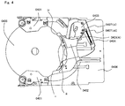
- the disc (0108) When inserting the 12cm diameter disc, as shown in Fig. 1(a) , at the outset, the disc (0108) contacts with the contacting pad in the basic position (0102) only at the contacting point (i). After that, the disc (0108) continues to move rightward in the diagram due to the rotational movement of the first driving unit for retraction (0101). Due to the movement, the contacting pad (0102) rotationally moves around the rotational axis for contacting pad (0110) in a direction of dashed arrow (I) (anticlockwise in the diagram). As a result, as shown in Fig. 4 , the disc (0408) contacts with three contacting points (i), (iii), and (iv) of the contacting pad (0402).
- a position of the contacting pad (0402) at this time is the 'sliding position when inserting 12cm diameter disc'. Therefore, the contacting pad (0402) slides rightward in the diagram maintaining the sliding position in response to the subsequent movement of the disc upon retraction (rightward in the diagram).
- the three contacting points (i), (iii), and (iv) of the contacting pad contact with the 12cm diameter disc so as to vertically sandwich the disc (0108).
- the vertical position of the disc (0108) is precisely determined at a predetermined position.
- the above rotational movement of the contacting pad (0102) is implemented as follows.
- the contacting pad may have a plurality of sliding protrusions as shown by (v) to (viii) in Figs. 3(b) and (c).
- Fig. 3(b) shows a bottom view of the contacting pad.
- the guiding member (0106) may have a plurality of sliding grooves to slide the contacting pad in response to the retraction of the disc.
- Fig. 5(b) shows a bottom view of the guiding member of Fig. 5(a) .
- the plurality of sliding protrusions (v) to (viii) of the contacting pad are respectively inserted into the plurality of sliding grooves of the same reference codes (v) to (viii) of the 'guiding member' of Fig. 5(a) in a direction indicated in Fig. 3(a) .
- the plurality of sliding protrusions (v) to (viii) of the contacting pad are inserted into the plurality of sliding grooves of the same reference codes (v) to (viii) respectively.
- the sliding protrusions (vi) and (vii) are protrusions, which have major axes shorter than the widths of the sliding grooves, to which the protrusions are inserted.
- the sliding protrusions (v) and (viii) are protrusions, which have head portions with major axes longer than the widths of the sliding grooves on the top of the bodies with major axes equal to or shorter than the widths of the sliding grooves. Due to two head portions, as shown in Fig. 1(a) , the contacting pad (0102), whose sliding protrusions are inserted into the plurality of sliding grooves of the guiding member (0106), is not detached. Therefore, in Fig. 1(a) , the plurality of sliding protrusions of the contacting pad can move only within the range determined by the respective sliding grooves.
- the sliding protrusion (v) has a major axis shorter than the width of the sliding groove, to which the protrusion is inserted, and the sliding protrusion (viii) has a major axis nearly equal to the width of the sliding groove, to which the protrusion is inserted.
- the center of this sliding protrusion (viii) is the rotational axis (0110) for the contacting pad (0102).
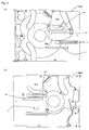
- Fig. 6 shows movement of the sliding protrusion when the contacting pad (0102, 0402) rotationally moves from the position of Fig. 1(a) to the position of Fig. 4 .
- the respective sliding protrusions of the contacting pad, located in the sliding grooves (v) to (viii) are indicated by small circles.
- White circles indicate sliding protrusions in a state of Fig. 1(a)
- black circles indicate sliding protrusions in a state of Fig. 4 .
- the sliding protrusion located in the sliding groove (viii) is not indicated by the black circle, and this means that this protrusion does not rotationally move.
- the sliding protrusions located in the sliding grooves (v) to (vii) rotationally move at the same rotational angle around the rotational axis (0110) of the sliding protrusion in the sliding groove (viii). Therefore, the width and the major axis of the respective grooves are designed to enable the rotational movement as shown in the diagram.
- the rotational movement of the contacting pad is implemented.
- the contacting pad rotationally moves as shown in Fig. 4 , the contacting points (i), (iii), and (iv) contact with the disc (0408).
- the contacting point (iii) or (iv) may have appropriate clearance between the disc, and the two points (i) and (iii), or (i) and (iv) may contact with the disc.
- the sliding protrusions (v) and (viii) can be inserted from wide portions located at the right edge of the sliding grooves (v) and (viii) (refer to Fig. 5(a) ). Therefore, widths of the wide portions located at the right edge of the sliding grooves (v) and (viii) are designed to be longer than those of the major axes of the head portions of the sliding protrusions (v) and (viii).
- the disc (0208) When inserting the 8cm diameter disc, as shown in Fig. 2 , at the outset, the disc (0208) contacts with the contacting pad in the basic position (0202) at the contacting points (ii) and (iii). Note that, in Fig. 2 , the contacting point (i) appears to contact with the disc (0208). However, the contacting point of the contacting pad (0202) is actually the shaded portion of Fig. 3(c) , and in Fig. 2 , the contacting point (i) have appropriate clearance between the disc, and does not come into contact with the disc.
- the disc (0208) After contacting the contacting pad (0202) at two contacting points (ii) and (iii), the disc (0208) continues to move rightward in the diagram due to the rotational movement of the first driving unit for retraction (0201). At this time, the contacting pad (0202) moves rightward in the diagram contacting with the disc at the two contacting points (ii) and (iii) without changing the basic position.
- a position (basic position) of the contacting pad (0202) at this time is the 'sliding position when inserting 8cm diameter disc'. Note that, the two contacting points (ii) and (iii) of the contacting pad contact with the 8cm diameter disc so as to vertically sandwich the disc (0208). As a result, the vertical position of the disc (0208) is precisely determined at a predetermined position.
- the contacting pad (0202, 0402) takes the sliding position (i.e. the 'sliding position when inserting 12cm diameter disc' in Fig. 2 , or the 'sliding position when inserting 8cm diameter disc' in Fig. 4 ) in response to diameter of the inserted disc.
- the contacting pad maintaining the sliding position, slides in a direction of retracting the disc inward of the device (rightward in the diagram) in response to subsequent retraction of the disc.
- a guiding member (0106, 0206), including a plurality of sliding grooves to slide the contacting pad in response to the retraction of the disc may be provided, and the contacting pad (0202, 0402) may include a plurality of sliding protrusions inserted into the sliding grooves.
- the sliding groove (vi) of the guiding member (0606) may have a groove portion (0611), which is designed to be wide for enabling the rotational movement, and a groove portion (0612), which is designed to be biforked and to have width nearly equal to a major axis of the sliding protrusion.
- the sliding protrusion located in the sliding groove slides in one of the biforked grooves in response to the sliding position of the contacting pad.
- the sliding protrusion rotationally moves from the white circle to the black circle, and slides in the upper sliding groove in the diagram.
- the protrusion moves from the white circle to the lower sliding groove, and slides therein.
- the biforked sliding groove is designed to have a width nearly equal to a major axis of the sliding protrusion. Therefore, when the sliding protrusion is located in the groove, in the diagram, vertical movement of the sliding protrusion is restricted, and only horizontal movement is possible.
- the timings of starting movements between the plurality of sliding protrusions may be determined in response to the contacting points of the contacting pad with the disc.
- the sliding position of the sliding contacting pad may be determined in response to the timings of starting movements between the plurality of sliding protrusions.
- the contacting pad (0102) contacts the disc (0108) only at the contacting point (i). Due to the force only on the contacting point (i) (rightward in the diagram), and due to press of the protrusion (vii) near the sliding protrusion (viii) leftward in the diagram by the after-mentioned biasing spring (0104), the sliding protrusions (v), (vi) and (vii) of the contacting pad (0102) start rotational movement (anticlockwise in the diagram) around the sliding protrusion (viii) ( Fig. 6 ).
- the disc (0108) moves rightward in the diagram the disc contacts the sliding protrusions (iii) and (iv), so that the contacting pad (0402) stops the rotational movement.
- the contacting pad (0402) takes the 'sliding position when inserting 12cm diameter disc'.
- the contacting points of the contacting pad (0402) with the disc (0408) are (i), (iii), and (iv).
- the retraction of the disc causes the force rightward in the diagram on the contacting points (i), (iii), and (iv), so that the sliding protrusions (v), (vi), (vii) and (viii) of the contacting pad (0402) ( Fig. 6 ) start sliding (rightward in the diagram). Therefore, the contacting pad (0402) slides in the 'sliding position when inserting 12cm diameter disc'.
- the contacting pad (0202) contacts the disc (0208) at the contacting points (ii) and (iii). Since the disc (0208) contacts at the contacting points (ii) and (iii) at the same time, due to the force on the contacting points (ii) and (iii) (rightward in the diagram), the sliding protrusions (v), (vi), (vii) and (viii) of the contacting pad (0202) start sliding rightward in the diagram at the same time. Therefore, the contacting pad (0202) slides in the 'sliding position when inserting 8cm diameter disc'.
- a 'connecting member' (0103) is configured to slide in response to variation of the sliding position (rotational movement), and a 'biasing spring' (0104) is configured to bias the sliding connecting member to return to an initial position.
- Fig. 7(a) shows the connecting member in a state of Fig. 1(a) or Fig2 (0103, 0203).
- Fig. 7(b) shows a bottom view of the connecting member of Fig. 7(a) . As shown in Figs.
- the connecting member (0703) includes the guiding protrusions (0705(A) and 0705(B)), latching protrusions (0707(xi) and 0707(xii)), and protrusions for ejecting shifter (0714) on both sides. Additionally, the sliding grooves (vii) and (x) are also included.
- FIG. 1(a) positional relation among the contacting pad (0102), the connecting member (0103) and guiding member (0106) is described.
- the diagram shows the guiding member (0106), the connecting member (0103), and the contacting pad (0102) in order from back to front.
- the protrusion (x) ( Fig. 6 ) of the guiding member (0106) is inserted into the sliding groove (x) ( Fig. 7(a) ) of the connecting member (0103).
- the guiding protrusion (0705(B)) of the connecting member is inserted into the sliding groove (ix) ( Fig. 6 ) of the guiding member.
- the sliding protrusion (vii) Fig.
- FIG. 8 shows movement of the guiding protrusion (0705(B)) when the connecting member (0103, 0403) slides from the position of Fig. 1 (a) to Fig. 4 .
- the guiding protrusion located in the sliding grooves (ix) (0805(B)) is indicated by small circles.
- White circle indicates the guiding protrusion in a state of Fig. 1(a)
- black circle indicates the guiding protrusion in a state of Fig. 4 .
- the guiding protrusion (0705(B)) slides in the sliding groove (ix) upon the slide of the connecting member (0103).
- the connecting member (0103) and the guiding protrusions (01 05(A), (B)) of the connecting member slide upon the rotational movement of the contacting pad (0102), and the contacting pad (0102) rotationally moves only when inserting the 12cm diameter disc. Therefore, the connecting member (0103) and the guiding protrusions (0105(A), (B)) of the connecting member slide only when inserting the 12cm diameter disc.
- the connecting member (0103) is biased clockwise, so that the contacting pad (0102) is also biased leftward in Fig. 1(a) through the sliding groove (vii) and the sliding protrusion (vii) of the contacting pad (0102).
- the biasing spring (0104) appropriately biases the connecting member (0103) in the state of Fig. 1(a) .
- the biasing force of the biasing spring is smaller than the retracting force of the first driving unit for retraction (0401). Therefore, as shown in Fig. 4 , when the disc (0408) moves rightward by the force of the first driving unit for retraction (0401) (when retracting the disc), the connecting member (0403) maintains the state of Fig.
- the connecting member (0403) returns from the position after sliding (0403) to the original position (0103) due to the biasing force of the biasing spring (0404).
- the contacting pad (0102, 0402) upon the slide of the connecting member (0103, 0403) due to the biasing force of the biasing spring, the contacting pad (0102, 0402) also rotationally moves (clockwise in the diagram), and returns from the 'sliding position when inserting 12cm diameter disc' to the basic position.
- the 'connecting member' (0203, 0403) is configured to rotationally move in response to the sliding of the contacting pad (0202, 0402). Moreover, the 'guiding protrusion' (0705(B) in Fig. 7 ) of the connecting member (0203) rotationally moves in different trajectory in response to the sliding position of the contacting pad (0202, 0402). Moreover, the 'connecting member' (0206, 0406) may have a sliding groove to make the guiding protrusion (0705(B)) rotationally move in different trajectory.
- description is provided with reference to diagrams. When the contacting pad (0202, 0402) slides rightward in the diagram in the sliding position of Fig.
- the connecting member (0203, 0403) is biased rightward due to the sliding protrusion (vii) ( Fig. 3(b) ) of the contacting pad (0202, 0402) inserted into the sliding groove (vii) ( Fig. 7(a) ).
- the connecting member rotationally moves anticlockwise in the diagram around the protrusion (x) ( Fig. 6 ) of the guiding member (0206, 0406) as a rotational axis, inserted into the sliding groove (x) ( Fig. 7(a) ).
- the connecting member slides in response to the variation of the sliding position (rotational movement) of the contacting pad.
- the contacting pad When inserting the disc into the device, the contacting pad is guided by the sliding grooves (v) to (viii) ( Fig. 6 ) of the guiding member (0606), thereby sliding (rightward in the diagram). Moreover, the connecting member is guided by the sliding groove (ix) ( Fig. 6 ), thereby rotationally moving (anticlockwise in the diagram) simultaneously with the slide of the contacting pad.
- the slide of the contacting pad and the rotational movement of the connecting member are configured such that if any one of them stops, the others also stop.
- the 'shifter' has a function of sliding in a direction of retracting the disc, and slides toward the retraction position of the disc. Therefore, the disc is inserted to the predetermined position in the device, and the shifter transfers a driving unit to a predetermined position in the device, thereby reading the disc data.
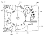
- Fig. 12 shows a bottom view of the 'shifter' (1415) in a state of Fig. 14 .
- the shifter includes a portion for ejection of the 8cm diameter disc (1216) and a portion for ejection of the 12cm diameter disc (1217).
- the portion for ejection (1216, 1217) contacts with a protrusion for ejecting shifter (0214, 0414) of the connecting member (0203, 0403) rotationally moving in a different trajectory in response to the sliding position of the contacting pad (0202, 0402), in the rotational trajectory.
- the shifter may include two guiding grooves for latching protrusion (1220(xi), 1220(xii)) in the lower-left portion in the diagram.
- One of the latching protrusions (0707(xi), 0707(xii) in Fig. 7 ) of the connecting member rotationally moving in a different trajectory in response to the sliding position of the contacting pad is inserted into one of the guiding grooves for latching protrusion (1220(xi), 1220(xii)).
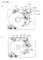
- Fig. 11 is a diagram showing operations in the disc drive device when inserting the 8cm diameter disc.
- FIG. 11 (b), (c), and (d) are perspective diagrams of the disc drive device, and the operations executed in the order of (b), (c), and (d).
- the connecting member (1103) in the state in Fig. 11 (b) rotationally moves in response to the slide of the contacting pad (1102), and comes to be in the state of Fig. 11 (c)
- the protrusion for ejecting shifter (1114) of the connecting member (1103) contacts with the portion for ejection of shifter (1116) of the shifter (1115), so that the shifter (1115) starts sliding leftward in the diagram as described above.
- the latching protrusion (0707(xi)) of the connecting member (1103) is inserted into the guiding grooves for latching protrusion (1220(xi)) of the shifter (1115)
- the rotational movement anticlockwise in the diagram of the latching protrusion (0707(xi)) is restricted, thereby stopping the rotational movement anticlockwise in the diagram of the connecting member (1103). Therefore, at this time, the rotational movement of the connecting member (1103) in response to the slide of the contacting pad (1102) stops.
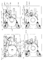
- FIG. 13(A) and 13(B) are diagrams showing operations in the disc drive device when inserting the 12cm diameter disc.
- FIG. 13(b), (c) , (d) and (e) are perspective diagrams of the disc drive device, and the operations executed in the order of (b), (c), (d) and (e).
- FIG. 13(b), (c) , (d) and (e) are perspective diagrams of the disc drive device, and the operations executed in the order of (b), (c), (d) and (e).
- the protrusion for ejecting shifter (1314) of the connecting member (1303) contacts the portion for ejection of shifter (1317) of the shifter (1315), so that the shifter (1315) starts sliding leftward in the diagram as described above.
- the latching protrusion (1307(xi)) of the connecting member (1303) is inserted into the guiding grooves for latching protrusion (1320(xi)) of the shifter (1315).
- the rotational movement anticlockwise in the diagram of the latching protrusion (1307(xi)) is restricted, thereby stopping the rotational movement anticlockwise in the diagram of the connecting member (1303). Therefore, at this time, the rotational movement of the connecting member (1303) in response to the slide of the contacting pad (1302) stops.
- the slide of the contacting pad and the rotational movement of the connecting member are configured such that if any one of them stops, the others also stop. Therefore, due to the rotational movement of the connecting member in response to the respective disc diameter, the slide of the contacting pad in response to the retraction of the disc stops. At this time, each disc of different diameter is placed such that the disc is located at a predetermined relative position to the center of a turntable ( Figs. 9 and 10 ).
- the shifter may include grooves (1220(xiii), 1220(xiv)) at the edge portion of the guiding grooves for latching protrusion (1220(xi), 1220(xii)) for varying trajectory of the latching protrusion moving in the guiding grooves for latching protrusion.
- the latching protrusion (1107(xi)) of the connecting member (1103) When the latching protrusion (1107(xi)) of the connecting member (1103) reaches to the periphery of the edge of the guiding grooves for latching protrusion (1120(xi)) of the shifter (1115), the latching protrusion (1107(xi)) is lifted upper-rightward in the diagram due to a varying portion for trajectory (1120(xiii)) of the guiding grooves for latching protrusion. As a result, the connecting member (1103) rotationally moves anticlockwise in the diagram. Due to the rotational movement of the connecting member, the contacting pad (1102) slides rightward in the diagram and separates from the disc. The case of inserting the 8cm diameter disc is described above, and the case of inserting the 12cm diameter disc is similarly processed, and the contacting pad separates from the disc located at the predetermined relative position to the center of the turntable.
- FIG. 11 processing of the case of inserting the 8cm diameter disc is described.
- the disc (1108) is transferred in an inward direction of the device (rightward in the diagram) due to the rotation of the roller of the first driving unit for retraction (1101).
- the disc (1108) contacts with the contacting pad (1102) at the contacting points (ii) and (iii).
- the disc (1108) continues to move rightward in the diagram by the rotational movement of the first driving unit for retraction (1101), so that the contacting pad (1102) slides rightward in the diagram along the sliding groove of the guiding member (1106) as shown in Fig. 11(c) .
- the connecting member (1103) guided by the sliding groove (ix) of the guiding member (1106), rotationally moves anticlockwise in the diagram.
- the guiding protrusion (1105) of the connecting member (1103) moves in the short sliding groove (ix), which is located in the lower part of the diagram.
- the protrusion for ejecting shifter (1114) (0714 in Fig.
- the latching protrusion (1107(xi)) of the connecting member (1103) is inserted into the guiding grooves for latching protrusion (1120(xi)) of the shifter (1115).
- the rotational movement of the latching protrusion (1120(xi)) is restricted, thereby stopping the rotational movement anticlockwise in the diagram of the connecting member (1103).
- the contacting pad (1102) stops sliding rightward in the diagram, thereby stopping the movement of the disc.
- the disc (1108) is located at the predetermined relative position to the center of the turntable.
- the disc (1308) contacts the contacting pad (1302) at the contacting points (i), (iii) and (iv). Moreover, due to the rotational movement of the contacting pad (1302), the connecting member (1303) slides upper-rightward in the diagram. At this time, the guiding protrusion (1305) of the connecting member (1303) sides upper-rightward in the diagram in the sliding groove (ix) of the guiding member (1306) ( Fig. 13(b) to (C) ).
- the disc (1308) continues to move rightward in the diagram by the rotational movement of the first driving unit for retraction (1301), so that the contacting pad (1302) slides rightward in the diagram maintaining the sliding position due to the above rotational movement along the sliding groove of the guiding member (1106) as shown in Fig. 13(d) .
- the connecting member (1303) guided by the sliding groove (ix) of the guiding member (1306), rotationally moves anticlockwise in the diagram.
- the guiding protrusion (1305) of the connecting member (1303) moves in the long sliding groove (ix), which is located upper in the diagram.
- the protrusion for ejecting shifter (1314) (0714 in Fig. 7 ) of the rotationally moving connecting member (1303) contacts with the portion for ejection (1317) (1217 in Fig. 12 ) of the shifter (1315). Due to the rotational movement anticlockwise in the diagram of the connecting member (1303), the shifter (1315) is pushed leftward in the diagram. Due to movement leftward in the diagram of the shifter (1315), the jagged portion (1219 in Fig. 12 ) of the shifter (1315) is engaged with the gear (1318). Subsequently, the shifter (1315) is driven by the rotation of the gear (1318), thereby sliding to the predetermined position.
- the latching protrusion (1307(xii)) of the connecting member (1303) is inserted into the guiding grooves for latching protrusion (1320(xi)) of the shifter (1115).
- the rotational movement of the latching protrusion (1120(xi)) is restricted, thereby stopping the rotational movement anticlockwise in the diagram of the connecting member (1303).
- the contacting pad (1302) stops sliding rightward in the diagram, thereby stopping the movement of the disc.
- the disc (1308) is located at the predetermined relative position to the center of the turntable.
- the driving unit (not indicated), transferred by the shifter moved to the predetermined position, starts processing such as reading the data of the disc placed at the predetermined position.
- the driving unit (not indicated), transferred by the shifter moved to the predetermined position, starts processing such as reading the data of the disc placed at the predetermined position.
- the connecting member (1303) is guided by the sliding groove, thereby sliding lower-leftward in the diagram. Due to this, the connecting pad (1302) rotates clockwise in the diagram, thereby returning to the basic position.
- the disc drive device of the embodiment it is possible to precisely place the inserted disc on the predetermined position, where the disc can be driven, in response to its size using the slot-in system without expensive components such as a sensor and with smaller number of components comparing with the conventional technology. As a result, it is possible to save space in the device, thereby minimizing the size of the device. Moreover, it is possible to reduce the number of components, thereby reducing production cost.
Landscapes
- Feeding And Guiding Record Carriers (AREA)
- Holding Or Fastening Of Disk On Rotational Shaft (AREA)
Applications Claiming Priority (2)
| Application Number | Priority Date | Filing Date | Title |
|---|---|---|---|
| JP2008016477A JP2009176385A (ja) | 2008-01-28 | 2008-01-28 | ディスクドライブ装置 |
| PCT/JP2008/059748 WO2009096051A1 (ja) | 2008-01-28 | 2008-05-27 | ディスクドライブ装置 |
Publications (2)
| Publication Number | Publication Date |
|---|---|
| EP2249340A1 true EP2249340A1 (de) | 2010-11-10 |
| EP2249340A4 EP2249340A4 (de) | 2012-11-28 |
Family
ID=40912416
Family Applications (1)
| Application Number | Title | Priority Date | Filing Date |
|---|---|---|---|
| EP08776913A Withdrawn EP2249340A4 (de) | 2008-01-28 | 2008-05-27 | Plattenlaufwerkanordnung |
Country Status (8)
| Country | Link |
|---|---|
| US (1) | US8171505B2 (de) |
| EP (1) | EP2249340A4 (de) |
| JP (1) | JP2009176385A (de) |
| CN (1) | CN101925957B (de) |
| BR (1) | BRPI0821959A2 (de) |
| MX (1) | MX2010008020A (de) |
| RU (1) | RU2457554C2 (de) |
| WO (1) | WO2009096051A1 (de) |
Families Citing this family (5)
| Publication number | Priority date | Publication date | Assignee | Title |
|---|---|---|---|---|
| JP4308200B2 (ja) * | 2005-12-27 | 2009-08-05 | パイオニア株式会社 | ディスク装置 |
| JP4322869B2 (ja) * | 2005-12-28 | 2009-09-02 | パナソニック株式会社 | スロットイン型ディスク装置 |
| JP4322868B2 (ja) * | 2005-12-28 | 2009-09-02 | パナソニック株式会社 | スロットイン型ディスク装置 |
| JP2013041650A (ja) * | 2011-08-18 | 2013-02-28 | Funai Electric Co Ltd | 光ディスク装置 |
| JPWO2016151652A1 (ja) | 2015-03-24 | 2018-01-18 | パナソニックIpマネジメント株式会社 | ディスク搬送装置 |
Family Cites Families (17)
| Publication number | Priority date | Publication date | Assignee | Title |
|---|---|---|---|---|
| SU733012A1 (ru) * | 1978-07-11 | 1980-05-05 | Предприятие П/Я А-3103 | Устройство дл записи информации на магнитные диски |
| US5195079A (en) * | 1990-08-20 | 1993-03-16 | Teac Corporation | Disk driver in which the disk holder is located below a slider |
| JP2854161B2 (ja) * | 1991-06-12 | 1999-02-03 | 三洋電機株式会社 | ディスク位置設定機構 |
| JP2686904B2 (ja) * | 1993-12-10 | 1997-12-08 | アルパイン株式会社 | ディスクプレーヤ |
| US5957929A (en) * | 1997-05-02 | 1999-09-28 | Micro Therapeutics, Inc. | Expandable stent apparatus and method |
| KR100277960B1 (ko) | 1997-12-04 | 2001-01-15 | 윤종용 | 광 디스크 로딩장치 |
| JPH11265542A (ja) * | 1998-03-16 | 1999-09-28 | Alps Electric Co Ltd | ディスク排出装置 |
| JP3619133B2 (ja) * | 2000-08-31 | 2005-02-09 | 松下電器産業株式会社 | ディスクローディング装置 |
| JP4211964B2 (ja) * | 2000-11-10 | 2009-01-21 | クラリオン株式会社 | ディスク位置決め機構 |
| JP3690300B2 (ja) * | 2001-04-05 | 2005-08-31 | ソニー株式会社 | ディスク記録及び/又は再生装置 |
| KR100904244B1 (ko) | 2001-04-05 | 2009-06-25 | 소니 가부시끼 가이샤 | 디스크 기록 재생 장치 |
| EP1328107A1 (de) * | 2002-01-11 | 2003-07-16 | Siemens Aktiengesellschaft | Verfahren zum Ermitteln eines Diensterbringungsprogramms, zugehörige Einheiten und zugehöriges Programm |
| JP4106422B2 (ja) * | 2002-07-08 | 2008-06-25 | 株式会社ケンウッド | ディスクガイド機構及びこのディスクガイド機構を用いたディスク再生装置 |
| JP2006185565A (ja) * | 2004-12-28 | 2006-07-13 | Orion Denki Kk | ディスク装置を備えた電子機器 |
| JP2006302384A (ja) | 2005-04-19 | 2006-11-02 | Funai Electric Co Ltd | 光ディスク再生装置 |
| US7840972B2 (en) * | 2006-02-16 | 2010-11-23 | Toshiba Samsung Storage Technology Korea Corporation | Optical disc device and method of controlling the same |
| JP4687566B2 (ja) * | 2006-05-24 | 2011-05-25 | ティアック株式会社 | ディスク装置 |
-
2008
- 2008-01-28 JP JP2008016477A patent/JP2009176385A/ja active Pending
- 2008-05-27 BR BRPI0821959A patent/BRPI0821959A2/pt not_active IP Right Cessation
- 2008-05-27 MX MX2010008020A patent/MX2010008020A/es active IP Right Grant
- 2008-05-27 CN CN2008801255994A patent/CN101925957B/zh not_active Expired - Fee Related
- 2008-05-27 WO PCT/JP2008/059748 patent/WO2009096051A1/ja not_active Ceased
- 2008-05-27 US US12/864,842 patent/US8171505B2/en not_active Expired - Fee Related
- 2008-05-27 RU RU2010136019/28A patent/RU2457554C2/ru not_active IP Right Cessation
- 2008-05-27 EP EP08776913A patent/EP2249340A4/de not_active Withdrawn
Also Published As
| Publication number | Publication date |
|---|---|
| US8171505B2 (en) | 2012-05-01 |
| CN101925957A (zh) | 2010-12-22 |
| JP2009176385A (ja) | 2009-08-06 |
| RU2010136019A (ru) | 2012-03-10 |
| MX2010008020A (es) | 2010-08-11 |
| US20100313211A1 (en) | 2010-12-09 |
| RU2457554C2 (ru) | 2012-07-27 |
| WO2009096051A1 (ja) | 2009-08-06 |
| CN101925957B (zh) | 2013-01-16 |
| EP2249340A4 (de) | 2012-11-28 |
| BRPI0821959A2 (pt) | 2019-09-24 |
| HK1150301A1 (en) | 2011-11-18 |
Similar Documents
| Publication | Publication Date | Title |
|---|---|---|
| US6839898B2 (en) | Disk drive | |
| US6826766B2 (en) | Disk apparatus | |
| US8171505B2 (en) | Disc drive device | |
| JPH11250543A (ja) | 記録媒体記録再生装置 | |
| US20080052731A1 (en) | Slot-in disk drive device | |
| JPWO2005101401A1 (ja) | ディスク装置 | |
| US7934225B2 (en) | Slot-in disk drive device and method | |
| JP4376756B2 (ja) | ディスク装置 | |
| JP4281704B2 (ja) | ディスク駆動装置及び電子機器 | |
| US8220008B2 (en) | Disk apparatus with resilient member on cam mechanism connecting a main slider to a sub-slider | |
| JP2005327431A5 (de) | ||
| US8060896B2 (en) | Method and device for protecting slot-in optical disc drive | |
| US20110247020A1 (en) | Disk unit for conveying disks of different diameters | |
| US8015575B2 (en) | Disk device with insertion slot capable of preventing double loading of disks | |
| US8255935B2 (en) | Slot-in type disk apparatus in which a disk is directly operated by a lever | |
| EP1087391B1 (de) | Platteneinheit | |
| US20060245313A1 (en) | Disc drive and drive control method of disc drive | |
| US8060898B2 (en) | Head driving device and disk apparatus | |
| US20090133043A1 (en) | Transfer Device and Recording Medium Driving Device | |
| KR102301958B1 (ko) | 광 디스크 드라이브 | |
| JP4525482B2 (ja) | ディスク駆動装置及び電子機器 | |
| CN1954378A (zh) | 光盘装置 | |
| HK1150301B (en) | Disc drive device | |
| JP2009020956A (ja) | ディスク搬送機構およびこのディスク搬送機構を用いたディスク再生装置 | |
| JP2008159093A (ja) | 記録媒体駆動装置及び電子機器 |
Legal Events
| Date | Code | Title | Description |
|---|---|---|---|
| PUAI | Public reference made under article 153(3) epc to a published international application that has entered the european phase |
Free format text: ORIGINAL CODE: 0009012 |
|
| 17P | Request for examination filed |
Effective date: 20100826 |
|
| AK | Designated contracting states |
Kind code of ref document: A1 Designated state(s): AT BE BG CH CY CZ DE DK EE ES FI FR GB GR HR HU IE IS IT LI LT LU LV MC MT NL NO PL PT RO SE SI SK TR |
|
| AX | Request for extension of the european patent |
Extension state: AL BA MK RS |
|
| DAX | Request for extension of the european patent (deleted) | ||
| A4 | Supplementary search report drawn up and despatched |
Effective date: 20121025 |
|
| RIC1 | Information provided on ipc code assigned before grant |
Ipc: G11B 17/051 20060101AFI20121019BHEP |
|
| STAA | Information on the status of an ep patent application or granted ep patent |
Free format text: STATUS: THE APPLICATION IS DEEMED TO BE WITHDRAWN |
|
| 18D | Application deemed to be withdrawn |
Effective date: 20130524 |