EP2249366B1 - Dispositif de signalisation pour disjoncteur et appareil électrique comprenant le dispositif de signalisation - Google Patents
Dispositif de signalisation pour disjoncteur et appareil électrique comprenant le dispositif de signalisation Download PDFInfo
- Publication number
- EP2249366B1 EP2249366B1 EP09159564.5A EP09159564A EP2249366B1 EP 2249366 B1 EP2249366 B1 EP 2249366B1 EP 09159564 A EP09159564 A EP 09159564A EP 2249366 B1 EP2249366 B1 EP 2249366B1
- Authority
- EP
- European Patent Office
- Prior art keywords
- pivoting
- pivoting body
- signalling device
- circuit breaker
- return spring
- Prior art date
- Legal status (The legal status is an assumption and is not a legal conclusion. Google has not performed a legal analysis and makes no representation as to the accuracy of the status listed.)
- Active
Links
Images


Classifications
-
- H—ELECTRICITY
- H01—ELECTRIC ELEMENTS
- H01H—ELECTRIC SWITCHES; RELAYS; SELECTORS; EMERGENCY PROTECTIVE DEVICES
- H01H71/00—Details of the protective switches or relays covered by groups H01H73/00 - H01H83/00
- H01H71/10—Operating or release mechanisms
- H01H71/12—Automatic release mechanisms with or without manual release
- H01H71/46—Automatic release mechanisms with or without manual release having means for operating auxiliary contacts additional to the main contacts
- H01H71/465—Self-contained, easily replaceable microswitches
Definitions
- the present invention relates to the field of the signalling devices to be connected to circuit beakers, or other electrical switches, in order to provide an electrical signal indicating a state transition performed by the circuit breaker.
- a traditional signalling device comprises a body which moves under the action of a kinematic mechanism of the circuit breaker. During this movement, the body interacts with and thereby actuates an actuating mechanism of a micro-switch.
- the micro-switch is configured to provide an electrical signal indicating the transition performed by the circuit breaker.
- This known signalling device is conceived in order to have a long lifecycle and perform several thousands operation.
- International patent application WO 01/16984 discloses a circuit interrupter with an accessory case socket into which an accessory bell alarm member is disposed. A two-piece lever arrangement is provided in the bell alarm accessory case between the micro-switch button and the operating mechanism of the circuit breaker.
- the operating mechanism rotates the entire two-piece member as a single unit until the bell alarm button has been completely depressed, after which over-travel of the operating mechanism is accommodated by rotational movement of only one of the members on a common axis against the force of a hub located torsion spring.
- a signalling device suitable to be operatively coupled to a circuit breaker, which comprises:
- the return spring and the pivoting body are mounted coaxially around the same axis.
- the return spring is a torsion coil spring.
- the signalling device 100 can provide an electrical signal indicating that the circuit breaker to which is associated is switched from a first state to a second state and, particularly, from the closed position wherein the movable and fixed contacts of the circuit breaker are electrically coupled to each other, to the open state wherein the movable contacts of the circuit breaker are separated from the corresponding fixed contacts.
- This type of signalling devices indicating a transition performed by the circuit breaker can be also referred to as a "transient contact".
- the signalling device 100 comprises an electrical switch 1, an actuating mechanism 2 for actuating the electrical switch 1, a movable body 3 (hereinafter “pivoting body") which is pivotally mounted around a first axis 101 so as to interact with the actuating mechanism 2; and a return spring 14 which is operatively connected to the pivoting body 3 and is mounted around a second axis substantially parallel to the first axis 101.
- the first axis 101 and the second axis substantially coincide, i.e. the return spring 14 is mounted coaxially with the pivoting body 3 around the first axis 101.
- the return spring 14 is a torsion spring, more preferably a torsion coil spring as shown in the figures.
- the signaling device 100 preferably comprises a transmission mechanism 4 suitable to be operatively coupled to the circuit breaker.
- the above mentioned elements are mounted on and supported by a base 11 made for example of metallic material, such as steel.
- the electrical switch 1 is for example a known micro-switch, particularly a low voltage switch, provided with a movable contact and a fixed contact (not shown); such a switch 1 is well known to the skilled man and therefore will not be described in detail hereinafter.
- the actuating mechanism 2 shown in the figures comprises a shaped lever 5, e.g. an S-shaped lever which is operatively connected to the movable contact of the micro-switch 1.
- the lever 5 has a first end arm 6 pivotally connected to a connection element 40 rigidly fixed to an enclosure of the electrical switch 1; moreover, a tension spring 12 acts on the first end arm 6.
- a second end arm 7 of the S-shaped lever 5 is connected to a piston such as, for example, a pneumatic piston 8 which is suitable to dampen the pushing action of the lever 5.
- the actuating mechanism 2 further includes a roller or rotating sleeve 9, which is mounted on the second end arm 7 so as to be contacted by a lateral edge 10 of the pivoting body 3.
- the lateral edge 10 can push the rotating sleeve 9 so as to cause a movement of the lever 5 which is transferred to the piston 8 and the spring 12 and thus causes the actuation of the switch 1.
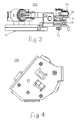
- the pivoting body 3 which is preferably cam shaped, is pivotally mounted so at to rotate about the first axis 101; in particular, the pivoting body 3 is articulated around a first pivot 13 which is transversely, e.g. perpendicularly, connected to the base 11.
- the pivoting body 3 is pivotally connected to the pivot 13 by means of a block element such as, for example, a first clip 17.
- the first pivot 13 is rotatable housed inside a hollow element 27 ( FIG. 5 ), such as a sleeve, rigidly connected to the base 11.
- the pivoting body 3 can move between two different operative configurations.
- a first configuration the pivoting body 3 stays in a rest position (as shown in FIG. 1 and in FIG. 2 ) in which it does not interact with the actuating mechanism 2 of the micro-switch 1.
- the pivoting body 3 performs a movement. Indeed, the pivoting body 3 firstly rotates (e.g. in an anticlockwise direction indicated by the arrow F1 in FIG. 2 ) so as to push the rotating sleeve 9 of the actuating mechanism 2 and arrive up to a second position (hereinafter "final position") shown in FIG. 5 . Secondly, the pivoting body 3 rotates in an opposite direction (i.e. clockwise direction corresponding to the arrow F2) so as to move from the final position ( FIG. 5 ) and assume again the rest position ( FIG.1 ).
- the rotation of the pivoting body 3 from the rest position to the final position is caused by the action of the kinematic mechanism of the circuit breaker.
- the kinematic mechanism can act on the transmission mechanism 4 which in turns transmits the movement to the pivoting body 3; or in alternative, the kinematic mechanism of the circuit breaker could act directly on the pivoting body 3.
- the circuit breaker causes the rotation of the pivoting body 3 towards the final position when the circuit breaker switches from the closed state to the open state.
- the opposite transition i.e. from the open state to the closed state does not substantially produce any rotation of the pivoting body 3.
- the first return spring 14 is arranged and operatively coupled to the pivoting body 3 in such a way that when the pivoting body 3 rotates from the rest position towards the final position the first return spring 14 is subject to a mechanical moment (i.e. a moment of force), preferably a torque, which causes a preloading of the first return spring 14.
- a mechanical moment i.e. a moment of force
- a torque preferably a torque
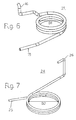
- the first torsion coil spring 14 (also shown in FIG. 6 ) is preferably mounted coaxially with the pivoting body 3; in particular, the spring 14 is arranged around the first pivot 13 and is provided with a first end 15 operatively connected to the base 11 and a second end 16 operatively connected to the pivoting body 3.
- the first coil spring is subject to a mechanical moment that causes a rotation of the second end 16 producing a preloading compression of the first torsion coil spring 14.
- the first torsion coil spring 14 When the pivoting body 3 reaches the final position ( FIG, 5 ) the first torsion coil spring 14, by releasing the energy accumulated during its loading compression, act on and biases the pivoting body 3 thus causing the rotation of the pivoting body 3 from the final position to the rest position.
- the first torsion coil spring 14 may comprise 2.5 - 5 turns (e.g. 3.4 turns), has an internal diameter D1 of 15-25 mm (e.g. 20 mm) and a theoretical spring constant of about 2600-4000 Nmm/° (e.g. 3640 Nmm/°).
- the coil wire diameter ranges, for instance, between 1.5 and 3 mm (e.g. 2 mm).
- the first torsion coil spring 14 in made of any suitable metallic material, such as, for example AISI 302 or 304 stainless steel.
- the transmission mechanism 4 which allows transmitting the movement of the kinematic mechanism of the circuit breaker to the pivoting body 3.
- the transmission mechanism 4 includes a pivoting lever 18 and a second pivot 19 around which the pivoting lever 18 can rotate.
- the second pivot 19 is bolted to the pivoting body 3 and extends transversely, e.g. perpendicularly, to such body.
- the exemplary pivoting lever 18 shown in the figures is L-shaped and its vertex is provided with a hole for the passing through of the second pivot 19 to which is pivotally fixed by means of a second clip 20 ( FIG. 1 ).
- a first arm 21 of the pivoting lever 18 is arranged in such a way to allow a contact with a portion of the kinematic mechanism of the circuit breaker.
- a second arm 22 of the pivoting lever 18 abuts against a pushing element of the pivoting body 3.
- such pushing element is the above mentioned hollow body 27.
- the transmission mechanism 4 also includes a second return spring 24 ( FIG. 3 and FIG. 7 ) acting on the pivoting lever 18 to rotate the latter between an intermediate position assumed under the action of the portion of the circuit breaker and an operative position to be assumed when the pivoting body 3 is in the rest position.
- a second return spring 24 ( FIG. 3 and FIG. 7 ) acting on the pivoting lever 18 to rotate the latter between an intermediate position assumed under the action of the portion of the circuit breaker and an operative position to be assumed when the pivoting body 3 is in the rest position.
- this second return spring 24 acts when the pivoting body 3 is in the rest position and the circuit breaker switches from the above mentioned open state to the closed state. In this transition the kinematic mechanism of the circuit breaker engages the first arm 21 of the pivoting lever 18 producing a clockwise rotation of the latter which does not involve the pivoting body 3.
- the second return spring 24 is arranged so as to rotate the pivoting lever 18 in anticlockwise direction in order to bring such lever in the operative position shown in FIG. 1 .
- the second return spring 24 can be any type of spring suitable to bring again the pivoting lever 18 in the position in which it engages the hollow element 27 of the pivoting body 3.
- the second return spring 24 is similar to the first return spring 14 and therefore is arranged in such a way that when the pivoting lever 18 rotates from the operative position towards the intermediate position the second return spring 24 is subject to a moment of force which causes a preloading of such spring 24.
- said moment of force can be a flexure moment or a torque.
- the second return spring 24 can be a flexure spring (e.g. a cantilever spring or a leaf spring) or, more preferably, a torsion spring, as the one shown in the figures.
- the second torsion spring 24 shown in FIG. 7 is a torsion coil spring.
- the second torsion coil spring 24 is arranged around the second pivot 19 and is provided with a respective first end 25 operatively connected to the pivoting body 3 and a second end 26 operatively connected with the pivoting lever 18.
- the second coil spring 24 is submitted to a moment of force that causes a preloading compression of the second coil spring 24. Then the preloaded second coil spring 24 acts so as to bias the pivoting lever 18 and produce its return rotation (anticlockwise direction) to reach the operative position.
- the second torsion coil spring 24 includes about 2 - 3.5 turns (e.g. 2.8 turns), has an internal diameter D2 of 8-12 mm (e.g. 10.4 mm) and a theoretical spring constant of 1.8 - 2.2 Nmm/° (e.g. 0.2 Nmm/°).
- the coil wire diameter ranges, for instance, between 0.4 and 0.8 mm (e.g. 0.6 mm).
- the second return spring can be a tension spring (not shown) having an end connected to the second arm 22 of the pivoting lever 18 and another end connected to a pin element (not shown) fixed to the base 11.
- the signalling device 100 comprises a first stop abutment 28 placed so as to stop the stroke of the pivoting body 3 at the final position ( FIG. 5 ).
- the stop abutment 28 comprises a supporting wall 29 provided with a first shock absorber 30.
- the supporting wall 29 can be a plate rigidly fixed to the base 11.
- the supporting wall 29 is made in one piece with the base 11, as an example, using a molding manufacturing process.
- the shock absorber 30 can be, for instance, a rubber element fixed, e.g. by means of glue, to an internal surface of the supporting wall 29 so as to be hit by the lateral edge 10 of the pivoting body 3 when it rotates in the anticlockwise direction.
- the signalling device 100 is also provided with a second stop abutment 31 ( FIG. 1 and FIG. 5 ) placed to stop the pivoting body 3 at the rest position.
- the second stop abutment 31 can be analogous to the first stop abutment 28 and includes a further supporting wall 32 and a further shock absorber 33.
- the further shock absorber 33 is placed so as to be hit by another side wall 34 of the pivoting body 3, opposite to the side wall 10.
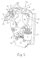
- FIG. 8 shows a portion of an electrical apparatus 200 comprising a circuit breaker provided with a kinematic mechanism 35 and the above described signalling device 100.
- the kinematic mechanism 35 is well known to a man skilled in the art and includes a shaft 36 connected to cranks 37 and to an activating cam element 38 provided with a tooth 39.
- the tooth 39 is arranged to engage the first arm 21 of the pivoting lever 18.
- FIG. 8 depicts the particular situation in which the circuit breaker is already switched from the closed state (i.e. corresponding to the closing of an associated electric circuit) to the open state (i.e. corresponding to the opening of the electric circuit) and the tooth 39 is on the left side with respect the pivoting lever 18, as visible in FIG. 8 .
- the circuit breaker switches (e.g. due to a fault) towards the open state and the cam element 38 rotates in a clockwise direction to cause the tooth 39 pushes the first arm 21 of the pivoting lever 18.
- the second arm 22 of the pivoting lever 18 acts on the hollow element 27 of the pivoting body 3 which rotates in an anticlockwise direction. It has to be observed that the cam element 38 of the circuit breaker gives a relevant kinetic energy to the pivoting body 3.
- the pivoting body 3 engages the element 9 producing a closing switching of the micro-switch 1 that provides an electrical signal, e.g. to a control unit, indicating that a transition of the circuit breaker towards the open state has occurred.
- the first torsion coil spring 14 is loaded thanks to this anticlockwise rotation of the pivoting body 3.
- the pivoting body 3 is then stopped in the final position by the first stop abutment 28 which is realized so as to absorb the high energy hit produced by the pivoting body 3 and to reduce any mechanical stress for both the pivoting body 3 and the whole structure of the signalling device 100.
- the first torsion coil spring 14 releases the loaded elastic energy and causes the pivoting body 3, together with the pivoting lever 18, to rotate clockwise and return back from the second position to the rest position (situation illustrated in FIG. 8 ).
- the second or final position is a movement reverse position for the pivoting body 3.
- the pivoting body 3 is then stopped in the rest position by the second stop abutment 31 that contributes to reduce any mechanical stress for both the pivoting body 3 and the whole structure of the signalling device 100.
- the tooth 39 acts on the first arm 21 of the pivoting lever 18.
- the pivoting lever 18 rotates in a clockwise direction leaving the operative position and reaching the intermediate position. This rotation caused by the tooth 39 loads the second torsion coil 24 which consequently releases the corresponding elastic energy by drawing back the pivoting lever 18 in the operative position.
- the signalling device 100 of the present invention offers some improvements over signalling devices of known type having the same functionalities.
- the purposive structure devised and the use of the first and second torsion coil springs 14 and 24, allow having a reduced mechanical stress and an overall increased lifecycle of the device itself.
- the signalling device thus conceived may undergo numerous modifications and come in several variants, all falling within the scope of the inventive concept as defined by the appended claims; for example, the various components of the actuating mechanism, or of the transmission mechanism may be differently shaped or may be constituted by a different number of parts, the pivoting body 3 can be differently shaped, et cetera.
- the component materials and dimensions of the device may be of any type, according to needs and the state of the art.
Landscapes
- Driving Mechanisms And Operating Circuits Of Arc-Extinguishing High-Tension Switches (AREA)
- Breakers (AREA)
Claims (13)
- Dispositif de signalisation (100) apte à être couplé de manière fonctionnelle à un disjoncteur, comprenant :un commutateur électrique (1) configuré de manière à générer un signal électrique indiquant une transition du disjoncteur d'un premier état à un second état ;un mécanisme d'actionnement (2) destiné à actionner le commutateur électrique ;un corps mobile (3) qui est monté de manière pivotante autour d'un premier axe (101) de façon à interagir avec le mécanisme d'actionnement ; etun ressort de rappel (14) qui est relié de manière fonctionnelle au corps pivotant (3) et est monté autour d'un axe sensiblement parallèle audit premier axe, et comportant en outre un mécanisme de transmission (4) apte à interagir de manière fonctionnelle avec le disjoncteur de façon à provoquer une rotation du corps pivotant correspondant à ladite transition du disjoncteur du premier état au second état, caractérisé en ce que le mécanisme de transmission (4) comprend :un levier pivotant (18) doté d'un premier bras (21) devant être poussé par une partie (39) du disjoncteur, et d'un second bras (22) destiné à venir en butée contre un élément poussoir d'activation (27) du corps pivotant (3) en vue d'occasionner une configuration de pivotement dans laquelle il entre en rotation ;un pivot supplémentaire (19) fixé sur ledit corps pivotant autour duquel le levier pivotant peut entrer en rotation ; etun ressort de rappel supplémentaire (24) agissant sur le levier pivotant en vue de faire entrer en rotation le levier pivotant entre une position intermédiaire prise sous l'action de la partie du disjoncteur et une position fonctionnelle devant être prise lorsque le corps pivotant se trouve dans une position de repos.
- Dispositif de signalisation (100) selon la revendication 1, dans lequel ledit ressort de rappel est monté de manière coaxiale avec ledit corps pivotant (3) autour dudit premier axe (101).
- Dispositif de signalisation (100) selon l'une quelconque des revendications précédentes, dans lequel ledit corps pivotant (3) est apte à prendre ladite position de repos et ladite configuration de pivotement dans laquelle il entre en rotation afin d'interagir avec le mécanisme d'actionnement, il atteint une position finale et il revient à la position de repos, et dans lequel le ressort de rappel (14) est relié fonctionnellement au corps pivotant (3) de sorte que, lorsque le corps pivotant (3) effectue une rotation vers la position finale, le ressort de rappel est soumis à un moment de force provoquant sa précontrainte, ledit ressort de rappel déplaçant ensuite le corps pivotant de la position finale à la position de repos.
- Dispositif de signalisation (100) selon l'une quelconque des revendications précédentes, dans lequel ledit ressort de rappel est un ressort hélicoïdal de torsion (14).
- Dispositif de signalisation (100) selon la revendication 4, comprenant en outre :une base (11) prenant en charge au moins le corps pivotant et le ressort de rappel ;un premier pivot (13) fixé sur ladite base transversalement par rapport à un plan de pivotement du corps pivotant ; le ressort hélicoïdal de torsion (14) étant agencé autour dudit premier pivot et le corps pivotant (3) étant relié de façon pivotante audit premier pivot.
- Dispositif de signalisation (100) selon la revendication 5, dans lequel ledit ressort hélicoïdal de torsion est doté d'une première extrémité (15) interagissant avec la base (11) et d'une seconde extrémité (16) interagissant avec le corps pivotant, de sorte que le mouvement de la position de repos à la position finale provoque une contrainte du ressort de torsion.
- Dispositif de signalisation (100) selon l'une quelconque des revendications précédentes, comprenant en outre une butée d'arrêt (28) placée de manière à arrêter le corps pivotant (3) au niveau de la position finale.
- Dispositif de signalisation (100) selon la revendication 7, dans lequel ladite butée d'arrêt (28) comprend une paroi de support (29) dotée d'un premier amortisseur de chocs (30) pour entrer en contact avec une première paroi latérale (10) du corps pivotant (3).
- Dispositif de signalisation (100) selon la revendication 1, dans lequel ledit ressort de rappel supplémentaire (24) est agencé de sorte que, lorsque le levier pivotant (18) effectue une rotation de la position fonctionnelle à la position intermédiaire, ledit ressort de rappel supplémentaire est soumis à un moment de force.
- Dispositif de signalisation (100) selon la revendication 9, dans lequel ledit ressort de rappel supplémentaire est un ressort hélicoïdal de torsion supplémentaire monté autour du pivot supplémentaire et présentant une extrémité correspondante (26) agissant sur ledit levier pivotant.
- Dispositif de signalisation (100) selon la revendication 10, dans lequel le dispositif comprend une seconde butée d'arrêt (31) placée de manière à arrêter le corps pivotant (3) au niveau de la position de repos, ladite seconde butée d'arrêt (31) comprenant une paroi de support supplémentaire (32) dotée d'un second amortisseur de chocs (33) placé de manière à entrer en contact avec une seconde paroi latérale (34) du corps pivotant (3).
- Dispositif de signalisation (100) selon la revendication 1, dans lequel ledit corps pivotant est en forme de came.
- Appareil électrique (200) comprenant :un disjoncteur doté d'un mécanisme cinématique (35) ;un dispositif de signalisation (100) couplé de manière fonctionnelle audit mécanisme cinématique (35), en vue de générer au moins un signal électrique indiquant que le disjoncteur a effectué une transition d'un premier état à un second état ; etdans lequel ledit dispositif de signalisation est selon la revendication 1.
Priority Applications (4)
| Application Number | Priority Date | Filing Date | Title |
|---|---|---|---|
| ES09159564.5T ES2437336T3 (es) | 2009-05-06 | 2009-05-06 | Dispositivo de señalización para disyuntor y aparato eléctrico que comprenda el dispositivo de señalización |
| EP09159564.5A EP2249366B1 (fr) | 2009-05-06 | 2009-05-06 | Dispositif de signalisation pour disjoncteur et appareil électrique comprenant le dispositif de signalisation |
| CN201010172631.3A CN101882537B (zh) | 2009-05-06 | 2010-05-05 | 用于断路器的信号装置和包括该信号装置的电气设备 |
| US12/774,288 US8304674B2 (en) | 2009-05-06 | 2010-05-05 | Signaling device for circuit breaker and electrical apparatus comprising the signaling device |
Applications Claiming Priority (1)
| Application Number | Priority Date | Filing Date | Title |
|---|---|---|---|
| EP09159564.5A EP2249366B1 (fr) | 2009-05-06 | 2009-05-06 | Dispositif de signalisation pour disjoncteur et appareil électrique comprenant le dispositif de signalisation |
Publications (2)
| Publication Number | Publication Date |
|---|---|
| EP2249366A1 EP2249366A1 (fr) | 2010-11-10 |
| EP2249366B1 true EP2249366B1 (fr) | 2013-09-04 |
Family
ID=41057347
Family Applications (1)
| Application Number | Title | Priority Date | Filing Date |
|---|---|---|---|
| EP09159564.5A Active EP2249366B1 (fr) | 2009-05-06 | 2009-05-06 | Dispositif de signalisation pour disjoncteur et appareil électrique comprenant le dispositif de signalisation |
Country Status (4)
| Country | Link |
|---|---|
| US (1) | US8304674B2 (fr) |
| EP (1) | EP2249366B1 (fr) |
| CN (1) | CN101882537B (fr) |
| ES (1) | ES2437336T3 (fr) |
Families Citing this family (3)
| Publication number | Priority date | Publication date | Assignee | Title |
|---|---|---|---|---|
| KR100876535B1 (ko) * | 2007-08-20 | 2008-12-31 | 엘에스산전 주식회사 | 차단기의 보조접점장치 |
| CN111140960B (zh) * | 2020-01-20 | 2025-05-09 | 珠海格力电器股份有限公司 | 一种湿帘漏装防护结构及冷风扇 |
| CN113963966B (zh) * | 2020-07-20 | 2022-09-06 | 上海良信电器股份有限公司 | 一种分闸开关和远程断路器 |
Family Cites Families (11)
| Publication number | Priority date | Publication date | Assignee | Title |
|---|---|---|---|---|
| US4794356A (en) * | 1987-12-16 | 1988-12-27 | General Electric Company | Molded case circuit breaker auxiliary switch unit |
| JP3034136B2 (ja) * | 1992-10-26 | 2000-04-17 | 三菱電機株式会社 | 回路遮断器 |
| JPH06139903A (ja) * | 1992-10-26 | 1994-05-20 | Mitsubishi Electric Corp | 回路遮断器の付属装置 |
| WO1998004668A1 (fr) | 1996-07-31 | 1998-02-05 | The Procter & Gamble Company | Composition detergente |
| US5823323A (en) * | 1997-02-03 | 1998-10-20 | General Electric Company | Circuit breaker contact position indicating unit |
| US6040746A (en) * | 1998-12-30 | 2000-03-21 | Eaton Corporation | Actuation mechanism for trip actuated breaker auxiliary multiple microswitch |
| US6188302B1 (en) * | 1999-08-30 | 2001-02-13 | Eaton Corporation | Circuit breaker with two piece bell accessory lever with overtravel |
| CN2510987Y (zh) * | 2001-10-18 | 2002-09-11 | 严洪启 | 断路器的分励脱扣器 |
| CN2607656Y (zh) * | 2002-11-28 | 2004-03-24 | 正泰集团公司 | 断路器辅助脱扣器操作机构 |
| US6864450B1 (en) * | 2004-05-19 | 2005-03-08 | Eaton Corporation | Circuit breaker with delay mechanism |
| US7098416B2 (en) * | 2005-01-25 | 2006-08-29 | Eaton Corporation | Reverse-action auxiliary switch actuator mechanism and circuit breaker employing the same |
-
2009
- 2009-05-06 EP EP09159564.5A patent/EP2249366B1/fr active Active
- 2009-05-06 ES ES09159564.5T patent/ES2437336T3/es active Active
-
2010
- 2010-05-05 CN CN201010172631.3A patent/CN101882537B/zh active Active
- 2010-05-05 US US12/774,288 patent/US8304674B2/en not_active Expired - Fee Related
Also Published As
| Publication number | Publication date |
|---|---|
| US8304674B2 (en) | 2012-11-06 |
| CN101882537A (zh) | 2010-11-10 |
| US20100282583A1 (en) | 2010-11-11 |
| EP2249366A1 (fr) | 2010-11-10 |
| ES2437336T3 (es) | 2014-01-10 |
| CN101882537B (zh) | 2014-09-10 |
Similar Documents
| Publication | Publication Date | Title |
|---|---|---|
| CA2627569A1 (fr) | Siege de ressort a dissipation d'energie | |
| CN111712897B (zh) | 断路器 | |
| EP2249366B1 (fr) | Dispositif de signalisation pour disjoncteur et appareil électrique comprenant le dispositif de signalisation | |
| KR101132909B1 (ko) | 회로차단기의 스프링 조작기 | |
| CN101345168A (zh) | 断路器的延时输出装置 | |
| CN101128900A (zh) | 具有保护功能的电保护开关 | |
| CN101714473B (zh) | 电力用气体断路器 | |
| CA2683572C (fr) | Systeme de desolidarisation d'actionneur de moteur detectant la position de l'arbre a cames | |
| EP3940738B1 (fr) | Ensemble de fonctionnement mécanique pour un relais bistable et un ensemble de relais bistable | |
| EP2249361B1 (fr) | Mécanisme de commande pour fusibles-interrupteurs de moyenne tension | |
| KR20120038468A (ko) | 지연 회로를 갖는 스프링 작동 메커니즘 | |
| CN106847630B (zh) | 一种动触头快合机构以及具备该动触头快合机构的断路器 | |
| JPS6313624Y2 (fr) | ||
| BRPI0606416A2 (pt) | contato de ligação mecánico para comutação | |
| EP2887376B1 (fr) | Dispositif de déclenchement instantané de disjoncteur | |
| CN109585192B (zh) | 降低微动开关冲击能量的减速装置 | |
| US7557682B2 (en) | Inertial solenoid delay for the opening of medium voltage circuit breakers | |
| CN213816030U (zh) | 一种操作机构和断路器 | |
| CN113808876A (zh) | 一种具有能量储存和释放的扳动开关动作机构 | |
| CZ276196A3 (cs) | Ovládací zařízení pro vakuové výkonové spínače, zejména pro spínač třípólového provedení | |
| RU2828462C2 (ru) | Блок переключения электрического тока | |
| DE50001506D1 (de) | Sprungantrieb für elektrische schaltgeräte | |
| CN202008947U (zh) | 一种采用翘翘板原理的新型合分闸操作装置 | |
| RU2505877C1 (ru) | Двигательный привод прямого действия | |
| KR200492868Y1 (ko) | 가스절연개폐장치 차단기용 전동 스프링 조작기 |
Legal Events
| Date | Code | Title | Description |
|---|---|---|---|
| PUAI | Public reference made under article 153(3) epc to a published international application that has entered the european phase |
Free format text: ORIGINAL CODE: 0009012 |
|
| AK | Designated contracting states |
Kind code of ref document: A1 Designated state(s): AT BE BG CH CY CZ DE DK EE ES FI FR GB GR HR HU IE IS IT LI LT LU LV MC MK MT NL NO PL PT RO SE SI SK TR |
|
| 17P | Request for examination filed |
Effective date: 20110502 |
|
| GRAP | Despatch of communication of intention to grant a patent |
Free format text: ORIGINAL CODE: EPIDOSNIGR1 |
|
| INTG | Intention to grant announced |
Effective date: 20130409 |
|
| GRAS | Grant fee paid |
Free format text: ORIGINAL CODE: EPIDOSNIGR3 |
|
| GRAA | (expected) grant |
Free format text: ORIGINAL CODE: 0009210 |
|
| AK | Designated contracting states |
Kind code of ref document: B1 Designated state(s): AT BE BG CH CY CZ DE DK EE ES FI FR GB GR HR HU IE IS IT LI LT LU LV MC MK MT NL NO PL PT RO SE SI SK TR |
|
| REG | Reference to a national code |
Ref country code: GB Ref legal event code: FG4D |
|
| REG | Reference to a national code |
Ref country code: CH Ref legal event code: EP |
|
| REG | Reference to a national code |
Ref country code: AT Ref legal event code: REF Ref document number: 630901 Country of ref document: AT Kind code of ref document: T Effective date: 20130915 |
|
| REG | Reference to a national code |
Ref country code: IE Ref legal event code: FG4D |
|
| REG | Reference to a national code |
Ref country code: DE Ref legal event code: R096 Ref document number: 602009018485 Country of ref document: DE Effective date: 20131031 |
|
| REG | Reference to a national code |
Ref country code: ES Ref legal event code: FG2A Ref document number: 2437336 Country of ref document: ES Kind code of ref document: T3 Effective date: 20140110 |
|
| REG | Reference to a national code |
Ref country code: AT Ref legal event code: MK05 Ref document number: 630901 Country of ref document: AT Kind code of ref document: T Effective date: 20130904 |
|
| REG | Reference to a national code |
Ref country code: NL Ref legal event code: VDEP Effective date: 20130904 |
|
| PG25 | Lapsed in a contracting state [announced via postgrant information from national office to epo] |
Ref country code: CY Free format text: LAPSE BECAUSE OF FAILURE TO SUBMIT A TRANSLATION OF THE DESCRIPTION OR TO PAY THE FEE WITHIN THE PRESCRIBED TIME-LIMIT Effective date: 20130911 Ref country code: SE Free format text: LAPSE BECAUSE OF FAILURE TO SUBMIT A TRANSLATION OF THE DESCRIPTION OR TO PAY THE FEE WITHIN THE PRESCRIBED TIME-LIMIT Effective date: 20130904 Ref country code: NO Free format text: LAPSE BECAUSE OF FAILURE TO SUBMIT A TRANSLATION OF THE DESCRIPTION OR TO PAY THE FEE WITHIN THE PRESCRIBED TIME-LIMIT Effective date: 20131204 Ref country code: LT Free format text: LAPSE BECAUSE OF FAILURE TO SUBMIT A TRANSLATION OF THE DESCRIPTION OR TO PAY THE FEE WITHIN THE PRESCRIBED TIME-LIMIT Effective date: 20130904 Ref country code: HR Free format text: LAPSE BECAUSE OF FAILURE TO SUBMIT A TRANSLATION OF THE DESCRIPTION OR TO PAY THE FEE WITHIN THE PRESCRIBED TIME-LIMIT Effective date: 20130904 Ref country code: AT Free format text: LAPSE BECAUSE OF FAILURE TO SUBMIT A TRANSLATION OF THE DESCRIPTION OR TO PAY THE FEE WITHIN THE PRESCRIBED TIME-LIMIT Effective date: 20130904 |
|
| REG | Reference to a national code |
Ref country code: NL Ref legal event code: VDEP Effective date: 20130904 |
|
| REG | Reference to a national code |
Ref country code: LT Ref legal event code: MG4D |
|
| PG25 | Lapsed in a contracting state [announced via postgrant information from national office to epo] |
Ref country code: FI Free format text: LAPSE BECAUSE OF FAILURE TO SUBMIT A TRANSLATION OF THE DESCRIPTION OR TO PAY THE FEE WITHIN THE PRESCRIBED TIME-LIMIT Effective date: 20130904 Ref country code: LV Free format text: LAPSE BECAUSE OF FAILURE TO SUBMIT A TRANSLATION OF THE DESCRIPTION OR TO PAY THE FEE WITHIN THE PRESCRIBED TIME-LIMIT Effective date: 20130904 Ref country code: PL Free format text: LAPSE BECAUSE OF FAILURE TO SUBMIT A TRANSLATION OF THE DESCRIPTION OR TO PAY THE FEE WITHIN THE PRESCRIBED TIME-LIMIT Effective date: 20130904 Ref country code: GR Free format text: LAPSE BECAUSE OF FAILURE TO SUBMIT A TRANSLATION OF THE DESCRIPTION OR TO PAY THE FEE WITHIN THE PRESCRIBED TIME-LIMIT Effective date: 20131205 Ref country code: SI Free format text: LAPSE BECAUSE OF FAILURE TO SUBMIT A TRANSLATION OF THE DESCRIPTION OR TO PAY THE FEE WITHIN THE PRESCRIBED TIME-LIMIT Effective date: 20130904 |
|
| PG25 | Lapsed in a contracting state [announced via postgrant information from national office to epo] |
Ref country code: BE Free format text: LAPSE BECAUSE OF FAILURE TO SUBMIT A TRANSLATION OF THE DESCRIPTION OR TO PAY THE FEE WITHIN THE PRESCRIBED TIME-LIMIT Effective date: 20130904 Ref country code: CY Free format text: LAPSE BECAUSE OF FAILURE TO SUBMIT A TRANSLATION OF THE DESCRIPTION OR TO PAY THE FEE WITHIN THE PRESCRIBED TIME-LIMIT Effective date: 20130904 |
|
| PG25 | Lapsed in a contracting state [announced via postgrant information from national office to epo] |
Ref country code: EE Free format text: LAPSE BECAUSE OF FAILURE TO SUBMIT A TRANSLATION OF THE DESCRIPTION OR TO PAY THE FEE WITHIN THE PRESCRIBED TIME-LIMIT Effective date: 20130904 Ref country code: RO Free format text: LAPSE BECAUSE OF FAILURE TO SUBMIT A TRANSLATION OF THE DESCRIPTION OR TO PAY THE FEE WITHIN THE PRESCRIBED TIME-LIMIT Effective date: 20130904 Ref country code: IS Free format text: LAPSE BECAUSE OF FAILURE TO SUBMIT A TRANSLATION OF THE DESCRIPTION OR TO PAY THE FEE WITHIN THE PRESCRIBED TIME-LIMIT Effective date: 20140104 Ref country code: SK Free format text: LAPSE BECAUSE OF FAILURE TO SUBMIT A TRANSLATION OF THE DESCRIPTION OR TO PAY THE FEE WITHIN THE PRESCRIBED TIME-LIMIT Effective date: 20130904 Ref country code: NL Free format text: LAPSE BECAUSE OF FAILURE TO SUBMIT A TRANSLATION OF THE DESCRIPTION OR TO PAY THE FEE WITHIN THE PRESCRIBED TIME-LIMIT Effective date: 20130904 |
|
| REG | Reference to a national code |
Ref country code: DE Ref legal event code: R097 Ref document number: 602009018485 Country of ref document: DE |
|
| PG25 | Lapsed in a contracting state [announced via postgrant information from national office to epo] |
Ref country code: PT Free format text: LAPSE BECAUSE OF FAILURE TO SUBMIT A TRANSLATION OF THE DESCRIPTION OR TO PAY THE FEE WITHIN THE PRESCRIBED TIME-LIMIT Effective date: 20140106 |
|
| PLBE | No opposition filed within time limit |
Free format text: ORIGINAL CODE: 0009261 |
|
| STAA | Information on the status of an ep patent application or granted ep patent |
Free format text: STATUS: NO OPPOSITION FILED WITHIN TIME LIMIT |
|
| 26N | No opposition filed |
Effective date: 20140605 |
|
| REG | Reference to a national code |
Ref country code: DE Ref legal event code: R097 Ref document number: 602009018485 Country of ref document: DE Effective date: 20140605 |
|
| PG25 | Lapsed in a contracting state [announced via postgrant information from national office to epo] |
Ref country code: DK Free format text: LAPSE BECAUSE OF FAILURE TO SUBMIT A TRANSLATION OF THE DESCRIPTION OR TO PAY THE FEE WITHIN THE PRESCRIBED TIME-LIMIT Effective date: 20130904 |
|
| PG25 | Lapsed in a contracting state [announced via postgrant information from national office to epo] |
Ref country code: LU Free format text: LAPSE BECAUSE OF FAILURE TO SUBMIT A TRANSLATION OF THE DESCRIPTION OR TO PAY THE FEE WITHIN THE PRESCRIBED TIME-LIMIT Effective date: 20140506 |
|
| REG | Reference to a national code |
Ref country code: CH Ref legal event code: PL |
|
| PG25 | Lapsed in a contracting state [announced via postgrant information from national office to epo] |
Ref country code: MC Free format text: LAPSE BECAUSE OF FAILURE TO SUBMIT A TRANSLATION OF THE DESCRIPTION OR TO PAY THE FEE WITHIN THE PRESCRIBED TIME-LIMIT Effective date: 20130904 Ref country code: LI Free format text: LAPSE BECAUSE OF NON-PAYMENT OF DUE FEES Effective date: 20140531 Ref country code: CH Free format text: LAPSE BECAUSE OF NON-PAYMENT OF DUE FEES Effective date: 20140531 |
|
| REG | Reference to a national code |
Ref country code: IE Ref legal event code: MM4A |
|
| PG25 | Lapsed in a contracting state [announced via postgrant information from national office to epo] |
Ref country code: IE Free format text: LAPSE BECAUSE OF NON-PAYMENT OF DUE FEES Effective date: 20140506 |
|
| PG25 | Lapsed in a contracting state [announced via postgrant information from national office to epo] |
Ref country code: MT Free format text: LAPSE BECAUSE OF FAILURE TO SUBMIT A TRANSLATION OF THE DESCRIPTION OR TO PAY THE FEE WITHIN THE PRESCRIBED TIME-LIMIT Effective date: 20130904 |
|
| REG | Reference to a national code |
Ref country code: FR Ref legal event code: PLFP Year of fee payment: 8 |
|
| PG25 | Lapsed in a contracting state [announced via postgrant information from national office to epo] |
Ref country code: BG Free format text: LAPSE BECAUSE OF FAILURE TO SUBMIT A TRANSLATION OF THE DESCRIPTION OR TO PAY THE FEE WITHIN THE PRESCRIBED TIME-LIMIT Effective date: 20130904 |
|
| PG25 | Lapsed in a contracting state [announced via postgrant information from national office to epo] |
Ref country code: HU Free format text: LAPSE BECAUSE OF FAILURE TO SUBMIT A TRANSLATION OF THE DESCRIPTION OR TO PAY THE FEE WITHIN THE PRESCRIBED TIME-LIMIT; INVALID AB INITIO Effective date: 20090506 Ref country code: TR Free format text: LAPSE BECAUSE OF FAILURE TO SUBMIT A TRANSLATION OF THE DESCRIPTION OR TO PAY THE FEE WITHIN THE PRESCRIBED TIME-LIMIT Effective date: 20130904 |
|
| REG | Reference to a national code |
Ref country code: DE Ref legal event code: R082 Ref document number: 602009018485 Country of ref document: DE Representative=s name: KUHNEN & WACKER PATENT- UND RECHTSANWALTSBUERO, DE Ref country code: DE Ref legal event code: R081 Ref document number: 602009018485 Country of ref document: DE Owner name: ABB SCHWEIZ AG, CH Free format text: FORMER OWNER: ABB TECHNOLOGY AG, ZUERICH, CH |
|
| REG | Reference to a national code |
Ref country code: FR Ref legal event code: PLFP Year of fee payment: 9 |
|
| REG | Reference to a national code |
Ref country code: ES Ref legal event code: PC2A Owner name: ABB SCHWEIZ AG Effective date: 20171213 |
|
| REG | Reference to a national code |
Ref country code: FR Ref legal event code: PLFP Year of fee payment: 10 |
|
| REG | Reference to a national code |
Ref country code: GB Ref legal event code: 732E Free format text: REGISTERED BETWEEN 20180426 AND 20180502 |
|
| PG25 | Lapsed in a contracting state [announced via postgrant information from national office to epo] |
Ref country code: MK Free format text: LAPSE BECAUSE OF FAILURE TO SUBMIT A TRANSLATION OF THE DESCRIPTION OR TO PAY THE FEE WITHIN THE PRESCRIBED TIME-LIMIT Effective date: 20130904 |
|
| REG | Reference to a national code |
Ref country code: FR Ref legal event code: TP Owner name: ABB SCHWEIZ AG, CH Effective date: 20180912 |
|
| PGFP | Annual fee paid to national office [announced via postgrant information from national office to epo] |
Ref country code: DE Payment date: 20250521 Year of fee payment: 17 |
|
| PGFP | Annual fee paid to national office [announced via postgrant information from national office to epo] |
Ref country code: ES Payment date: 20250627 Year of fee payment: 17 Ref country code: GB Payment date: 20250521 Year of fee payment: 17 |
|
| PGFP | Annual fee paid to national office [announced via postgrant information from national office to epo] |
Ref country code: IT Payment date: 20250527 Year of fee payment: 17 |
|
| PGFP | Annual fee paid to national office [announced via postgrant information from national office to epo] |
Ref country code: FR Payment date: 20250528 Year of fee payment: 17 |
|
| PGFP | Annual fee paid to national office [announced via postgrant information from national office to epo] |
Ref country code: CZ Payment date: 20250429 Year of fee payment: 17 |