EP2249414A1 - Zellenbehälter und batterie - Google Patents
Zellenbehälter und batterie Download PDFInfo
- Publication number
- EP2249414A1 EP2249414A1 EP09714482A EP09714482A EP2249414A1 EP 2249414 A1 EP2249414 A1 EP 2249414A1 EP 09714482 A EP09714482 A EP 09714482A EP 09714482 A EP09714482 A EP 09714482A EP 2249414 A1 EP2249414 A1 EP 2249414A1
- Authority
- EP
- European Patent Office
- Prior art keywords
- unit cells
- case
- battery pack
- cell container
- lower case
- Prior art date
- Legal status (The legal status is an assumption and is not a legal conclusion. Google has not performed a legal analysis and makes no representation as to the accuracy of the status listed.)
- Withdrawn
Links
Images









Classifications
-
- H—ELECTRICITY
- H01—ELECTRIC ELEMENTS
- H01M—PROCESSES OR MEANS, e.g. BATTERIES, FOR THE DIRECT CONVERSION OF CHEMICAL ENERGY INTO ELECTRICAL ENERGY
- H01M50/00—Constructional details or processes of manufacture of the non-active parts of electrochemical cells other than fuel cells, e.g. hybrid cells
- H01M50/20—Mountings; Secondary casings or frames; Racks, modules or packs; Suspension devices; Shock absorbers; Transport or carrying devices; Holders
-
- H—ELECTRICITY
- H01—ELECTRIC ELEMENTS
- H01M—PROCESSES OR MEANS, e.g. BATTERIES, FOR THE DIRECT CONVERSION OF CHEMICAL ENERGY INTO ELECTRICAL ENERGY
- H01M10/00—Secondary cells; Manufacture thereof
- H01M10/04—Construction or manufacture in general
- H01M10/0472—Vertically superposed cells with vertically disposed plates
-
- H—ELECTRICITY
- H01—ELECTRIC ELEMENTS
- H01M—PROCESSES OR MEANS, e.g. BATTERIES, FOR THE DIRECT CONVERSION OF CHEMICAL ENERGY INTO ELECTRICAL ENERGY
- H01M10/00—Secondary cells; Manufacture thereof
- H01M10/04—Construction or manufacture in general
- H01M10/0413—Large-sized flat cells or batteries for motive or stationary systems with plate-like electrodes
-
- H—ELECTRICITY
- H01—ELECTRIC ELEMENTS
- H01M—PROCESSES OR MEANS, e.g. BATTERIES, FOR THE DIRECT CONVERSION OF CHEMICAL ENERGY INTO ELECTRICAL ENERGY
- H01M10/00—Secondary cells; Manufacture thereof
- H01M10/05—Accumulators with non-aqueous electrolyte
- H01M10/052—Li-accumulators
- H01M10/0525—Rocking-chair batteries, i.e. batteries with lithium insertion or intercalation in both electrodes; Lithium-ion batteries
-
- H—ELECTRICITY
- H01—ELECTRIC ELEMENTS
- H01M—PROCESSES OR MEANS, e.g. BATTERIES, FOR THE DIRECT CONVERSION OF CHEMICAL ENERGY INTO ELECTRICAL ENERGY
- H01M10/00—Secondary cells; Manufacture thereof
- H01M10/42—Methods or arrangements for servicing or maintenance of secondary cells or secondary half-cells
- H01M10/425—Structural combination with electronic components, e.g. electronic circuits integrated to the outside of the casing
-
- H—ELECTRICITY
- H01—ELECTRIC ELEMENTS
- H01M—PROCESSES OR MEANS, e.g. BATTERIES, FOR THE DIRECT CONVERSION OF CHEMICAL ENERGY INTO ELECTRICAL ENERGY
- H01M10/00—Secondary cells; Manufacture thereof
- H01M10/60—Heating or cooling; Temperature control
- H01M10/61—Types of temperature control
- H01M10/613—Cooling or keeping cold
-
- H—ELECTRICITY
- H01—ELECTRIC ELEMENTS
- H01M—PROCESSES OR MEANS, e.g. BATTERIES, FOR THE DIRECT CONVERSION OF CHEMICAL ENERGY INTO ELECTRICAL ENERGY
- H01M10/00—Secondary cells; Manufacture thereof
- H01M10/60—Heating or cooling; Temperature control
- H01M10/62—Heating or cooling; Temperature control specially adapted for specific applications
- H01M10/625—Vehicles
-
- H—ELECTRICITY
- H01—ELECTRIC ELEMENTS
- H01M—PROCESSES OR MEANS, e.g. BATTERIES, FOR THE DIRECT CONVERSION OF CHEMICAL ENERGY INTO ELECTRICAL ENERGY
- H01M10/00—Secondary cells; Manufacture thereof
- H01M10/60—Heating or cooling; Temperature control
- H01M10/64—Heating or cooling; Temperature control characterised by the shape of the cells
- H01M10/647—Prismatic or flat cells, e.g. pouch cells
-
- H—ELECTRICITY
- H01—ELECTRIC ELEMENTS
- H01M—PROCESSES OR MEANS, e.g. BATTERIES, FOR THE DIRECT CONVERSION OF CHEMICAL ENERGY INTO ELECTRICAL ENERGY
- H01M10/00—Secondary cells; Manufacture thereof
- H01M10/60—Heating or cooling; Temperature control
- H01M10/65—Means for temperature control structurally associated with the cells
- H01M10/656—Means for temperature control structurally associated with the cells characterised by the type of heat-exchange fluid
- H01M10/6561—Gases
-
- H—ELECTRICITY
- H01—ELECTRIC ELEMENTS
- H01M—PROCESSES OR MEANS, e.g. BATTERIES, FOR THE DIRECT CONVERSION OF CHEMICAL ENERGY INTO ELECTRICAL ENERGY
- H01M10/00—Secondary cells; Manufacture thereof
- H01M10/60—Heating or cooling; Temperature control
- H01M10/65—Means for temperature control structurally associated with the cells
- H01M10/656—Means for temperature control structurally associated with the cells characterised by the type of heat-exchange fluid
- H01M10/6561—Gases
- H01M10/6566—Means within the gas flow to guide the flow around one or more cells, e.g. manifolds, baffles or other barriers
-
- H—ELECTRICITY
- H01—ELECTRIC ELEMENTS
- H01M—PROCESSES OR MEANS, e.g. BATTERIES, FOR THE DIRECT CONVERSION OF CHEMICAL ENERGY INTO ELECTRICAL ENERGY
- H01M50/00—Constructional details or processes of manufacture of the non-active parts of electrochemical cells other than fuel cells, e.g. hybrid cells
- H01M50/10—Primary casings; Jackets or wrappings
-
- H—ELECTRICITY
- H01—ELECTRIC ELEMENTS
- H01M—PROCESSES OR MEANS, e.g. BATTERIES, FOR THE DIRECT CONVERSION OF CHEMICAL ENERGY INTO ELECTRICAL ENERGY
- H01M50/00—Constructional details or processes of manufacture of the non-active parts of electrochemical cells other than fuel cells, e.g. hybrid cells
- H01M50/10—Primary casings; Jackets or wrappings
- H01M50/102—Primary casings; Jackets or wrappings characterised by their shape or physical structure
- H01M50/103—Primary casings; Jackets or wrappings characterised by their shape or physical structure prismatic or rectangular
-
- H—ELECTRICITY
- H01—ELECTRIC ELEMENTS
- H01M—PROCESSES OR MEANS, e.g. BATTERIES, FOR THE DIRECT CONVERSION OF CHEMICAL ENERGY INTO ELECTRICAL ENERGY
- H01M50/00—Constructional details or processes of manufacture of the non-active parts of electrochemical cells other than fuel cells, e.g. hybrid cells
- H01M50/10—Primary casings; Jackets or wrappings
- H01M50/102—Primary casings; Jackets or wrappings characterised by their shape or physical structure
- H01M50/112—Monobloc comprising multiple compartments
-
- H—ELECTRICITY
- H01—ELECTRIC ELEMENTS
- H01M—PROCESSES OR MEANS, e.g. BATTERIES, FOR THE DIRECT CONVERSION OF CHEMICAL ENERGY INTO ELECTRICAL ENERGY
- H01M50/00—Constructional details or processes of manufacture of the non-active parts of electrochemical cells other than fuel cells, e.g. hybrid cells
- H01M50/20—Mountings; Secondary casings or frames; Racks, modules or packs; Suspension devices; Shock absorbers; Transport or carrying devices; Holders
- H01M50/204—Racks, modules or packs for multiple batteries or multiple cells
- H01M50/207—Racks, modules or packs for multiple batteries or multiple cells characterised by their shape
- H01M50/209—Racks, modules or packs for multiple batteries or multiple cells characterised by their shape adapted for prismatic or rectangular cells
-
- H—ELECTRICITY
- H01—ELECTRIC ELEMENTS
- H01M—PROCESSES OR MEANS, e.g. BATTERIES, FOR THE DIRECT CONVERSION OF CHEMICAL ENERGY INTO ELECTRICAL ENERGY
- H01M50/00—Constructional details or processes of manufacture of the non-active parts of electrochemical cells other than fuel cells, e.g. hybrid cells
- H01M50/20—Mountings; Secondary casings or frames; Racks, modules or packs; Suspension devices; Shock absorbers; Transport or carrying devices; Holders
- H01M50/218—Mountings; Secondary casings or frames; Racks, modules or packs; Suspension devices; Shock absorbers; Transport or carrying devices; Holders characterised by the material
- H01M50/22—Mountings; Secondary casings or frames; Racks, modules or packs; Suspension devices; Shock absorbers; Transport or carrying devices; Holders characterised by the material of the casings or racks
- H01M50/227—Organic material
-
- H—ELECTRICITY
- H01—ELECTRIC ELEMENTS
- H01M—PROCESSES OR MEANS, e.g. BATTERIES, FOR THE DIRECT CONVERSION OF CHEMICAL ENERGY INTO ELECTRICAL ENERGY
- H01M50/00—Constructional details or processes of manufacture of the non-active parts of electrochemical cells other than fuel cells, e.g. hybrid cells
- H01M50/20—Mountings; Secondary casings or frames; Racks, modules or packs; Suspension devices; Shock absorbers; Transport or carrying devices; Holders
- H01M50/271—Lids or covers for the racks or secondary casings
- H01M50/273—Lids or covers for the racks or secondary casings characterised by the material
- H01M50/278—Organic material
-
- H—ELECTRICITY
- H01—ELECTRIC ELEMENTS
- H01M—PROCESSES OR MEANS, e.g. BATTERIES, FOR THE DIRECT CONVERSION OF CHEMICAL ENERGY INTO ELECTRICAL ENERGY
- H01M50/00—Constructional details or processes of manufacture of the non-active parts of electrochemical cells other than fuel cells, e.g. hybrid cells
- H01M50/50—Current conducting connections for cells or batteries
- H01M50/502—Interconnectors for connecting terminals of adjacent batteries; Interconnectors for connecting cells outside a battery casing
- H01M50/507—Interconnectors for connecting terminals of adjacent batteries; Interconnectors for connecting cells outside a battery casing comprising an arrangement of two or more busbars within a container structure, e.g. busbar modules
-
- H—ELECTRICITY
- H01—ELECTRIC ELEMENTS
- H01M—PROCESSES OR MEANS, e.g. BATTERIES, FOR THE DIRECT CONVERSION OF CHEMICAL ENERGY INTO ELECTRICAL ENERGY
- H01M50/00—Constructional details or processes of manufacture of the non-active parts of electrochemical cells other than fuel cells, e.g. hybrid cells
- H01M50/50—Current conducting connections for cells or batteries
- H01M50/572—Means for preventing undesired use or discharge
- H01M50/574—Devices or arrangements for the interruption of current
- H01M50/579—Devices or arrangements for the interruption of current in response to shock
-
- H—ELECTRICITY
- H01—ELECTRIC ELEMENTS
- H01M—PROCESSES OR MEANS, e.g. BATTERIES, FOR THE DIRECT CONVERSION OF CHEMICAL ENERGY INTO ELECTRICAL ENERGY
- H01M50/00—Constructional details or processes of manufacture of the non-active parts of electrochemical cells other than fuel cells, e.g. hybrid cells
- H01M50/50—Current conducting connections for cells or batteries
- H01M50/502—Interconnectors for connecting terminals of adjacent batteries; Interconnectors for connecting cells outside a battery casing
- H01M50/509—Interconnectors for connecting terminals of adjacent batteries; Interconnectors for connecting cells outside a battery casing characterised by the type of connection, e.g. mixed connections
- H01M50/51—Connection only in series
-
- Y—GENERAL TAGGING OF NEW TECHNOLOGICAL DEVELOPMENTS; GENERAL TAGGING OF CROSS-SECTIONAL TECHNOLOGIES SPANNING OVER SEVERAL SECTIONS OF THE IPC; TECHNICAL SUBJECTS COVERED BY FORMER USPC CROSS-REFERENCE ART COLLECTIONS [XRACs] AND DIGESTS
- Y02—TECHNOLOGIES OR APPLICATIONS FOR MITIGATION OR ADAPTATION AGAINST CLIMATE CHANGE
- Y02E—REDUCTION OF GREENHOUSE GAS [GHG] EMISSIONS, RELATED TO ENERGY GENERATION, TRANSMISSION OR DISTRIBUTION
- Y02E60/00—Enabling technologies; Technologies with a potential or indirect contribution to GHG emissions mitigation
- Y02E60/10—Energy storage using batteries
-
- Y—GENERAL TAGGING OF NEW TECHNOLOGICAL DEVELOPMENTS; GENERAL TAGGING OF CROSS-SECTIONAL TECHNOLOGIES SPANNING OVER SEVERAL SECTIONS OF THE IPC; TECHNICAL SUBJECTS COVERED BY FORMER USPC CROSS-REFERENCE ART COLLECTIONS [XRACs] AND DIGESTS
- Y02—TECHNOLOGIES OR APPLICATIONS FOR MITIGATION OR ADAPTATION AGAINST CLIMATE CHANGE
- Y02P—CLIMATE CHANGE MITIGATION TECHNOLOGIES IN THE PRODUCTION OR PROCESSING OF GOODS
- Y02P70/00—Climate change mitigation technologies in the production process for final industrial or consumer products
- Y02P70/50—Manufacturing or production processes characterised by the final manufactured product
Definitions
- the present invention relates to a cell container and a battery pack, in particular, to a cell container and a battery pack suitable for use in deep ocean survey vehicles, electric cars, power storage systems, uninterruptible power supply systems, and like systems.
- lithium batteries, fuel cells, and such batteries are required to offer ensured reliability and safety for use in various applications.
- these batteries when used in a mobile object such as a deep ocean research vehicle and an electric car, these batteries have to pass a drop test, a vibration test, a shock test, and such tests to verify their adequacy fulfilling the prescribed standard.
- an internal short-circuit current may cause heat generation within the battery, by which a high temperature gas may brow out and the battery may be broken.
- the condition is still bad as the battery can not offer ensured reliability because the battery performance is unable to improve and such reasons.
- battery modules are protected from shocks and vibrations by arranging an elastic member between these battery modules.
- the unit cells are protected from shocks and vibrations by stacking these cells and pressing the opposite end surfaces of the stacked cells with a predetermined pressure.
- the battery pack can be protected from shocks and vibrations, whereas it is necessary to maintain a certain area of the contact surface between the battery module and the elastic member, or to tightly stick the unit cells together. Therefore, these methods are problematic as it is difficult for the heat generated from the battery to radiate to the outside. Therefore, as described above, these batteries are problematic in that the heat generation causes the performance deterioration.
- the present invention was completed to solve the abovementioned problems, with an object of providing a cell container and a battery pack capable of offering improved vibration resistance and improved shock resistance as well as maintaining the battery performance and ensuring the reliability.
- a first aspect of the present invention is a cell container comprising: an insulative case in which a plurality of unit cells are placed side by side; an insulative wall portion for partitioning between the plurality of unit cells; and support projections projecting from at least either one of the case or the wall portion toward the unit cells to support the unit cells.
- the unit cells are supported by the support projections. Therefore, even if the battery pack is vibrated or shocked, the unit cells can be kept from vigorously vibrating or jumping up within the cell container. Meanwhile, since the unit cells are supported by the support projections, clearances are formed between the unit cells and the case and between the unit cells and the wall portion. Then, heat generated in the unit cells can radiate into the thus formed clearances, and thereby the performance deterioration of the unit cells due to heat generation can be suppressed. Furthermore, heat propagation between adjacent unit cells can be inhibited by the clearance, and thereby the performance deterioration of the unit cells due to heat generation can be suppressed. By making the case and the wall portions insulative, it is no longer necessary to form an insulative layer over the surfaces of the unit cells.
- the first aspect may also comprise a controller for controlling at least the voltage of the plurality of unit cells at the time of charging or discharging, and the controller may be arranged between the plurality of unit cells while being inserted in a setup section that is partitioned from the unit cells by the wall portions.
- the setup section between the plurality of unit cells, the interval between the unit cells which sandwich the setup section is widened. Therefore, the heat propagation between these unit cells can be inhibited by the clearance, and thereby the performance deterioration of the unit cells due to heat generation can be suppressed.
- through holes may be provided at least in the case, for communicating between the outside of the case and a clearance formed between the unit cell and the case or the wall portion.
- air ventilation can be secured between the clearance and the outside of the case via the through holes. Therefore, heat generated in the unit cells can more readily radiate as compared to the case without the through holes.
- the case may also have a structure comprising: a lower case into which the plurality of unit cells are placed from its opening; and an upper case which serves as a lid to close the opening.
- the unit cells can be placed from the opening into the lower case. Furthermore, since the unit cells placed from the opening can be readily accessed, the maintenance of the unit cells and the like can be more readily done.
- the abovementioned structure may also have a holddown member which comprises: an insertion portion to be inserted in a clearance formed between the case and the unit cell; an abutting portion which abuts against the upper case being fixed to the lower case; and a pressing portion to be pressed against the surface of the unit cell on the upper case side.
- the pressing portion is pressed down to the lower case via the abutting portion, and thereby the unit cell is pressed down to the lower case. Therefore, the unit cell can be more reliably kept from jumping up. Furthermore, since the insertion portion of the holddown member is inserted into the clearance, the abutting portion abuts against a relatively rigid periphery portion of the upper case. Accordingly, the upper case will be less likely deformed, and the unit cells can be more reliably kept from jumping up.
- the surface of the upper case on the lower case side may also have a raised portion which protrudes in a belt-like shape toward the unit cells placed in the lower case and which abuts against the unit cells.
- the raised portion abuts against the unit cells, and thereby the unit cells are pressed down to the lower case side. Therefore, the unit cells can be more reliably kept from jumping up. Furthermore, since the upper case comprises the raised portion which protrudes in a belt-like shape, the rigidity of the upper case is improved as compared to the case without the raised portion. Accordingly, the upper case will be less likely deformed, and the unit cells can be more reliably kept from jumping up.
- a second aspect of the present invention is a battery pack comprising the abovementioned cell container and a plurality of unit cells placed in the cell container.
- the unit cells are supported by the support projections. Therefore, even if the battery pack is vibrated or shocked, the unit cells can be kept from vigorously vibrating or jumping up within the cell container. Meanwhile, since the unit cells are supported by the support projections, clearances are formed between the unit cells and the case and between the unit cells and the wall portions. Then, heat generated in the unit cells can radiate into the thus formed clearances. Therefore, the performance deterioration of the unit cells due to heat generation can be suppressed, and thereby the performance deterioration of the battery pack can be also suppressed. By making the case and the wall portions insulative, it is no longer necessary to form an insulative layer over the surfaces of the unit cells.
- the unit cells are supported by the support projections projecting from the insulative case and the wall portions toward the unit cells. Therefore, the cell container and the battery pack can offer effects of improving the vibration resistance and the shock resistance, as well as maintaining the battery performance and ensuring the reliability.
- FIG. 1 is a side cross-sectional view which illustrates the structure of the battery pack according to this embodiment.
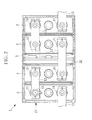
- FIG. 2 is a top plan view which illustrates the inner structure of the battery pack of FIG. 1 .
- the battery pack 1 of this embodiment is a battery pack comprising a plurality of unit cells 2 which are chargeable and dischargeable secondary cells.
- This battery pack 1 is used as a power source of a mobile object such as a deep ocean research vehicle and an electric car, or used for a power storage system, an uninterruptible power supply system, or such applications.
- the battery pack 1 comprises the unit cells 2 such as lithium ion secondary cells, a controller 3 for controlling the unit cells 2, and a cell container 4 in which the unit cells 2 and the controller 3 are placed.
- unit cells 2 such as lithium ion secondary cells
- controller 3 for controlling the unit cells 2
- cell container 4 in which the unit cells 2 and the controller 3 are placed.
- the unit cell 2 is a secondary cell such as a lithium ion secondary cell formed in an approximately rectangular shape.
- the unit cell 2 comprises positive and negative electrode terminals 11 each of which projects in a column shape upward from the top end surface of the unit cell 2 (toward the top of FIG. 1 ).
- the top end surface of each electrode terminal 11 is attached with a crimp terminal 12 which is in an approximately annular-plate-shape and is to be electrically connected to the controller 3, by a fastening member such as a screw.
- FIG. 1 and FIG. 2 show only one crimp terminal 12 for the purpose of easy understanding, and the rest crimp terminals 12 are not shown here.
- a conductive surface of the box of the unit cell 2 is directly exposed.
- the positive and negative electrode terminals 11 of adjacent unit cells 2 are electrically connected by a bus bar 13, which is a connecting bar made of a conductive material.
- the bus bar 13 is a plate-shaped member, in the vicinities of respective ends of which are provided a pair of through holes to insert the electrode terminals 11. With this structure, the electrode terminals 11 are inserted in the through holes of the bus bar 13 before the crimp terminals 12 are attached to the electrode terminals 11. Therefore, the bus bar 13 can be kept from dropping off.
- the description is made with the example where four unit cells 2 are provided to the battery pack 1 and these unit cells 2 are serially connected.
- the number of the unit cells 2 may be greater or smaller than four, and is not specifically limited.
- the controller 3 is to control the voltage or the like while monitoring the voltage and the temperature of the unit cells 2, when the battery pack 1 is being charged or discharged.
- the controller 3 is a control circuit formed on a substrate, and is inserted in a controller chamber 33 in the cell container 4.
- the cell container 4 houses the unit cells 2, the controller 3, and the like, and defines the external shape of the battery pack 1. As shown in FIG. 1 , the cell container 4 comprises a lower case 21 in which the unit cells 2 and the controller 3 are placed, and an upper case 22 which serves as a lid.
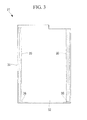
- FIG. 3 is a side elevational view which illustrates the structure of the lower case in the cell container of FIG. 1 .
- FIG. 4 is a top plan view which illustrates the structure of the lower case of FIG. 3 .
- FIG. 5 is a cross-sectional view which illustrates the structure of the lower case of FIG. 4 , taken along the line A-A.
- the lower case 21 is formed of an insulative material such as a resin, and supports the unit cells 2 and the like. As shown in FIG. 3 through FIG.
- the lower case 21 comprises: a case mainframe (package) 31 which is in a rectangular tube shape with a closed bottom and an opened top; and wall portions 34 for partitioning the inside of the case mainframe 31 to define the unit cell chambers 32 and the controller chamber (setup section) 33 in which the unit cells 2 and the controller 3 are placed.
- a case mainframe (package) 31 which is in a rectangular tube shape with a closed bottom and an opened top
- wall portions 34 for partitioning the inside of the case mainframe 31 to define the unit cell chambers 32 and the controller chamber (setup section) 33 in which the unit cells 2 and the controller 3 are placed.
- the unit cell chambers 32 and the controller chamber 33 are aligned side by side, and the controller chamber 33 is sandwiched between the unit cell chambers 32.
- the controller chamber 33 is arranged in the center, and each two unit cell chambers 32 are respectively arranged on the opposite ends of the controller chamber 33.
- the interval between the unit cells 2 which sandwich the controller chamber 33 is widened. Therefore, the heat propagation between these unit cells 2 can be inhibited by this clearance. Therefore, the performance deterioration of the unit cells 2 due to heat generation can be suppressed.
- the unit cell chamber 32 comprises: side ribs (support projections) 35 for supporting the unit cell 2 from the side; and base portions 36 for supporting it from the bottom.
- the side ribs 35 are ribs which project from the wall surfaces of the case mainframe 31 and the wall surfaces of the wall portions 34 in the vicinities of the corners of the unit cell chambers 32 toward the unit cells 2, and extend in the vertical direction. Furthermore, the side ribs 35 also form clearances between the unit cells 2 and the case mainframe 31, and between the unit cells 2 and the wall portions 34. Of these side ribs 35, side ribs 35 provided on the wall portions 34 are formed in approximately cylindrical shapes, in the upper end portions of which are formed screw holes to fix the upper case 22.
- the position to arrange the side ribs 35 is not specifically limited as long as the unit cells 2 can be supported.
- the base portions 36 are plate-shaped members serving as bottoms in the vicinities of the corners of the unit cell chambers 32, and form clearances between the unit cells 2 and the bottom of the case mainframe 31. With this structure, clearances are formed between the bottoms of the unit cells 2 and the bottoms of the unit cell chambers 32, and thereby heat generated in the unit cells 2 can readily radiate.
- a pair of insertion slits 37 for supporting the controller 3 are oppositely arranged.
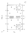
- FIG. 6 is a top plan view which illustrates the structure of the upper case in the cell container of FIG. 1 .
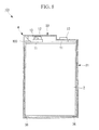
- FIG. 7 is a cross-sectional view which illustrates the structure of the upper case of FIG. 6 , taken along the line B-B.
- the upper case 22 is a lid which defines the external shape of the battery pack 1 by bering attached to the lower case 21, and is formed of an insulative material such as a resin.
- the upper case 22 comprises: a pair of apertures 41 for exposing the electrode terminals 11 of the unit cells 2; screw holes 42 for inserting fastening members such as screws which fix the upper case 22 to the lower case 21; vent holes 43 for communicating between the controller chamber 33 and the outside of the case; and a reinforcing rib 44 for ensuring the rigidity of the upper case 22.
- the unit cells 2 are respectively inserted in the unit cell chambers 32 and are serially connected by using the bus bars 13.
- the controller 3 is inserted in the controller chamber 33, and the electrode terminals 11 of the respective unit cells 2 and the controller 3 are electrically connected.
- the lower case 21 is covered by the upper case 22, and the upper case 22 is fixed to the lower case 21 by fastening members such as screws.
- the unit cells 2 can be placed from the opening into the lower case 21. Furthermore, since the unit cells 2 placed from the opening can be readily accessed, the maintenance of the unit cells 2 and the like can be more readily done.
- the unit cells 2 are supported by the side ribs 35. Therefore, even if the battery pack 1 is vibrated or shocked, the unit cells 2 can be kept from vigorously vibrating or jumping up within the cell container 4. Meanwhile, since the unit cells 2 are supported by the side ribs 35, clearances are formed between the unit cells 2 and the case mainframe 31 and between the unit cells 2 and the wall portions 34. Then, heat generated in the unit cells 2 can radiate into the thus formed clearances, and thereby the performance deterioration of the unit cells 2 due to heat generation can be suppressed. Furthermore, heat propagation between adjacent unit cells 2 can be inhibited by the clearance, and thereby the performance deterioration of the unit cells 2 due to heat generation can be suppressed.
- the wall portions 34 are formed of insulative material(s), it is no longer necessary to form an insulative layer over the surfaces of the unit cells 2. That is to say, since the wall portions 34 and the like can prevent a short-circuit between adjacent unit cells 2, or a short-circuit between the unit cells 2 and an external member, it becomes unnecessary to form an insulative layer over the surfaces of the unit cells 2.
- FIG. 8 is a side cross-sectional view which illustrates the structure of the battery pack according to this embodiment.
- FIG. 9 is a top plan view which illustrates the inner structure of the battery pack of FIG. 8 .
- the same reference symbols are used for components the same as those in the first embodiment, and the description thereof is omitted.
- the battery pack 101 comprises unit cells 2 such as lithium ion secondary cells, a controller 3 for controlling the unit cells 2, a cell container 4 in which the unit cells 2 and the controller 3 are placed, and holddown members 105 for pressing the unit cells 2 down to the cell container 4.
- unit cells 2 such as lithium ion secondary cells
- controller 3 for controlling the unit cells 2
- cell container 4 in which the unit cells 2 and the controller 3 are placed
- holddown members 105 for pressing the unit cells 2 down to the cell container 4.
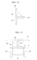
- FIG. 10 is a partially enlarged view which illustrates the structure of the holddown member of FIG. 8 .
- FIG. 11 is a schematic diagram which illustrates the structure of the vicinity of the holddown member of FIG. 8 .
- the holddown member 105 is a member arranged between the upper case 22 and the lower case 21 to press the unit cell 2 down to the lower case 21 while the upper case 22 is being attached to the lower case 21.
- the holddown member 105 comprises an insertion portion 151 to be inserted in a clearance between the unit cell 2 and the lower case 21, an abutting portion 152 to be contacted to the bottom of the upper case 22, and a pressing portion 153 to be contacted to the unit cell 2.
- guide rails 154 for guiding the holddown member 105 is provided on the wall surface of the lower case 21 where the holddown member 105 is arranged.
- the insertion portion 151 and the abutting portion 152 consist of opposite ends of a plate-like member.
- the insertion portion 151 is a part on the unit cell 2 side from the pressing portion 153, and is a part to be inserted into the clearance between the unit cell 2 and the lower case 21.
- the abutting portion 152 is a part on the upper case 22 side from the pressing portion 153, and the top end thereof will be contacted to the upper case 22.
- the pressing portion 153 is a plate-like member which projects at an approximately right angle to the plate-like member which constitutes the insertion portion 151 and the abutting portion 152. Between the pressing portion 153 and the abutting portion 152 is provided a rib for ensuring the rigidity.
- the guide rails 154 are arranged at both sides of the holddown member 105, as well as projecting from the wall surface of the lower case 21 toward the unit cell 2 and extending from the upper case 22 side to the lower case 21 side. Furthermore, the guide rails 154 are configured so as not to interfere with the unit cell 2 to be placed in the unit cell chamber 32, or so as to support the unit cell 2.
- side ribs 35 and the guide rails 154 There are no specific limitations on the side ribs 35 and the guide rails 154. For example, it is possible to separately provide them as mentioned above, or it is also possible to provide only the side ribs 35 by giving the function of the guide rails 154 to the side ribs 35.
- the pressing portions 153 are pressed down to the lower case 21 via the abutting portions 152, and thereby the unit cells 2 are pressed down to the lower case 21. Therefore, the unit cells 2 can be more reliably kept from jumping up. Furthermore, since the insertion portions 151 of the holddown members 105 are inserted into the clearances, the abutting portions 152 abut against a relatively rigid periphery portion of the upper case 22, that is to say, the vicinity of the reinforcing rib 44. Accordingly, the upper case 22 will be less likely deformed, and the unit cells 2 can be more reliably kept from jumping up even if vibrations or shocks are applied due to an external force acting on the battery pack mainframe.
- FIG. 12 is a side cross-sectional view which illustrates the structure of the battery pack according to this embodiment.
- the same reference symbols are used for components the same as those in the first embodiment, and the description thereof is omitted.
- the battery pack 201 comprises unit cells 2 such as lithium ion secondary cells, a controller 3 for controlling the unit cells 2, and a cell container 204 in which the unit cells 2 and the controller 3 are placed.
- the cell container 204 comprises a lower case 21 in which the unit cells 2 and the controller 3 are placed, and an upper case 222 which serves as a lid.
- FIG. 13 is a top plan view which illustrates the structure of the upper case of the cell container of FIG. 12 .
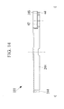
- FIG. 14 is a cross-sectional view which illustrates the structure of the upper case of FIG. 13 , taken along the line C-C.
- the upper case 222 is a lid which defines the external shape of the battery pack 201 by being attached to the lower case 21, and is formed of an insulative material such as a resin.
- the upper case 222 comprises: a pair of apertures 41 for exposing the electrode terminals 11 of the unit cells 2; screw holes 42 for inserting fastening members such as screws which fix the upper case 222 to the lower case 21; vent holes 43 for communicating between the controller chamber 33 and the outside of the case; and a reinforcing rib (raised portion) 244 for ensuring the rigidity of the upper case 222. Furthermore, around the periphery of the aperture 41 is formed a stepped portion 245 which stands out to the lower case 21 side.
- the reinforcing rib 244 is a rib formed in a belt-like shape around the periphery portion of the upper case 222 except for the stepped portions 245, and extending from the upper case 222 towards the lower case 21.
- the reinforcing rib 244 is configured so that the bottom end of the upper case 222 is contacted to the top face of the unit cells 2 when the upper case 222 is attached to the lower case 21.
- the reinforcing rib 244 abuts against the unit cells 2, and thereby the unit cells 2 are pressed down to the lower case 21 side. Therefore, the unit cells 2 can be more reliably kept from jumping up. Furthermore, since the upper case 222 comprises the reinforcing rib 244 which protrudes in a belt-like shape, the rigidity of the upper case 222 is improved as compared to the case without the reinforcing rib 244. Accordingly, the upper case 222 will be less likely deformed, and the unit cells 2 can be more reliably kept from jumping up even if vibrations or shocks are applied due to an external force acting on the battery pack mainframe.
- FIG. 15 is a side cross-sectional view which illustrates the structure of the battery pack according to this embodiment.
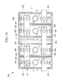
- FIG. 16 is a top plan view which illustrates the inner structure of the battery pack of FIG. 15 .
- the same reference symbols are used for components the same as those in the first embodiment, and the description thereof is omitted.
- the battery pack 301 comprises unit cells 2 such as lithium ion secondary cells, a controller 3 for controlling the unit cells 2, a cell container 4 in which the unit cells 2 and the controller 3 are placed, and first damping sections 305 and second damping sections 306 for damping vibrations.
- unit cells 2 such as lithium ion secondary cells
- controller 3 for controlling the unit cells 2
- cell container 4 in which the unit cells 2 and the controller 3 are placed
- first damping sections 305 and second damping sections 306 for damping vibrations.
- the first damping section 305 and the second damping section 306 are vibration/shock absorbers made of rubber, gel, or such material.
- the first damping sections 305 are approximately plate-like members arranged in the clearances between the lower case 21 and the unit cells 2, and the clearances the between the wall portions 34 and the unit cells 2.
- the first damping section 305 is to alleviate vibrations and shocks transferred from the lower case 21 to the unit cells 2, and vibrations and shocks transferred from the wall portions 34 to the unit cells 2.
- the second damping sections 306 are approximately rectangular members arranged between the upper case 22 and the unit cells 2.
- the second damping section 306 is to alleviate vibrations and shocks transferred from the upper case 22 to the unit cells 2.
- FIG. 17 is a side elevational view which illustrates the structure of the lower case in the battery pack according to this embodiment.
- FIG. 18 is a top plan view which illustrates the structure of the lower case of FIG. 17 .
- FIG. 19 is a cross-sectional view which illustrates the structure of the lower case of FIG. 18 , taken along the line D-D.
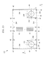
- FIG. 20 is a top plan view which illustrates the structure of the upper case in the battery pack of this embodiment.
- the same reference symbols are used for components the same as those in the first embodiment, and the description thereof is omitted.
- the lower case 421 of the battery pack 401 comprises: a case mainframe (package) 431 which is in a rectangular tube shape with a closed bottom and an opened top; and wall portions 434 for partitioning the inside of the case mainframe 431 and defining the unit cell chambers 32 and the controller chamber 33.
- a case mainframe (package) 431 which is in a rectangular tube shape with a closed bottom and an opened top
- wall portions 434 for partitioning the inside of the case mainframe 431 and defining the unit cell chambers 32 and the controller chamber 33.
- a plurality of first through holes (through holes) 436 are provided in the side walls of the lower case 421, the wall portions 434, and a bottom panel which constitutes one of the unit cell chambers 32 in the lower case 421, that is, either one of the outermost unit cell chambers 32 in this embodiment.
- a plurality of second through holes (through holes) 437 having a smaller diameter than that of the first through hole 436 are provided in the bottom panel which constitutes the controller chamber 33.
- third through holes (through holes) 438 having a smaller diameter than that of the second through hole 437 are provided in the rest of the bottom panels which constitute the other unit cell chambers 32 in the lower case 421.
- a plurality of fourth through holes (through holes) 439 are provided in the area of the upper case 422 except for the stepped portions 245.
- the first through holes 436, the second through holes 437, the third through holes 438, and the fourth through holes 439 may be arranged in zigzag shapes as shown in FIG. 17 through FIG. 20 , or may also be arranged in other patterns without any specific limitations.
- air ventilation can be secured between the clearances and the outside of the upper case 422 and the lower case 421 via the first through holes 436, the second through holes 437, the third through holes 438, and the fourth through holes 439. Therefore, heat generated in the unit cells 2 can more readily radiate as compared to the case without the through holes 436.
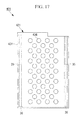
- FIG. 21 is a top plan view which illustrates the structure of the lower case in the battery pack according to this embodiment.
- the same reference symbols are used for components the same as those in the first embodiment, and the description thereof is omitted.
- the lower case 521 of the battery pack 501 comprises: a case mainframe (package) 531 which is in a rectangular tube shape with a closed bottom and an opened top; and wall portions 34 for partitioning the inside of the case mainframe 531 and defining the unit cell chambers 32 and the controller chamber 33.
- a case mainframe (package) 531 which is in a rectangular tube shape with a closed bottom and an opened top
- wall portions 34 for partitioning the inside of the case mainframe 531 and defining the unit cell chambers 32 and the controller chamber 33.
- the wall of the case mainframe 531 which constitute the unit cell chambers 32 comprises side ribs (support projections) 535 for supporting the unit cells 2 from the side.
- the side ribs 535 are formed by folding the wall of the case mainframe 531. These side ribs 535 project toward the unit cells 2 and extend in the vertical direction. According to the abovementioned structure, the rigidity of the lower case 521 can be ensured.
- the position to arrange the side ribs 535 is not specifically limited as long as the unit cells 2 can be supported.
- FIG. 22 is a top plan view which illustrates the inner structure of the battery pack according to this embodiment.
- FIG. 23 is a cross-sectional view which illustrates the inner structure of the battery pack of FIG. 22 , taken along the line E-E.
- the same reference symbols are used for components the same as those in the first embodiment, and the description thereof is omitted.
- the battery pack 601 comprises unit cells 2 such as lithium ion secondary cells, a controller 3 for controlling the unit cells 2, and a cell container 604 in which the unit cells 2 and the controller 3 are placed.
- the cell container 604 comprises a lower case 621 in which the unit cells 2 and the controller 3 are placed, and an upper case 22 which serves as a lid.
- the lower case 621 comprises: a case mainframe (package) 631 which is in a rectangular tube shape with a closed bottom and an opened top; and wall portions 34 for partitioning the inside of the case mainframe 631 and defining the unit cell chambers 32 in which the unit cells 2 are placed.
- a case mainframe (package) 631 which is in a rectangular tube shape with a closed bottom and an opened top
- wall portions 34 for partitioning the inside of the case mainframe 631 and defining the unit cell chambers 32 in which the unit cells 2 are placed.
- the controller 3 is arranged in a space between the upper case 22 and the unit cells 2 placed in the unit cell chambers 32 so that the controller 3 can extend in the direction along which the unit cells 2 are arranged. According to the abovementioned structure, it is not necessary to separately secure the space to store the controller 3. Therefore, the size of the cell container 604 can be reduced.
Landscapes
- Chemical & Material Sciences (AREA)
- Chemical Kinetics & Catalysis (AREA)
- Electrochemistry (AREA)
- General Chemical & Material Sciences (AREA)
- Engineering & Computer Science (AREA)
- Manufacturing & Machinery (AREA)
- Microelectronics & Electronic Packaging (AREA)
- Materials Engineering (AREA)
- Battery Mounting, Suspending (AREA)
Applications Claiming Priority (2)
| Application Number | Priority Date | Filing Date | Title |
|---|---|---|---|
| JP2008051042A JP5330712B2 (ja) | 2008-02-29 | 2008-02-29 | 電池収納容器および組電池 |
| PCT/JP2009/053037 WO2009107557A1 (ja) | 2008-02-29 | 2009-02-20 | 電池収納容器および組電池 |
Publications (2)
| Publication Number | Publication Date |
|---|---|
| EP2249414A1 true EP2249414A1 (de) | 2010-11-10 |
| EP2249414A4 EP2249414A4 (de) | 2013-04-10 |
Family
ID=41015954
Family Applications (1)
| Application Number | Title | Priority Date | Filing Date |
|---|---|---|---|
| EP09714482.8A Withdrawn EP2249414A4 (de) | 2008-02-29 | 2009-02-20 | Zellenbehälter und batterie |
Country Status (6)
| Country | Link |
|---|---|
| US (1) | US20100196749A1 (de) |
| EP (1) | EP2249414A4 (de) |
| JP (1) | JP5330712B2 (de) |
| KR (1) | KR101207088B1 (de) |
| CN (1) | CN101933176A (de) |
| WO (1) | WO2009107557A1 (de) |
Cited By (2)
| Publication number | Priority date | Publication date | Assignee | Title |
|---|---|---|---|---|
| DE102011011238A1 (de) | 2011-02-15 | 2012-08-16 | Li-Tec Battery Gmbh | Gehäuse zur Aufnahme einer flachen elektrochemischen Zelle |
| US9548476B2 (en) | 2010-12-20 | 2017-01-17 | Samsung Sdi Co., Ltd. | Multi-cell battery module with integral cooling and assembly aids |
Families Citing this family (27)
| Publication number | Priority date | Publication date | Assignee | Title |
|---|---|---|---|---|
| JP2011159597A (ja) * | 2010-02-03 | 2011-08-18 | Toshiba Corp | 組電池 |
| KR101441423B1 (ko) | 2010-09-01 | 2014-10-20 | 에스케이이노베이션 주식회사 | 일체형 전지 연결 장치가 구비되는 고전압 배터리 |
| JP2012221881A (ja) * | 2011-04-13 | 2012-11-12 | Ydk:Kk | 深海用群電池ユニット、およびセルの電圧値を均等化させる方法、並びにプログラム |
| WO2013054727A1 (ja) * | 2011-10-13 | 2013-04-18 | 株式会社ケーヒン | 電源制御装置 |
| JP5648621B2 (ja) * | 2011-11-14 | 2015-01-07 | 株式会社デンソー | 組電池 |
| US8962177B2 (en) * | 2011-12-09 | 2015-02-24 | Samsung Sdi Co., Ltd. | Secondary battery |
| JP6107114B2 (ja) | 2012-01-16 | 2017-04-05 | 株式会社Gsユアサ | 電源装置 |
| KR101278229B1 (ko) | 2012-04-24 | 2013-06-24 | 이응재 | 2차전지 팩키지용 통합모듈 장치 |
| JP5687260B2 (ja) * | 2012-11-07 | 2015-03-18 | 本田技研工業株式会社 | 蓄電装置および蓄電装置の車両搭載構造 |
| DE102013203280A1 (de) * | 2013-02-27 | 2014-08-28 | Bayerische Motoren Werke Aktiengesellschaft | Hochvolt-Energiespeichermodul und Verfahren zur Herstellung des Hochvolt-Energiespeichermoduls |
| JP6146093B2 (ja) * | 2013-03-29 | 2017-06-14 | 株式会社Gsユアサ | 蓄電装置 |
| JP6135246B2 (ja) | 2013-03-29 | 2017-05-31 | 株式会社Gsユアサ | 蓄電装置 |
| US10381614B2 (en) | 2013-04-17 | 2019-08-13 | Samsung Sdi Co., Ltd. | Battery module |
| JP2015018790A (ja) | 2013-06-14 | 2015-01-29 | 株式会社Gsユアサ | 蓄電モジュール |
| JP6236902B2 (ja) * | 2013-06-14 | 2017-11-29 | 株式会社Gsユアサ | 蓄電装置 |
| KR101729213B1 (ko) * | 2013-10-23 | 2017-04-21 | 주식회사 엘지화학 | 진동 특성이 향상된 배터리 모듈 및 이에 적용되는 프레임 카트리지 조립체 |
| JP6201870B2 (ja) * | 2014-04-07 | 2017-09-27 | 株式会社Gsユアサ | 蓄電装置 |
| WO2015186849A1 (ko) * | 2014-06-03 | 2015-12-10 | 삼성에스디아이 주식회사 | 전지 트레이 |
| JP6363418B2 (ja) * | 2014-07-30 | 2018-07-25 | 株式会社Gsユアサ | 蓄電装置 |
| CN104300098A (zh) * | 2014-10-10 | 2015-01-21 | 浙江新大力电光源集团股份有限公司 | 一种抗振的蓄电池外壳 |
| DE102015212241A1 (de) * | 2015-06-30 | 2017-01-05 | Robert Bosch Gmbh | Batteriesubmodul und Batteriesystem |
| JP6685761B2 (ja) * | 2016-02-19 | 2020-04-22 | 株式会社Gsユアサ | 蓄電装置 |
| AU2016204458B2 (en) * | 2016-03-07 | 2018-02-22 | Kabushiki Kaisha Toshiba | Battery module |
| US10950884B2 (en) | 2016-06-22 | 2021-03-16 | Faraday & Future Inc. | Battery assembly processes |
| JP7017398B2 (ja) * | 2017-12-18 | 2022-02-08 | 住友ナコ フォ-クリフト株式会社 | バッテリアッセンブリ及び荷役作業車 |
| DE102018219468A1 (de) * | 2018-11-14 | 2020-05-14 | Audi Ag | Hochstromkomponentenverbindungsanordnung, Batterieanschlussbox, Hochvoltbordnetz, Kraftfahrzeug und Verfahren zum Verbinden zweier Hochstromkomponenten |
| KR102497913B1 (ko) * | 2018-12-12 | 2023-02-09 | 주식회사 엘지에너지솔루션 | 전지셀의 보관 케이스 및 이를 포함하는 보관 장치 |
Family Cites Families (15)
| Publication number | Priority date | Publication date | Assignee | Title |
|---|---|---|---|---|
| JP2002025516A (ja) * | 2000-07-03 | 2002-01-25 | Toshiba Battery Co Ltd | 電池パック |
| JP2002134078A (ja) * | 2000-10-26 | 2002-05-10 | Toyota Motor Corp | 集合電池パック |
| JP4186413B2 (ja) * | 2000-11-21 | 2008-11-26 | 新神戸電機株式会社 | 電池モジュール |
| ES2193849B1 (es) * | 2001-07-31 | 2005-03-01 | S.E. Acumulador Tudor, S.A. | Bateria de acumuladores electricos. |
| JP3848565B2 (ja) * | 2001-11-27 | 2006-11-22 | 松下電器産業株式会社 | 電池間接続構造および電池モジュール並びに電池パック |
| JP4308515B2 (ja) * | 2002-12-27 | 2009-08-05 | パナソニック株式会社 | 電池モジュール |
| JP4362321B2 (ja) * | 2003-06-13 | 2009-11-11 | パナソニック株式会社 | 組電池 |
| JP4961695B2 (ja) | 2004-10-22 | 2012-06-27 | 日産自動車株式会社 | 組電池および組電池の組み立て方法 |
| KR20060037598A (ko) * | 2004-10-28 | 2006-05-03 | 삼성에스디아이 주식회사 | 전지 모듈 |
| US7989104B2 (en) * | 2004-10-28 | 2011-08-02 | Samsung Sdi Co., Ltd. | Battery module |
| JP5227494B2 (ja) * | 2005-06-02 | 2013-07-03 | 株式会社東芝 | 組電池の電池パック |
| JP2007018754A (ja) * | 2005-07-05 | 2007-01-25 | Gs Yuasa Corporation:Kk | 組電池 |
| JP2007018752A (ja) * | 2005-07-05 | 2007-01-25 | Gs Yuasa Corporation:Kk | 組電池 |
| WO2007047809A2 (en) * | 2005-10-19 | 2007-04-26 | Railpower Technologies Corp. | Design of a large low maintenance battery pack for a hybrid locomotive |
| JP4448111B2 (ja) * | 2006-07-31 | 2010-04-07 | 日立ビークルエナジー株式会社 | 電源システム |
-
2008
- 2008-02-29 JP JP2008051042A patent/JP5330712B2/ja not_active Expired - Fee Related
-
2009
- 2009-02-20 KR KR1020107006586A patent/KR101207088B1/ko not_active Expired - Fee Related
- 2009-02-20 CN CN2009801005419A patent/CN101933176A/zh active Pending
- 2009-02-20 US US12/678,402 patent/US20100196749A1/en not_active Abandoned
- 2009-02-20 EP EP09714482.8A patent/EP2249414A4/de not_active Withdrawn
- 2009-02-20 WO PCT/JP2009/053037 patent/WO2009107557A1/ja not_active Ceased
Cited By (3)
| Publication number | Priority date | Publication date | Assignee | Title |
|---|---|---|---|---|
| US9548476B2 (en) | 2010-12-20 | 2017-01-17 | Samsung Sdi Co., Ltd. | Multi-cell battery module with integral cooling and assembly aids |
| DE102011011238A1 (de) | 2011-02-15 | 2012-08-16 | Li-Tec Battery Gmbh | Gehäuse zur Aufnahme einer flachen elektrochemischen Zelle |
| WO2012110204A2 (de) | 2011-02-15 | 2012-08-23 | Li-Tec Battery Gmbh | Gehäuse zur aufnahme einer flachen elektrochemischen zelle |
Also Published As
| Publication number | Publication date |
|---|---|
| US20100196749A1 (en) | 2010-08-05 |
| JP5330712B2 (ja) | 2013-10-30 |
| EP2249414A4 (de) | 2013-04-10 |
| KR20100057876A (ko) | 2010-06-01 |
| CN101933176A (zh) | 2010-12-29 |
| JP2009211835A (ja) | 2009-09-17 |
| WO2009107557A1 (ja) | 2009-09-03 |
| KR101207088B1 (ko) | 2012-11-30 |
Similar Documents
| Publication | Publication Date | Title |
|---|---|---|
| EP2249414A1 (de) | Zellenbehälter und batterie | |
| US11545727B2 (en) | Easier to assemble battery module including bus bar frame | |
| US11342621B2 (en) | Battery pack | |
| EP2816633B1 (de) | Energiespeichervorrichtung | |
| KR20190064887A (ko) | 방열 플레이트를 구비한 배터리 모듈 | |
| EP2615662B1 (de) | Stromquelleneinheit mit einem elektrischen Bauteil | |
| CN114784433B (zh) | 可再充电电池包 | |
| KR20170056973A (ko) | 이차 전지 모듈 | |
| KR20070112489A (ko) | 중대형 전지모듈 | |
| TWI814743B (zh) | 具有電池限制器的電池組 | |
| KR101750487B1 (ko) | 외부 입출력 단자 및 버스 바의 장착 수단을 포함하는 전지모듈 | |
| EP3780287B1 (de) | Batteriemodul mit konnektor mit stossabsorbierender struktur | |
| KR102655770B1 (ko) | 배터리 팩 및 이러한 배터리 팩을 포함하는 자동차 | |
| KR20130042430A (ko) | 배터리 모듈 및 이를 포함하는 중·대형 배터리 모듈 | |
| KR102760922B1 (ko) | 배터리, 전기기기 및 배터리의 제조 방법 | |
| JP7154382B2 (ja) | バッテリーパック及びそれを含む自動車 | |
| CN103430348A (zh) | 蓄电装置 | |
| KR20200002327U (ko) | 전지 스택용 스페이서 및 전지 스택을 포함하는 전지 모듈 | |
| JP2023504557A (ja) | バッテリーパック及びそれを含む自動車 | |
| KR20230078513A (ko) | 배터리 모듈, 이를 포함하는 배터리 팩 및 에너지 저장 장치 | |
| KR102555927B1 (ko) | 배터리, 전기 설비, 배터리의 제조 방법 및 제조 설비 | |
| JP7603710B2 (ja) | バッテリーモジュール、それを含むバッテリーパック及び自動車 | |
| JP7241291B2 (ja) | 電池モジュールおよび電池パック | |
| JP7518109B2 (ja) | 電池パック | |
| KR20210104491A (ko) | 배터리 모듈, 이러한 배터리 모듈을 포함하는 배터리 팩 및 자동차 |
Legal Events
| Date | Code | Title | Description |
|---|---|---|---|
| PUAI | Public reference made under article 153(3) epc to a published international application that has entered the european phase |
Free format text: ORIGINAL CODE: 0009012 |
|
| 17P | Request for examination filed |
Effective date: 20100325 |
|
| AK | Designated contracting states |
Kind code of ref document: A1 Designated state(s): AT BE BG CH CY CZ DE DK EE ES FI FR GB GR HR HU IE IS IT LI LT LU LV MC MK MT NL NO PL PT RO SE SI SK TR |
|
| AX | Request for extension of the european patent |
Extension state: AL BA RS |
|
| DAX | Request for extension of the european patent (deleted) | ||
| A4 | Supplementary search report drawn up and despatched |
Effective date: 20130311 |
|
| RIC1 | Information provided on ipc code assigned before grant |
Ipc: H01M 2/10 20060101AFI20130305BHEP Ipc: H01M 2/02 20060101ALI20130305BHEP Ipc: H01M 2/20 20060101ALI20130305BHEP Ipc: H01M 2/34 20060101ALI20130305BHEP Ipc: H01M 10/50 20060101ALI20130305BHEP Ipc: H01M 10/42 20060101ALI20130305BHEP Ipc: H01M 10/04 20060101ALI20130305BHEP |
|
| 17Q | First examination report despatched |
Effective date: 20131106 |
|
| STAA | Information on the status of an ep patent application or granted ep patent |
Free format text: STATUS: THE APPLICATION IS DEEMED TO BE WITHDRAWN |
|
| 18D | Application deemed to be withdrawn |
Effective date: 20141031 |