EP2249447A2 - Dispositif de raccordement - Google Patents
Dispositif de raccordement Download PDFInfo
- Publication number
- EP2249447A2 EP2249447A2 EP10157080A EP10157080A EP2249447A2 EP 2249447 A2 EP2249447 A2 EP 2249447A2 EP 10157080 A EP10157080 A EP 10157080A EP 10157080 A EP10157080 A EP 10157080A EP 2249447 A2 EP2249447 A2 EP 2249447A2
- Authority
- EP
- European Patent Office
- Prior art keywords
- cable support
- arrangement according
- connection
- recess
- fastening means
- Prior art date
- Legal status (The legal status is an assumption and is not a legal conclusion. Google has not performed a legal analysis and makes no representation as to the accuracy of the status listed.)
- Withdrawn
Links
- 230000000295 complement effect Effects 0.000 claims description 5
- 238000004519 manufacturing process Methods 0.000 description 3
- 238000005452 bending Methods 0.000 description 1
- 230000015572 biosynthetic process Effects 0.000 description 1
- 230000008878 coupling Effects 0.000 description 1
- 238000010168 coupling process Methods 0.000 description 1
- 238000005859 coupling reaction Methods 0.000 description 1
- 238000005304 joining Methods 0.000 description 1
- 239000002184 metal Substances 0.000 description 1
- 238000010079 rubber tapping Methods 0.000 description 1
- 238000009827 uniform distribution Methods 0.000 description 1
Images

Classifications
-
- H—ELECTRICITY
- H02—GENERATION; CONVERSION OR DISTRIBUTION OF ELECTRIC POWER
- H02G—INSTALLATION OF ELECTRIC CABLES OR LINES, OR OF COMBINED OPTICAL AND ELECTRIC CABLES OR LINES
- H02G3/00—Installations of electric cables or lines or protective tubing therefor in or on buildings, equivalent structures or vehicles
- H02G3/02—Details
- H02G3/06—Joints for connecting lengths of protective tubing or channels, to each other or to casings, e.g. to distribution boxes; Ensuring electrical continuity in the joint
- H02G3/0608—Joints for connecting non cylindrical conduits, e.g. channels
-
- H—ELECTRICITY
- H02—GENERATION; CONVERSION OR DISTRIBUTION OF ELECTRIC POWER
- H02G—INSTALLATION OF ELECTRIC CABLES OR LINES, OR OF COMBINED OPTICAL AND ELECTRIC CABLES OR LINES
- H02G3/00—Installations of electric cables or lines or protective tubing therefor in or on buildings, equivalent structures or vehicles
- H02G3/02—Details
- H02G3/04—Protective tubing or conduits, e.g. cable ladders or cable troughs
- H02G3/0437—Channels
Definitions
- the invention relates to a connection arrangement for connecting cable support elements, in particular cable trays, cable trays, cable ducts or the like, with at least two cable support elements, wherein the cable support members each have complementary connection areas in a connecting portion, which can be arranged overlapping, wherein a first connection region at least one fastening means for fastening the first connection area at a second connection area.
- connection arrangements of the aforementioned type are used in particular for connecting cable trays, cable trays, cable channels or the like to a cable support system, as can be used, for example, for the laying of large amounts of cable in buildings.
- the cable support members forming the cable support system are mounted on a suitable support structure on a wall, floor or ceiling and fitted with the cables to be laid.
- the cable support elements are regularly made of metal or plastic and are with prefabricated through holes in the form of slots or Holes provided, which essentially serve as an assembly aid or for the diversion of cables.
- the cable support elements are connected at their longitudinal ends by means of suitable fastening means as fastening means are, for example, couplings, screws, connecting straps or the like are used.
- fastening means which are already arranged on a cable support member, so that when assembling the cable support members, the cable support members can lock together.
- fastening means which are already arranged on a cable support member, so that when assembling the cable support members, the cable support members can lock together.
- the sole formation of a latching connection is not satisfactory, since this is not sufficiently stable and safe against unintentional release, for example, a screw.
- the intended for this purpose fasteners have to be specially designed for the respective cable support elements or for the type of connection, that is, it can not be resorted to standardized and thus in large quantities inexpensive available fasteners.
- the present invention is therefore based on the object to propose a connection arrangement which allows a simple mounting of cable support members without specially trained fastener, the connection assembly should still be formed stably.
- At least two cable support elements of the connection arrangement according to the invention for connecting cable support elements have complementary connection areas in a connection section, which can be arranged overlapping, wherein a first connection area has at least one fastening means for fastening the first connection area to a second connection area, the second connection area having at least one recess , which is arranged on the second connection region, that the fastening means by a relative movement of the cable support members transversely and longitudinally to a longitudinal axis of a cable support member in the recess is positively inserted.
- the fastening means is already preassembled on a cable support member, so that it requires only one assembly of the cable support members by the aforementioned relative movement for mounting. Since the connection regions of the cable support elements are designed to overlap complementarily, the cable support elements are already largely fixed by the merging in their intended mounting position. The shape of the recess defined by the relative movement of the two cable support elements ensures that the cable support elements can not be unintentionally pulled apart without further ado, for example by movement relative to the longitudinal axis. The so spent in their mounting position cable support elements are now sufficiently secure mountable by means of the fastener, without the need for a special, manual fixing the position of the cable support members relative to each other. The connection arrangement thus secures against unintentional loosening and allows in a simple, self-explanatory manner an intentional release of the connection, wherein no special tool for the disassembly / assembly is needed.
- connection regions can be formed such that the second connection region engages around the first connection region on its outer surface facing away from a support receptacle.
- the first connection area can then be formed in accordance with a cross-sectional profile of the cable support member in question, so that it only requires a deviating from the cross-sectional profile training of the second connection area.
- the cable support elements used for the connection arrangement can then be produced particularly inexpensively.
- the recess arranged on the second connection region is L-shaped. In this way, an unintentional pulling apart of the cable support elements in one direction can be effectively avoided, since the L-shaped recess for a unilaterally directed relative movement forms a stop for the fastening means.
- the connection arrangement can as far as possible prevent the uncontrolled solution of the cable support elements in both the vertical and horizontal directions.
- an opening region of the recess is formed transversely to the longitudinal axis of the cable supporting element.
- the cable support members can then be joined together during assembly so that the fastening means is inserted from above or below the recess in this. Accordingly, a cable support members with the fastener or a cable support member with the recess in an already mounted cable support member with a complementary connection area are simply hung before a relative movement along the longitudinal axis of the cable support elements. On a further, manual alignment or fixation of the cable support members relative to each other can thus be dispensed with, which further simplifies assembly.
- An assembly of the cable support elements is further simplified when an opening portion of the recess is funnel-shaped.
- the cable support elements must then no longer be aligned or positioned exactly relative to each other at the beginning of the assembly, since the funnel-shaped opening area when merging can correct position deviations.
- connection arrangement can be produced particularly easily.
- the fastening means and the recess may be provided on side walls of the respective U-shaped profile cross sections.
- This arrangement can further simplify assembly, especially since the side walls are particularly well accessible for a person to be mounted. Also, a laying of the cable on a bottom wall of the profile cross sections is then not affected by the type of attachment.
- connection areas are designed so that a frictional connection can be formed.
- An in addition to the positive connection formed frictional connection effectively prevents any relative movement that could be possible in the context of an engagement game of the connection areas in the positive connection.
- the connection regions could then be designed such that a connection can be formed in the manner of an interference fit formed by the connection regions.
- the fastening means may be a screw.
- the screw can then serve on the one hand for producing a positive connection with the recess and on the other hand for non-positive attachment of the connecting portions.
- the screw can be used, for example, in a thread formed in a connection region or designed as a tapping screw, which is partially screwed into a simple passage opening of a connection region. In the context of a machine production process, placement of screws, Nuts, setting nuts and / or a creation of a threaded thread with threaded thread completed.
- a nut is provided as a further fastening means.
- a high surface pressure between the connection areas can be achieved, which results in a high fastening force.
- connection arrangement can be further improved in that a connection region forms at least one deformable fastening means.
- the deformable fastening means can be deformed after joining the connecting regions so that a further positive connection between the connecting regions is formed. As a result, unintentional release of the connection arrangement can be avoided, since the deformable attachment means then serves as a backup.
- a connecting region forms at least one further recess into which the deformable fastening means can engage, it is ensured that the connecting regions are positioned in their relative position provided for a connection.
- the deformable fastener can be made particularly easily if the deformable fastener is a tab.
- the deformable attachment means and the further recess may each be provided in a bottom wall of the cable support members.
- connection arrangement can be securely formed if at least two attachment means or recesses are provided for each connection region.
- the fastening means or recesses may be arranged symmetrically to the longitudinal axes of the cable support members on the cable support members, so that an easy handling and a uniform distribution of forces acting on the connection arrangement forces can be achieved.
- first and the second connection region are formed on a cable support element.
- a cable support system may then be formed from a plurality of similar cable support members.
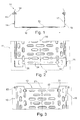
- the Fig . 1 to 3 show a first cable support member 10 in a profile cross section and a second cable support member 11 and the first cable support member 10 shown in sections in a plan view.
- the first cable support element 10 has a first connection region 12, which is designed to be complementary to a second connection region 13 of the second cable support element 11.
- the first connection region 12 corresponds to a profile cross-section 14 of the cable support elements 10 and 11 and has two fasteners designed as screws 15 with nuts 16.
- the nuts 16 are disposed on side walls 17 of the first cable support member 10 and the first connection portion 12, respectively, so that the screws 15 can be preassembled as shown.
- the second connection region 13 is designed such that it can embrace the first connection region 12 on an outer surface 18.
- the second connection region 13 further has deformable fastening means formed as tabs 21 in a bottom wall 22.
- the tabs 21 are deformable along a longitudinal axis 23 of the first cable support element 10.
- recesses 25 are formed in the tabs 21 are used by deformation. In a connection arrangement, not shown here, the tabs thus deformed can prevent the connection arrangement from being pulled apart.
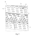
- a synopsis of Fig. 4 to 7 shows an assembly of the first cable support member 10 with the second cable support member 11 to a connection assembly 26.
- the first cable support member 10 is, as in Fig. 4 shown, relative to the second cable support member 11 so arranged that the screw 15 is aligned with a funnel-shaped opening 27 of the L-shaped recess 20.
- the cable support members 10 and 11 respectively according to the arrows 28 along the axis 29 and transversely to the longitudinal axes 23 and 30 of the cable support members 10 and 11 are moved so that, as in Fig. 5 illustrated, the screw 15 is inserted into the recess 20.
- the respective longitudinal axes 23 and 30 of the cable support elements 10 and 11 are now aligned, so that as shown in FIG Fig.
- the cable support members 10 and 11 and their connecting portions 12 and 13 are pushed into each other according to the arrows 31.
- the screw 15 is then moved accordingly in a longitudinal groove 32 of the recess 20. Accordingly, the cable support members 10 and 11 are positively connected so that they can not be separated by a unidirectional movement in the direction of arrows 28 or 31.
- the screws 15 are connected to the nuts 16 so that a frictional connection between the first connection portion 12 and the second connection portion 13 is formed.
- the tabs 21 are in the connection arrangement 26 shown here in a covering position to the recesses 25, so that a bending of the tabs 21 in the recesses 25 is made possible.
- the non-positive connection should solve, in particular allows the L-shaped configuration of the recess 20 securing the connection assembly 26, since at least one separating movement along the longitudinal axes 23 and 30 of the cable support members 10 and 11 and along the axis 29th transverse to the longitudinal axes 23 and 30 is necessary to completely separate the cable support members 10 and 11.
Landscapes
- Engineering & Computer Science (AREA)
- Architecture (AREA)
- Civil Engineering (AREA)
- Structural Engineering (AREA)
- Installation Of Indoor Wiring (AREA)
Applications Claiming Priority (1)
| Application Number | Priority Date | Filing Date | Title |
|---|---|---|---|
| DE202009006602U DE202009006602U1 (de) | 2009-05-07 | 2009-05-07 | Verbindungsanordnung |
Publications (2)
| Publication Number | Publication Date |
|---|---|
| EP2249447A2 true EP2249447A2 (fr) | 2010-11-10 |
| EP2249447A3 EP2249447A3 (fr) | 2014-04-30 |
Family
ID=40984444
Family Applications (1)
| Application Number | Title | Priority Date | Filing Date |
|---|---|---|---|
| EP10157080.2A Withdrawn EP2249447A3 (fr) | 2009-05-07 | 2010-03-19 | Dispositif de raccordement |
Country Status (2)
| Country | Link |
|---|---|
| EP (1) | EP2249447A3 (fr) |
| DE (1) | DE202009006602U1 (fr) |
Cited By (1)
| Publication number | Priority date | Publication date | Assignee | Title |
|---|---|---|---|---|
| WO2013015755A2 (fr) | 2011-06-13 | 2013-01-31 | Kiraç Metal Ürünleri̇ San. Ve Ti̇c. Ltd. | Chemin de câbles à encliquetage facile sans moyen de connexion |
Families Citing this family (2)
| Publication number | Priority date | Publication date | Assignee | Title |
|---|---|---|---|---|
| TR200908738A2 (tr) * | 2009-11-18 | 2010-05-21 | Kiraç Metal Ürünleri̇ San. Ve Ti̇c. Ltd. Şti̇. | Yüksek dayanım gücüne sahip kolay geçmeli kablo taşıma kanalları ve kanalların birleştirilmesine ilişkin yöntem |
| CN102713390A (zh) | 2009-11-18 | 2012-10-03 | 基拉克金属制品工贸有限公司 | 电缆桥架 |
Family Cites Families (4)
| Publication number | Priority date | Publication date | Assignee | Title |
|---|---|---|---|---|
| DE8102851U1 (de) * | 1981-02-04 | 1982-07-22 | OBO Bettermann oHG, 5750 Menden | Kabelbahn als Träger von elektrischen Kabeln |
| US7762042B2 (en) * | 2007-04-29 | 2010-07-27 | Cooper Technologies Company | Wireway quick-connect system |
| DE202008009852U1 (de) * | 2008-07-23 | 2008-09-18 | Niedax Gmbh & Co. Kg | Kabelrinne |
| CN102713390A (zh) * | 2009-11-18 | 2012-10-03 | 基拉克金属制品工贸有限公司 | 电缆桥架 |
-
2009
- 2009-05-07 DE DE202009006602U patent/DE202009006602U1/de not_active Expired - Lifetime
-
2010
- 2010-03-19 EP EP10157080.2A patent/EP2249447A3/fr not_active Withdrawn
Non-Patent Citations (1)
| Title |
|---|
| None |
Cited By (1)
| Publication number | Priority date | Publication date | Assignee | Title |
|---|---|---|---|---|
| WO2013015755A2 (fr) | 2011-06-13 | 2013-01-31 | Kiraç Metal Ürünleri̇ San. Ve Ti̇c. Ltd. | Chemin de câbles à encliquetage facile sans moyen de connexion |
Also Published As
| Publication number | Publication date |
|---|---|
| DE202009006602U1 (de) | 2009-08-20 |
| EP2249447A3 (fr) | 2014-04-30 |
Similar Documents
| Publication | Publication Date | Title |
|---|---|---|
| DE102013203166B4 (de) | Bowdenzug | |
| EP2614563B1 (fr) | Bâti pour systèmes de passe-câbles et pièces pour ce bâti | |
| DE102010048029B4 (de) | Ausrichteinrichtung | |
| EP3796482B1 (fr) | Connecteur enfichable comprenant un pont conducteur de protection | |
| EP4239233B1 (fr) | Demi-écrou et procédé d'assemblage d'un demi-écrou | |
| DE202007013238U1 (de) | Befestigungshülse zum Aufstecken auf einen Gewindebolzen | |
| DE102009048153A1 (de) | Profilelement und Verfahren zum Herstellen eines Profilelements | |
| DE102010033849B4 (de) | Halteclip und Baugruppe mit Halteclip und Rastelement | |
| EP2249447A2 (fr) | Dispositif de raccordement | |
| EP3690155A1 (fr) | Dispositif de robinetterie | |
| EP3092687A1 (fr) | Outil de montage pour libérer un élément d'encliquetage d'une prise mâle qui est relié à une prise femelle par encliquetage, élément de tête d'un outil de montage et procédé de libération d'une prise mâle reliée à une prise femelle par encliquetage | |
| DE202010010424U1 (de) | Wanddurchführungsklemme für elektrische Leiter | |
| EP2403084B1 (fr) | Guidage de câble et de conduite | |
| DE102020126444B4 (de) | Leitungsdurchführung mit einem Grundrahmen und mit einer Mehrzahl an Leitungsdurchführungsmodulen sowie Verfahren zu deren Montage | |
| DE102010002634B4 (de) | Befestigungsanordnung für Kabelführungen | |
| DE102014118499B4 (de) | Schelle zur Befestigung einer Leitung, insbesondere stromführenden Leitung, an einem Schienenfahrzeug | |
| EP3954838A1 (fr) | Système d'éléments de raccordement pour profilés plats à installer au niveau du sol dans des cellules sanitaires | |
| EP2639911B1 (fr) | Elément de montage pour canaux d'intégration d'appareils, canal d'intégration d'appareils doté d'un tel élément de montage et procédé de montage d'un tel élément de montage dans un canal d'intégration d'appareils | |
| EP1609223A1 (fr) | Dispositif pour fixer un cable sur une surface | |
| DE102014018493A1 (de) | Clipartiges Positionierungselement für Kabel | |
| EP3850254A1 (fr) | Traversée murale pour câbles | |
| DE10355631B4 (de) | Befestigungselement | |
| DE102013105047B4 (de) | Anordnung zum Befestigen einer Schiene | |
| DE102013003631B3 (de) | Halter zum Fixieren einer Leitung, insbesondere eines Rohres, sowie entsprechende Verbindungsanordnung | |
| DE102009040131B3 (de) | Befestigungslasche für ein Schutzzaunfeld |
Legal Events
| Date | Code | Title | Description |
|---|---|---|---|
| PUAI | Public reference made under article 153(3) epc to a published international application that has entered the european phase |
Free format text: ORIGINAL CODE: 0009012 |
|
| AK | Designated contracting states |
Kind code of ref document: A2 Designated state(s): AT BE BG CH CY CZ DE DK EE ES FI FR GB GR HR HU IE IS IT LI LT LU LV MC MK MT NL NO PL PT RO SE SI SK SM TR |
|
| AX | Request for extension of the european patent |
Extension state: AL BA ME RS |
|
| PUAL | Search report despatched |
Free format text: ORIGINAL CODE: 0009013 |
|
| AK | Designated contracting states |
Kind code of ref document: A3 Designated state(s): AT BE BG CH CY CZ DE DK EE ES FI FR GB GR HR HU IE IS IT LI LT LU LV MC MK MT NL NO PL PT RO SE SI SK SM TR |
|
| AX | Request for extension of the european patent |
Extension state: AL BA ME RS |
|
| RIC1 | Information provided on ipc code assigned before grant |
Ipc: H02G 3/06 20060101AFI20140321BHEP |
|
| STAA | Information on the status of an ep patent application or granted ep patent |
Free format text: STATUS: THE APPLICATION IS DEEMED TO BE WITHDRAWN |
|
| 18D | Application deemed to be withdrawn |
Effective date: 20141031 |