EP2249464B1 - Couvercle pour un boîtier de connection d'un moteur électrique - Google Patents
Couvercle pour un boîtier de connection d'un moteur électrique Download PDFInfo
- Publication number
- EP2249464B1 EP2249464B1 EP10007950.8A EP10007950A EP2249464B1 EP 2249464 B1 EP2249464 B1 EP 2249464B1 EP 10007950 A EP10007950 A EP 10007950A EP 2249464 B1 EP2249464 B1 EP 2249464B1
- Authority
- EP
- European Patent Office
- Prior art keywords
- lid
- motor
- phase motor
- box
- motor according
- Prior art date
- Legal status (The legal status is an assumption and is not a legal conclusion. Google has not performed a legal analysis and makes no representation as to the accuracy of the status listed.)
- Expired - Lifetime
Links
Images



Classifications
-
- H—ELECTRICITY
- H02—GENERATION; CONVERSION OR DISTRIBUTION OF ELECTRIC POWER
- H02K—DYNAMO-ELECTRIC MACHINES
- H02K5/00—Casings; Enclosures; Supports
- H02K5/04—Casings or enclosures characterised by the shape, form or construction thereof
- H02K5/22—Auxiliary parts of casings not covered by groups H02K5/06-H02K5/20, e.g. shaped to form connection boxes or terminal boxes
- H02K5/225—Terminal boxes or connection arrangements
-
- H—ELECTRICITY
- H02—GENERATION; CONVERSION OR DISTRIBUTION OF ELECTRIC POWER
- H02K—DYNAMO-ELECTRIC MACHINES
- H02K11/00—Structural association of dynamo-electric machines with electric components or with devices for shielding, monitoring or protection
- H02K11/30—Structural association with control circuits or drive circuits
- H02K11/33—Drive circuits, e.g. power electronics
Definitions
- Bus systems are known to the person skilled in the art, in particular fieldbus systems such as INTERBUS, PROFIBUS, DeviceNet, CAN bus, AS-i or even LON, EIB and other wireless systems.
- a motor switching stage which is installed in the motor connection box of an electric motor.
- the disadvantage here is that the electric motor can only be switched on or off.
- a soft start is not feasible.
- a soft start stage detects a higher heat output in some operating states than a simple electronic switching stage DE 197 39 780 on. The cooling specified there is not sufficient for a circuit with higher heat output.
- An electric motor with frequency converter is known, wherein a terminal box replacement intermediate part is provided.
- the inverter is provided in a cover which is electrically connectable by means of a connector to the motor.
- the cover is placed on the intermediate part when connecting, thus closing off the motor connection box.
- the lid thus has an electrical and mechanical interface for placing on the intermediate part.
- the intermediate part surrounds connection devices for power supply lines.
- the invention has the object of developing a three-phase motor while avoiding the aforementioned disadvantages.
- the cover should be inexpensive to manufacture and easily be replaced in case of errors or assembly.
- parts should be reusable as often as possible.
- the object is achieved in a three-phase motor according to the features indicated in claim 1.
- the three-phase motor is provided with a motor junction box and a box comprising a base and a lid mounted thereon to form the box.
- the cover comprising an electronic circuit for electrically influencing the three-phase motor, comprising power electronics and control electronics and a programmable logic and / or memory, such as EEPROM, wherein the electronic circuit comprises connection devices for transmitting information, and wherein the lid has an electrical and mechanical interface for placing on the lower part of the box and on other different parts, wherein the motor connection box of the three-phase motor has a connector part, and wherein the lower part comprises connection devices for power supply lines, and wherein the lower part has an electrical connector part for electrical connection to the connector part of the motor junction box, wherein forming a plug connection from the connector part and the connector part of the box, comprising the lower part and the cover, is mounted on a plate connected to the motor terminal box and releasably connected , wherein the plate relieves the connector, wherein the lid is connected by means
- the advantage here is that by the electronic circuit wear-free influencing the electric motor, such as switching on and off, soft start and error control or the like, executable and when replacement of the electronic circuit, for example in case of defect, assembly or retrofitting, the exchange quickly , easy and inexpensive to carry out.
- the lid can be placed by its interface even on other parts that are spatially far away from the engine positionable. These further parts can be formed in such a way that together with the cover they form a device which can be formed such that it substantially fulfills the function of the motor connection box comprising the cover and an intermediate part of a motor connection box.
- the electronic circuit is used to electrically influence an electric motor and this is a star-connected asynchronous motor.
- these motors are inexpensive to produce and are widely used in industry.
- to influence such motors consuming converters are necessary, which can not be accommodated for industry in services such as 0.5 kW to 100kW in a lid.
- Even if only switching on and off is necessary, costly, expensive wear-prone contactors are required.
- the invention provides a simple, inexpensive and wear-free cover with an electronic circuit for influencing the motor.
- the lid is inexpensive, fast, and easily replaceable.
- the electronic circuit has a converter for converting transmitted or transmitted information, in particular EIB, LON, AS-i, fieldbus, Interbus, Profibus, CAN bus, infrared or radio transmission, to digital inputs / outputs and the lid for this purpose corresponding connection devices.
- the lid thus fulfills the additional function of a decentralized control module and offers the bus system access to sensors and actuators.
- the motor is dependent on sensors, in particular of inductive sensors or light barriers, controllable, as can be switched on or off or the like.
- the electrical connector of the lower part is directly connectable to the motor terminal box on a connector having electric motor by plugging.
- the separate box can be connected to the motor connection box and plugged directly into it.
- the separate box is installable at a great distance from the engine. In this way, a concept for wiring is advantageously provided which is uniform and at the same time compatible with industry standards, in particular for connectors bearing motors, such as DESINA ®, or motors with manufacturer-dependent structure of the motor connection box.
- an electrical connector is the only electrical connection between the cover and the intermediate part with the exception of a connection to the ground. It is particularly advantageous that the production, installation or repair is particularly simple and quick to carry out.
- the first thermal barrier and / or second thermal barrier is designed such that it also represents a seal in high degree of protection and / or represent, such as a seal against the contact corrosion, ingress of dirt, dust, liquids and / or water or like. It is particularly advantageous that the thermal barrier combines several functions in itself and therefore parts can be saved.
- the first thermal barrier and / or second thermal barrier made of rubber, plastic and / or plastic or the like. It is particularly advantageous that a cost-effective material is used.
- the lid comprises at least one device for exchanging information. It is particularly advantageous that the state of an electric motor of other, even distant devices, such as a central computer, converters or the like, can be influenced and the possibility of a feedback of the state to these other devices can be realized.
- the exchange of information by modulation of electromagnetic waves with or without a carrier medium feasible, such as modulated radio waves, modulated infrared radiation, modulated electrical currents in electrical conductors or the like. It is particularly advantageous that electromagnetic waves can spread widely and therefore information with distant devices even wirelessly interchangeable.
- the exchange of information via lines for fieldbus in particular INTERBUS, PROFIBUS, CAN bus, AS-i or the like, feasible, the information being encoded in a corresponding bus protocol, and wherein the lines for fieldbus to the motor junction box to lead. It is advantageous that a compatible industry standard is available.
- the lid has an electronic circuit comprising power electronics and control electronics. It is advantageous that the at least two parts can be built separately and thermally separated from each other, in particular by means of a thermal barrier.
- the power electronics of the electronic circuit on so many electronic circuit breaker that even a reversal of rotation is executable via a switching on, off and soft start.
- a cover without reversal functionality is therefore replaceable by a cover with such.
- the power electronics to the housing part of the lid towards a lower heat transfer resistance than the housing of the intermediate part and / or as to the housing of the electric motor. It is advantageous that the power electronics can be thermally separated or isolated from the motor housing and the heat is dissipated through the lid to the environment.
- the electric motor can be operated in star connection and the power electronics comprises electronic circuit breakers and is designed such that the star point can be separated or closed. It is advantageous that with a few circuit breakers, in particular a single, the electric motor is disconnected from the network.
- the power switches are designed as thyristors or the like.
- the circuit breaker can be controlled with a phase control, wherein the voltages on the motor windings from zero to a value is variable. It is advantageous that the rms value of the voltage, which develops over a network period, can be varied and / or influenced.
- the lid has at least one input means, in particular two potentiometers, wherein the time profile of the voltage at the motor windings can be influenced. It is advantageous that in a simple manner by the operator on the voltage curve on the electric motor can be influenced.
- a starting torque can be influenced by means of a first input means and / or the time duration until reaching a voltage value can be influenced by means of a second input means. It is advantageous that each input means an influencing variable can be assigned.
- At least one temperature sensor for detecting the temperature of the electronic circuit breaker with the circuit breakers thermally conductively connected and electrically connectable to the control electronics. It is advantageous that the electric motor or its power electronics can be switched off when a first critical temperature is exceeded.
- At least one further temperature sensor for detecting the temperature of at least one winding of the electric motor is thermally conductively connected to the control electronics and electrically connectable. It is advantageous that the electric motor can be switched off when a second critical temperature is exceeded.
- the lid has a Peltier element, which is connected to the power electronics with a very low heat transfer resistance. It is advantageous that the heat dissipation from the power electronics is improved out and for cooling a wear-free device is used.
- the lid can be manufactured in a high degree of protection because the Peltier elements do not require a ventilation slot.
- the cover has active cooling elements, such as fans or the like. It is advantageous that the heat dissipation from the power electronics is improved out, with standard systems can be used.
- the lid may have ventilation slots in one embodiment. In another embodiment, it is executed over a large area and the active cooling elements whirl air or a cooling medium in a closed space around and thus bring this to a certain temperature level. Thus, the large area is used for heat dissipation.
- the cover has at least one bypass relay or the like to relieve the semiconductor electronics. It is advantageous that the semiconductors are short-circuited and therefore produce less heat.
- the lid (3) is electrically connected by means of a connector with the intermediate part (2).
- the lid has a line to ground the lid. This grounding line is connected to the intermediate part.
- the electronic circuit in the cover (3) of the motor connection box has control and power electronics.
- the power electronics include electronic circuit breakers that deliver their heat to the housing part of the lid (3).
- electronic circuit breakers thyristors are used.
- other power switches are used or instead of the connector only power cable between the cover part (3) and intermediate part (2) used for electrical connection.
- FIG. 1 is by means of electronic circuit breaker, the electric motor off and on.
- a first temperature sensor is thermally connected to the circuit breakers.
- the first temperature sensor is connected to the mounting surface, but has a very low heat transfer resistance to the electronic circuit breakers;
- the first temperature sensor is thermally connected to the circuit breakers.
- Electrically, the first temperature sensor is connected to the electronic circuit. Therefore, with a strong increase in the temperature of the circuit breaker for safety reasons, the electronic circuit can be switched off.
- the value of the temperature and / or a corresponding error message via the device for exchanging information to another device, such as a central computer and / or a decentralized control module, further reported.
- a second temperature sensor is thermally conductively connected to the windings in the electric motor and electrically connected to the control electronics. Likewise, this allows a reporting of exceeding a critical temperature value to other devices. It also allows a safety shutdown. Depending on the type of system and the security concept used there, the options are used or not used.
- the electronic circuit on the cover (3) in FIG. 2 is different from the one in FIG. 1 shown lids; it has a control circuit comprising a device for phase control of the thyristors.
- a first input means (7) and as a second input means (8) a potentiometer is used in each case. In this way, the motor voltage or its rms value can be brought to values between zero and mains voltage in a variable manner.
- the first input means (7) advantageously influences the starting value of the voltage - and thus also the starting value of the torque - and the second input means (8) influences the time duration until reaching an end value, in particular this is the rms value of the mains voltage.
- the lid off FIG. 1 is interchangeable with the lid off FIG. 2 ,
- the functionality of an electric motor according to the invention can be changed quickly and inexpensively in the field in a simple manner.
- the lid is off FIG. 1 and also the lid off FIG. 2 each also in different versions equipped.
- covers are produced which have a Profibus-compatible control electronics, and covers are made which have an INTERBUS-compatible control electronics.
- the electric motor can be made with motor terminal box and then provided with a customer-appropriate cover.
- other covers are manufactured with correspondingly different functionality.
- the electric motors with a motor connection box and cover thus form a series.
- a first exemplary representative of this series is in FIG. 1 shown.
- a second exemplary representative is in FIG. 2 shown.
- covers are manufactured with various devices for exchanging information.
- the electronic circuit is designed such that electromagnetic signals are modulated onto the power cables.
- it is possible to work with a carrier frequency of 200 kHz by way of example.
- modulated electromagnetic radio waves are used for transmission.
- the lid has an effective as an antenna element, in particular, this function can also be taken over by parts that already exist anyway, such as electrical cables, housing parts or the like, or which are specially designed and designed for this purpose.
- modulated infrared radiation is used to transmit the information.
- the intermediate part and / or cover has corresponding components.
- infrared semiconductors such as diodes and / or transistors for transmitting and / or receiving infrared radiation or the like, are attached to the motor junction box, in particular on its lid, or connected to the lid.
- bypass relays are used to relieve the electronic circuit breakers, such as thyristors or the like.
- the control electronics controls the bypass relay when a certain period of time has passed after switching on or a certain motor voltage, in particular mains voltage, is reached.
- the bypass relays then close the electronic circuit breakers and thereby relieve them. It also reduces energy consumption.
- Lids with different cooling systems are interchangeable.
- a lid without special cooling system is thus interchangeable with a lid with a more efficient cooling system. This is particularly advantageous if it is determined that the cooling capacity used is insufficient initially.
- corners, edges, protrusions, protrusions or the like are provided on the lid and / or on the intermediate part to prevent interchangeable ones whose software and / or hardware does not match the given motor configuration.
- the engine configuration includes engine power, type of engine, such as number of poles or the like, or the presence of additional components, such as a brake, a fan, a temperature sensor or the like.
- the mechanical interface of the lid to the intermediate part is therefore designed in this example in such a way that there is security for the connection with regard to the electrical operation.
- the mechanical interface is designed in such a way with said corners, edges, etc., that the lid is twisted not be placed.
- a protection against reverse polarity, direction reversal or the like is achieved.
- FIG. 3 is shown for an example power electronics (31) which can be influenced by the control electronics (32) and in which the star point of the electric motor u 2 v 2 w 2 by means of electronic circuit breakers of the power electronics (31) connectable. Temperature sensors are not shown in this figure.
- the uncontrolled rectifier bridge (40) is connected to the star point side terminals of the electric motor.
- the control electronics (32) influences the drive unit (41), which in turn influences the electronic power switch (44).
- the drive unit (41) is supplied via the power supply device (42).
- a measuring device (43) supplies the control electronics (32) with information or signals about the voltages and / or phase angles of the network phases.
- the measuring device (43) supplies the Control electronics (32) also with energy.
- sensors such as temperature sensors or the like, can be connected to the control electronics (32).
- a temperature sensor which monitors the temperature of the power electronics, in particular the electronic circuit breaker. If a critical temperature is exceeded then switching off the electronics is executable. Also useful is a temperature sensor which monitors the temperature of the windings of the stator of the electric motor. When a further critical temperature is exceeded turn off the electronics and / or the electric motor can be executed.
- the controlled rectifier bridge (50) is connected to the star point side terminals of the electric motor. It comprises thyristors in the illustrated embodiment.
- the control electronics (32) influence the drive unit (41) such that a phase control of the thyristors is executable.
- the rms value of the voltage can be reduced to a value lower than the net rms value.
- the voltage of zero volts can be brought within a certain time to a certain value.
- the electric motor starts more gently, so with less jerk.
- the electric motor is suitable for the respective mechanical application to interpret.
- the time constants of this startup can be influenced via input means, such as potentiometers or input keys or the like.
- input means such as potentiometers or input keys or the like.
- the starting value of the voltage thus also the torque during starting, can be influenced and the time duration until reaching the desired voltage value can be influenced by means of a second input means.
- the convergence or end value of the effective value of the voltage can be influenced by a third input means.
- the heat production of the power electronics is permanently increased.
- the electronic circuit has repeaters for bus or bus-like systems, such as interfaces, AS-i or the like.
- the electronic circuit can be designed in such a way that the mentioned values which can be influenced by input means can be influenced by means of data transmission.
- data is transmitted via bus or bus-like systems in such a way that they are influenced by the input means Values can be influenced without such input means.
- they are stored by the electronic circuit, so that they remain even after switching off and on the electronic circuit or the whole system.
- the electronic circuit has EEPROM for this purpose.
- bypass relays can be used to relieve the electronic circuit breaker. These short the semiconductor switches after reaching the convergence or end value of the RMS value of the voltage, relieve them and therefore also reduce the heat production of the power electronics.
- an exemplary timing waveform is shown using a phase gating controller for an antiparallel arranged thyristor pair to provide a substantially resistive load.
- the thyristor is switched from the blocking to the conducting state.
- the thyristor is again blocking.
- the antiparallel thyristor is treated in a similar way. The procedure is repeated at grid frequency and therefore has the same periodicity as the grid.
- the effective voltage achievable over a network period ranges from zero volts to the rms value of the mains voltage.
- FIG. 7 an example voltage waveform is shown using a phase gating controller for an antiparallel arranged thyristor pair.
- the ignition of the thyristors is not regularly repeated at mains frequency.
- the ignition of a thyristor is followed by fewer and fewer power half periods during which no ignition takes place. After some time, however, is ignited at regular intervals, in particular net periodic. It is brought so to speak, the instantaneous frequency value of 0 Hz at mains frequency. In the manner described, therefore, not only the effective value but also a value similar to a frequency value can be changed.
- this is in the FIG. 7 shown method advantageous.
- a frequency of a fraction of the network frequency is permanently achievable.
- the electric motor can by omitting two ignition events of the FIG. 6 can be easily operated with one third of the mains frequency.
- FIG. 5 replaced all three diodes by driven by the drive unit (41) thyristors.
- the drive unit (41) thyristors By phase control of the type described then other end frequencies or other soft-start modes are realized.
- the voltage and / or frequency can be varied finely.
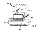
- the electric motor (1) with an intermediate part (2), the connecting devices, in particular a terminal block, for the power lines (83).
- the operating mode can be set in star / delta mode.
- the power lines (83) are guided through the PG gland (85) in the intermediate part (2).
- the PG gland (85) is designed as a quick disconnect connector.
- the lid (3) is drawn in a slightly raised position.
- the star point is not, as usual, short-circuited, but with the three power lines (82) led to the lid (3).
- connection to connectors is used instead of the power lines (82).
- the cover (3) has a connection for AS-i.
- the electronic circuit comprises a converter, which receives its power supply from the AS-i bus and provides the data of the bus of the remaining signal electronics of the electronic circuit.
- the lid (3) also has at least one potentiometer (84).
- the ramps of the soft start can be influenced, that is, the starting value of the voltage, the time behavior of the voltage curve, and / or the end value of the voltage.
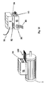
- FIG. 9 an electric motor (1) having a closed motor connection box (91) Connector or connector part (94) shows.
- DESINA® industry standard. Such standards were created to make engines easily and quickly connectable or exchangeable. With these DESINA® industrial standard motors, all motor winding connections are transferred to the connector part. Thus, in a large plant with many drives, they significantly reduce installation, installation and maintenance costs.
- the connector part (94) designed as a socket and the connector part (93) as a plug. Alternatively , plug and socket are reversed for safety reasons.
- the bottom part (92) of the box has a PG gland (94) for the power lines (83) for power supply.
- the PG gland is replaced by a connector with connector parts.
- the power supply can be disconnected quickly on the network side.
- the lid (3) is in the FIG. 9 according to the FIG. 8 connected to the lower part (92), since the interface of the lid (3) is carried out electrically and mechanically similar.
- power lines (82) from the lid (3) to the lower part (92) shown which are replaced in another example by a plug connection.
- the lid (3) designed with connectors can be mounted both on a lower part (92) of a box, as in FIG FIG. 9 shown, as well as on a suitable intermediate part (2) of a motor connection box to be placed. Due to the versatility, the lid can be produced in large quantities.
- a wiring concept has been created which can be used in particular in large systems, wherein the electric motors are controllable via a bus system.
- the installation, installation and maintenance costs can be significantly reduced.
- the electric motors start smoothly and the exact startup behavior is even adjustable.
- the startup behavior can be influenced even from the central computer.
- a plate (100) is shown, to which the box, comprising the lower part 92 and the lid (3), is attachable and detachably connectable.
- the connector part (94) and the connector part (93) are thus less loaded and can also be used in applications with strong Rüttelschwingungen.
Landscapes
- Engineering & Computer Science (AREA)
- Power Engineering (AREA)
- Microelectronics & Electronic Packaging (AREA)
- Motor Or Generator Frames (AREA)
Claims (13)
- Moteur à courant triphasé (1) avec un boîtier de jonction de moteur (91) et un boîtier comprenant une partie inférieure (92) et un couvercle (3) posé dessus pour former le boîtier,
le couvercle (3) comprenant un circuit électronique permettant d'influencer électriquement le moteur à courant triphasé (1), qui comprend une électronique de puissance, une électronique de commande et une logique programmable et/ou une mémoire comme une EEPROM,
le circuit électronique comprenant des dispositifs de connexion pour la transmission d'informations,
et le couvercle présentant une interface électrique et mécanique pour la pose sur la partie inférieure (92) du boîtier et sur d'autres parties (2, 92) de différentes sortes,
le boîtier de jonction de moteur du moteur à courant triphasé (1) présentant une partie de connecteur enfichable (94),
et la partie inférieure (92) présentant des dispositifs de connexion pour des lignes d'alimentation en énergie (83),
et la partie inférieure (92) présentant une partie de connecteur enfichable électrique (93) pour la liaison électrique avec la partie de connecteur enfichable (94) du boîtier de jonction de moteur (91), le boîtier comprenant la partie inférieure (92) et le couvercle (3) étant posé sur une plaque (100) reliée au boîtier de jonction de moteur et étant relié à celle-ci de manière amovible en formant une connexion enfichable composée de la partie de connecteur enfichable (94) et de la partie de connecteur enfichable (93), la plaque (100) déchargeant la connexion enfichable,
le couvercle (3) étant relié au moyen d'une partie de connecteur enfichable électrique à une partie de connecteur enfichable correspondante se trouvant dans la partie inférieure (92). - Moteur à courant triphasé selon la revendication 1,
caractérisé en ce que
le moteur à courant triphasé (1) est un moteur asynchrone qui peut fonctionner en couplage en étoile. - Moteur à courant triphasé selon la revendication 1,
caractérisé en ce que
la partie inférieure (92) présente au moins trois lignes électriques (82) pour courant fort vers le couvercle (3), qui sont reliées de façon amovible. - Moteur à courant triphasé selon au moins l'une des revendications précédentes,
caractérisé en ce que
la partie inférieure (92) présente au moins trois lignes électriques (82) pour courant fort vers le couvercle (3), qui sont reliées de façon amovible. - Moteur à courant triphasé selon la revendication 4,
caractérisé en ce que
le connecteur enfichable électrique de la partie inférieure (92) peut être relié au moteur électrique (1) présentant une partie de connecteur enfichable (94) sur son boîtier de jonction de moteur (91) au moyen d'un câble présentant des parties de connecteur enfichable correspondantes à ses extrémités. - Moteur à courant triphasé selon la revendication 4,
caractérisé en ce que
la partie de connecteur enfichable électrique (93) de la partie inférieure (92) peut être reliée directement au moteur électrique (1) présentant une partie de connecteur enfichable (94) sur son boîtier de jonction de moteur (91) par enfichage. - Moteur à courant triphasé selon au moins l'une des revendications précédentes,
caractérisé en ce que
la partie inférieure (92) présente une première barrière thermique vers le boîtier de moteur et le couvercle (3) présente une deuxième barrière thermique vers l'autre partie. - Moteur à courant triphasé selon au moins l'une des revendications précédentes,
caractérisé en ce que
le circuit électronique présente une plus faible résistance de transfert thermique vers le couvercle (3) du boîtier de jonction de moteur (91) que vers le boîtier de moteur. - Moteur à courant triphasé selon au moins l'une des revendications précédentes,
caractérisé en ce que
la première barrière thermique et/ou la deuxième barrière thermique est/sont réalisée(s) de façon qu'elle(s) constitue(nt) aussi un joint à haut degré de protection, comme un joint contre la pénétration de poussière, de saleté, de liquides et/ou d'eau ou analogues. - Moteur à courant triphasé selon au moins l'une des revendications précédentes,
caractérisé en ce que
la première barrière thermique et/ou la deuxième barrière thermique est/sont réalisée(s) en caoutchouc, plastique et/ou matière synthétique ou analogue. - Moteur à courant triphasé selon au moins l'une des revendications précédentes,
caractérisé en ce que
le couvercle (3) comprend au moins un dispositif pour l'échange d'informations. - Moteur à courant triphasé selon au moins l'une des revendications précédentes,
caractérisé en ce que
l'électronique de puissance présente une plus faible résistance de transfert thermique vers la partie boîtier du couvercle (3) que vers le boîtier de la partie inférieure (92) et/ou vers le boîtier du moteur électrique (1). - Moteur à courant triphasé selon au moins l'une des revendications précédentes,
caractérisé en ce que
le circuit électronique présente un convertisseur pour convertir une information transmise ou à transmettre par EiB ou LON en entrées/sorties numériques et le couvercle (3) présente à cet effet des dispositifs de connexion correspondants.
Applications Claiming Priority (2)
| Application Number | Priority Date | Filing Date | Title |
|---|---|---|---|
| DE19957064.7A DE19957064B4 (de) | 1999-11-26 | 1999-11-26 | Deckel |
| EP00123518A EP1104080A3 (fr) | 1999-11-26 | 2000-10-27 | Couvercle pour un boítier de connection d'un moteur électrique |
Related Parent Applications (2)
| Application Number | Title | Priority Date | Filing Date |
|---|---|---|---|
| EP00123518.3 Division | 2000-10-27 | ||
| EP00123518A Division EP1104080A3 (fr) | 1999-11-26 | 2000-10-27 | Couvercle pour un boítier de connection d'un moteur électrique |
Publications (3)
| Publication Number | Publication Date |
|---|---|
| EP2249464A2 EP2249464A2 (fr) | 2010-11-10 |
| EP2249464A3 EP2249464A3 (fr) | 2013-07-24 |
| EP2249464B1 true EP2249464B1 (fr) | 2014-12-10 |
Family
ID=7930500
Family Applications (3)
| Application Number | Title | Priority Date | Filing Date |
|---|---|---|---|
| EP10007950.8A Expired - Lifetime EP2249464B1 (fr) | 1999-11-26 | 2000-10-27 | Couvercle pour un boîtier de connection d'un moteur électrique |
| EP07021406.9A Expired - Lifetime EP1895642B1 (fr) | 1999-11-26 | 2000-10-27 | Moteur à courant alternatif |
| EP00123518A Ceased EP1104080A3 (fr) | 1999-11-26 | 2000-10-27 | Couvercle pour un boítier de connection d'un moteur électrique |
Family Applications After (2)
| Application Number | Title | Priority Date | Filing Date |
|---|---|---|---|
| EP07021406.9A Expired - Lifetime EP1895642B1 (fr) | 1999-11-26 | 2000-10-27 | Moteur à courant alternatif |
| EP00123518A Ceased EP1104080A3 (fr) | 1999-11-26 | 2000-10-27 | Couvercle pour un boítier de connection d'un moteur électrique |
Country Status (2)
| Country | Link |
|---|---|
| EP (3) | EP2249464B1 (fr) |
| DE (1) | DE19957064B4 (fr) |
Families Citing this family (27)
| Publication number | Priority date | Publication date | Assignee | Title |
|---|---|---|---|---|
| DE10142751B4 (de) * | 2000-12-20 | 2012-04-12 | Sew-Eurodrive Gmbh & Co. Kg | Vorrichtung bei einem Antrieb und Verfahren für die Vorrichtung |
| DE10228863B4 (de) * | 2002-06-27 | 2019-10-31 | Sew-Eurodrive Gmbh & Co Kg | Anlage |
| DE102004027744A1 (de) * | 2004-06-07 | 2005-12-22 | Wilo Ag | Elektromotor mit Elektronikkasten |
| US7229301B2 (en) * | 2005-04-25 | 2007-06-12 | Hilti Aktiengesellschaft | Motor-switch arrangement for a hand-held power tool |
| DE102005042599B4 (de) * | 2005-09-07 | 2024-12-19 | Sew-Eurodrive Gmbh & Co Kg | System, Antrieb und Verfahren zur Herstellung und/oder Inbetriebnahme eines Antriebs |
| DE102006051371B4 (de) * | 2005-10-28 | 2021-06-02 | Sew-Eurodrive Gmbh & Co Kg | Antrieb mit Elektromotor |
| EP1943744B1 (fr) | 2005-10-28 | 2012-06-27 | SEW-EURODRIVE GmbH & Co. KG | Dispositif d'insertion d'un module avec transmission d'énergie et/ou de données sans contact |
| DE102006031389A1 (de) * | 2006-07-07 | 2008-01-10 | Danfoss Bauer Gmbh | Anschlußleitung |
| DE102007052445B4 (de) | 2006-12-20 | 2024-02-01 | Sew-Eurodrive Gmbh & Co Kg | System |
| DE102007027895A1 (de) | 2007-06-18 | 2008-12-24 | Robert Bosch Gmbh | Trennrelais sowie Verfahren zum Betreiben eines Trennrelais |
| ATE467940T1 (de) * | 2007-09-26 | 2010-05-15 | Ebm Papst Mulfingen Gmbh & Co | Elektromotor |
| DE102007046674A1 (de) | 2007-09-27 | 2009-04-09 | Ksb Aktiengesellschaft | Haltevorrichtung für eine Kreiselpumpenanordnung |
| DE102008000145A1 (de) * | 2008-01-25 | 2009-07-30 | Zf Friedrichshafen Ag | Anordnung zum Ansteuern eines Drehstromantriebes |
| DE202008003624U1 (de) | 2008-03-13 | 2009-08-06 | Weidmüller Interface GmbH & Co. KG | Anschlussvorrichtung für Elektromotoren |
| DE102009033185B4 (de) * | 2009-05-13 | 2014-12-31 | Avl Software And Functions Gmbh | Ladesystem und Ladeverfahren zum Laden einer Batterie eines Fahrzeugs und Fahrzeug mit einem solchen Ladesystem |
| DE102009050232B4 (de) | 2009-10-21 | 2011-09-22 | Sew-Eurodrive Gmbh & Co. Kg | Elektrogerät |
| FR2961360B1 (fr) * | 2010-06-11 | 2013-05-24 | Axoris | Dispositif applicatif integre dans une structure mecanique motorisee |
| CH703538B1 (de) * | 2010-07-15 | 2014-10-15 | Bms Britschgi Motorschutzschalter | Gehäuse für Stern-Dreieck-Motorschutzschalter mit verschiebbaren Befestigungslöchern. |
| DE102010044143A1 (de) | 2010-11-18 | 2012-05-24 | Lq Mechatronik-Systeme Gmbh | Motoranschlusskasten und Drehstrommotor |
| GB2483524B (en) | 2011-01-27 | 2012-08-08 | Protean Electric Ltd | A switch arrangement |
| DE102011050719B4 (de) * | 2011-05-30 | 2016-06-02 | Lti Reenergy Gmbh | Notbetriebsfähige Drehstrommotor-Antriebsschaltung |
| DE102013011299A1 (de) * | 2013-07-08 | 2015-01-08 | Sew-Eurodrive Gmbh & Co Kg | Antrieb, umfassend eine Antriebskomponente, insbesondere Elektromotor oder Getriebe |
| DE102015100502B4 (de) * | 2015-01-14 | 2023-11-30 | Cayago Tec Gmbh | Unterwasser-Antriebs-Einheit |
| DE102017202989A1 (de) * | 2017-02-23 | 2018-08-23 | Baumüller Nürnberg GmbH | Umrichter |
| DE102019004761A1 (de) * | 2019-07-05 | 2021-01-07 | Ziehl-Abegg Se | Elektromotor mit einem Rotor und einem Stator |
| EP4066360B1 (fr) | 2019-11-25 | 2026-03-25 | Sew-Eurodrive GmbH & Co. KG | Systeme avec moteur electrique et transmission des donnees des capteurs |
| US20230301007A1 (en) * | 2020-02-12 | 2023-09-21 | Sew-Eurodrive Gmbh & Co. Kg | Electrical device, in particular converter or converter motor, having a cover part and signal electronics |
Family Cites Families (17)
| Publication number | Priority date | Publication date | Assignee | Title |
|---|---|---|---|---|
| US4642607A (en) * | 1985-08-06 | 1987-02-10 | National Semiconductor Corporation | Power line carrier communications system transformer bridge |
| FR2634332B1 (fr) | 1988-07-13 | 1993-02-12 | Salmson Pompes | Moteur electrique equipe d'un moyen de jonction modulaire |
| IT1255190B (it) | 1992-06-30 | 1995-10-20 | Giuseppe Marchisi | Dispositivo di interfaccia di comando per un motore elettrico |
| DE4442867C2 (de) | 1994-12-02 | 1999-09-09 | Mannesmann Sachs Ag | Antriebsanordnung für ein Fahrzeug, insbesondere ein Straßenfahrzeug |
| DE59509098D1 (de) | 1994-12-08 | 2001-04-19 | Siemens Ag | Vorrichtung zur störsicheren modulation und demodulation von analogen signalen zur nachrichtenübertragung über die schirmungen von energieübertragungskabeln |
| FR2732523B1 (fr) * | 1995-04-03 | 1997-04-25 | Schneider Electric Sa | Module d'interface entre un bus de terrain et un appareillage electrique de commande et de protection d'un moteur electrique |
| JP3646741B2 (ja) * | 1995-06-27 | 2005-05-11 | 株式会社荏原電産 | インバータ駆動ポンプの制御システム |
| DE19704226B4 (de) * | 1997-02-05 | 2004-09-30 | Sew-Eurodrive Gmbh & Co. Kg | Klemmdeckelumrichter |
| DE19704801C2 (de) | 1997-02-08 | 1999-04-29 | Phoenix Contact Gmbh & Co | Netzbetriebener Elektromotor |
| JPH10248199A (ja) * | 1997-02-28 | 1998-09-14 | Toshiba Corp | インバータユニット付きモータ、モータ取付用インバータユニット並びにインバータユニット取付用モータ |
| FR2763180B1 (fr) * | 1997-05-09 | 1999-06-04 | Schneider Electric Sa | Procede et appareil de commande d'un depart-moteur communiquant avec un bus |
| JPH1118372A (ja) * | 1997-06-27 | 1999-01-22 | Hitachi Ltd | 永久磁石式回転子を有する電動機 |
| JP3688853B2 (ja) * | 1997-07-03 | 2005-08-31 | 株式会社日立産機システム | 制御装置一体型電動機 |
| DE19739780B4 (de) | 1997-09-10 | 2007-03-22 | Sew-Eurodrive Gmbh & Co. Kg | Drehstrommotor |
| JPH11155257A (ja) * | 1997-11-20 | 1999-06-08 | Toshiba Corp | インバータユニット付きモータ |
| JP3310215B2 (ja) * | 1998-03-20 | 2002-08-05 | アスモ株式会社 | 車載エアコンドア駆動装置 |
| DE19816170C5 (de) | 1998-04-09 | 2004-09-23 | Sew-Eurodrive Gmbh & Co | Steuerungsmodul |
-
1999
- 1999-11-26 DE DE19957064.7A patent/DE19957064B4/de not_active Expired - Lifetime
-
2000
- 2000-10-27 EP EP10007950.8A patent/EP2249464B1/fr not_active Expired - Lifetime
- 2000-10-27 EP EP07021406.9A patent/EP1895642B1/fr not_active Expired - Lifetime
- 2000-10-27 EP EP00123518A patent/EP1104080A3/fr not_active Ceased
Also Published As
| Publication number | Publication date |
|---|---|
| DE19957064B4 (de) | 2020-06-18 |
| EP2249464A3 (fr) | 2013-07-24 |
| EP1895642A3 (fr) | 2012-04-11 |
| EP1104080A3 (fr) | 2002-08-28 |
| DE19957064A1 (de) | 2001-06-13 |
| EP1104080A2 (fr) | 2001-05-30 |
| EP2249464A2 (fr) | 2010-11-10 |
| EP1895642B1 (fr) | 2014-01-15 |
| EP1895642A2 (fr) | 2008-03-05 |
Similar Documents
| Publication | Publication Date | Title |
|---|---|---|
| EP2249464B1 (fr) | Couvercle pour un boîtier de connection d'un moteur électrique | |
| EP2692216B1 (fr) | Ensemble convertisseur, procédé pour fabriquer un ensemble convertisseur et procédé pour faire fonctionner un ensemble convertisseur | |
| EP1675249B1 (fr) | Moteur électrique | |
| DE112010002696T5 (de) | Antriebsvorrichtung | |
| EP0994559B1 (fr) | Convertisseur | |
| DE3642724A1 (de) | Elektromotor mit einem frequenzumrichter zur steuerung der motorbetriebsgroessen | |
| DE112010002702T5 (de) | Antriebsvorrichtung | |
| DE112010002715T5 (de) | Antriebsvorrichtung | |
| DE102014114615A1 (de) | Wicklungssystem | |
| EP1237260A2 (fr) | Moteur à convertisseur et gamme de système d'entraínement | |
| AT17880U1 (de) | Umrichter | |
| DE9305174U1 (de) | Drehstrom-Asynchronmotor mit Frequenzumrichter | |
| EP1362405B1 (fr) | Dispositif de reglage pour un moteur | |
| DE19908045C2 (de) | Kabelsystem, umfassend Kabel zur Verkabelung mindestens eines Umrichters mit Elektromotor | |
| EP0437696B1 (fr) | Dispositif de connexion commuable à distance | |
| EP3462591A1 (fr) | Convertisseur modulaire et système convertisseur modulaire | |
| DE3340198C2 (fr) | ||
| DE10206107A1 (de) | Umrichter und Verwendung | |
| WO1997048178A1 (fr) | Dispositif a moteur commute electroniquement | |
| DE102013006730A1 (de) | Anlage mit Anschlusseinheit, Elektromotor und Motorsteuereinheit und Kabel | |
| WO2016135336A1 (fr) | Moteur à courant continu/générateur à réglage de puissance intégré, et circuit de commande pour moteur à courant continu | |
| DE10228863B4 (de) | Anlage | |
| EP2088669A2 (fr) | Dispositif et méthode pour la mise en oeuvre des machines à courant alternatif monophasé ou à courant triphasé pour traiter le mortier | |
| DE19964437B4 (de) | Verteiler | |
| DE10040285C2 (de) | Verfahren zur Begrenzung des Drehmoments und zur Einstellung der Leerlaufdrehzahl eines Elektromotors in Sternpunktschaltung und eine Vorrichtung |
Legal Events
| Date | Code | Title | Description |
|---|---|---|---|
| PUAI | Public reference made under article 153(3) epc to a published international application that has entered the european phase |
Free format text: ORIGINAL CODE: 0009012 |
|
| AC | Divisional application: reference to earlier application |
Ref document number: 1104080 Country of ref document: EP Kind code of ref document: P |
|
| AK | Designated contracting states |
Kind code of ref document: A2 Designated state(s): AT BE CH CY DE DK ES FI FR GB GR IE IT LI LU MC NL PT SE |
|
| PUAL | Search report despatched |
Free format text: ORIGINAL CODE: 0009013 |
|
| AK | Designated contracting states |
Kind code of ref document: A3 Designated state(s): AT BE CH CY DE DK ES FI FR GB GR IE IT LI LU MC NL PT SE |
|
| RIC1 | Information provided on ipc code assigned before grant |
Ipc: H02K 11/04 20060101AFI20130619BHEP Ipc: H02K 5/22 20060101ALI20130619BHEP |
|
| 17P | Request for examination filed |
Effective date: 20140124 |
|
| RBV | Designated contracting states (corrected) |
Designated state(s): AT BE CH CY DE DK ES FI FR GB GR IE IT LI LU MC NL PT SE |
|
| GRAP | Despatch of communication of intention to grant a patent |
Free format text: ORIGINAL CODE: EPIDOSNIGR1 |
|
| INTG | Intention to grant announced |
Effective date: 20140711 |
|
| GRAS | Grant fee paid |
Free format text: ORIGINAL CODE: EPIDOSNIGR3 |
|
| GRAA | (expected) grant |
Free format text: ORIGINAL CODE: 0009210 |
|
| AC | Divisional application: reference to earlier application |
Ref document number: 1104080 Country of ref document: EP Kind code of ref document: P |
|
| AK | Designated contracting states |
Kind code of ref document: B1 Designated state(s): AT BE CH CY DE DK ES FI FR GB GR IE IT LI LU MC NL PT SE |
|
| REG | Reference to a national code |
Ref country code: GB Ref legal event code: FG4D Free format text: NOT ENGLISH |
|
| REG | Reference to a national code |
Ref country code: CH Ref legal event code: EP |
|
| REG | Reference to a national code |
Ref country code: IE Ref legal event code: FG4D Free format text: LANGUAGE OF EP DOCUMENT: GERMAN |
|
| REG | Reference to a national code |
Ref country code: AT Ref legal event code: REF Ref document number: 701091 Country of ref document: AT Kind code of ref document: T Effective date: 20150115 |
|
| REG | Reference to a national code |
Ref country code: DE Ref legal event code: R096 Ref document number: 50016395 Country of ref document: DE Effective date: 20150122 |
|
| REG | Reference to a national code |
Ref country code: NL Ref legal event code: VDEP Effective date: 20141210 |
|
| REG | Reference to a national code |
Ref country code: NL Ref legal event code: VDEP Effective date: 20141210 |
|
| PG25 | Lapsed in a contracting state [announced via postgrant information from national office to epo] |
Ref country code: ES Free format text: LAPSE BECAUSE OF FAILURE TO SUBMIT A TRANSLATION OF THE DESCRIPTION OR TO PAY THE FEE WITHIN THE PRESCRIBED TIME-LIMIT Effective date: 20141210 Ref country code: FI Free format text: LAPSE BECAUSE OF FAILURE TO SUBMIT A TRANSLATION OF THE DESCRIPTION OR TO PAY THE FEE WITHIN THE PRESCRIBED TIME-LIMIT Effective date: 20141210 |
|
| PG25 | Lapsed in a contracting state [announced via postgrant information from national office to epo] |
Ref country code: GR Free format text: LAPSE BECAUSE OF FAILURE TO SUBMIT A TRANSLATION OF THE DESCRIPTION OR TO PAY THE FEE WITHIN THE PRESCRIBED TIME-LIMIT Effective date: 20150311 Ref country code: SE Free format text: LAPSE BECAUSE OF FAILURE TO SUBMIT A TRANSLATION OF THE DESCRIPTION OR TO PAY THE FEE WITHIN THE PRESCRIBED TIME-LIMIT Effective date: 20141210 |
|
| PG25 | Lapsed in a contracting state [announced via postgrant information from national office to epo] |
Ref country code: NL Free format text: LAPSE BECAUSE OF FAILURE TO SUBMIT A TRANSLATION OF THE DESCRIPTION OR TO PAY THE FEE WITHIN THE PRESCRIBED TIME-LIMIT Effective date: 20141210 |
|
| PG25 | Lapsed in a contracting state [announced via postgrant information from national office to epo] |
Ref country code: PT Free format text: LAPSE BECAUSE OF FAILURE TO SUBMIT A TRANSLATION OF THE DESCRIPTION OR TO PAY THE FEE WITHIN THE PRESCRIBED TIME-LIMIT Effective date: 20150410 |
|
| REG | Reference to a national code |
Ref country code: DE Ref legal event code: R097 Ref document number: 50016395 Country of ref document: DE |
|
| PLBE | No opposition filed within time limit |
Free format text: ORIGINAL CODE: 0009261 |
|
| STAA | Information on the status of an ep patent application or granted ep patent |
Free format text: STATUS: NO OPPOSITION FILED WITHIN TIME LIMIT |
|
| PG25 | Lapsed in a contracting state [announced via postgrant information from national office to epo] |
Ref country code: DK Free format text: LAPSE BECAUSE OF FAILURE TO SUBMIT A TRANSLATION OF THE DESCRIPTION OR TO PAY THE FEE WITHIN THE PRESCRIBED TIME-LIMIT Effective date: 20141210 |
|
| 26N | No opposition filed |
Effective date: 20150911 |
|
| PG25 | Lapsed in a contracting state [announced via postgrant information from national office to epo] |
Ref country code: IT Free format text: LAPSE BECAUSE OF FAILURE TO SUBMIT A TRANSLATION OF THE DESCRIPTION OR TO PAY THE FEE WITHIN THE PRESCRIBED TIME-LIMIT Effective date: 20141210 |
|
| PG25 | Lapsed in a contracting state [announced via postgrant information from national office to epo] |
Ref country code: LU Free format text: LAPSE BECAUSE OF FAILURE TO SUBMIT A TRANSLATION OF THE DESCRIPTION OR TO PAY THE FEE WITHIN THE PRESCRIBED TIME-LIMIT Effective date: 20151027 |
|
| REG | Reference to a national code |
Ref country code: CH Ref legal event code: PL |
|
| PG25 | Lapsed in a contracting state [announced via postgrant information from national office to epo] |
Ref country code: MC Free format text: LAPSE BECAUSE OF FAILURE TO SUBMIT A TRANSLATION OF THE DESCRIPTION OR TO PAY THE FEE WITHIN THE PRESCRIBED TIME-LIMIT Effective date: 20141210 |
|
| REG | Reference to a national code |
Ref country code: IE Ref legal event code: MM4A |
|
| PG25 | Lapsed in a contracting state [announced via postgrant information from national office to epo] |
Ref country code: CH Free format text: LAPSE BECAUSE OF NON-PAYMENT OF DUE FEES Effective date: 20151031 Ref country code: LI Free format text: LAPSE BECAUSE OF NON-PAYMENT OF DUE FEES Effective date: 20151031 |
|
| REG | Reference to a national code |
Ref country code: FR Ref legal event code: PLFP Year of fee payment: 17 |
|
| PG25 | Lapsed in a contracting state [announced via postgrant information from national office to epo] |
Ref country code: IE Free format text: LAPSE BECAUSE OF NON-PAYMENT OF DUE FEES Effective date: 20151027 |
|
| REG | Reference to a national code |
Ref country code: AT Ref legal event code: MM01 Ref document number: 701091 Country of ref document: AT Kind code of ref document: T Effective date: 20151027 |
|
| PG25 | Lapsed in a contracting state [announced via postgrant information from national office to epo] |
Ref country code: AT Free format text: LAPSE BECAUSE OF NON-PAYMENT OF DUE FEES Effective date: 20151027 |
|
| PG25 | Lapsed in a contracting state [announced via postgrant information from national office to epo] |
Ref country code: CY Free format text: LAPSE BECAUSE OF FAILURE TO SUBMIT A TRANSLATION OF THE DESCRIPTION OR TO PAY THE FEE WITHIN THE PRESCRIBED TIME-LIMIT Effective date: 20141210 |
|
| PG25 | Lapsed in a contracting state [announced via postgrant information from national office to epo] |
Ref country code: BE Free format text: LAPSE BECAUSE OF NON-PAYMENT OF DUE FEES Effective date: 20151031 |
|
| REG | Reference to a national code |
Ref country code: FR Ref legal event code: PLFP Year of fee payment: 18 |
|
| REG | Reference to a national code |
Ref country code: FR Ref legal event code: PLFP Year of fee payment: 19 |
|
| PGFP | Annual fee paid to national office [announced via postgrant information from national office to epo] |
Ref country code: FR Payment date: 20190913 Year of fee payment: 20 |
|
| PGFP | Annual fee paid to national office [announced via postgrant information from national office to epo] |
Ref country code: DE Payment date: 20191031 Year of fee payment: 20 |
|
| PGFP | Annual fee paid to national office [announced via postgrant information from national office to epo] |
Ref country code: GB Payment date: 20191025 Year of fee payment: 20 |
|
| REG | Reference to a national code |
Ref country code: DE Ref legal event code: R071 Ref document number: 50016395 Country of ref document: DE |
|
| REG | Reference to a national code |
Ref country code: GB Ref legal event code: PE20 Expiry date: 20201026 |
|
| PG25 | Lapsed in a contracting state [announced via postgrant information from national office to epo] |
Ref country code: GB Free format text: LAPSE BECAUSE OF EXPIRATION OF PROTECTION Effective date: 20201026 |