EP2249499A1 - Procédé de protection d'un réseau optique passif de type B et de préparation d'un transfert de contrôle d'accès par une terminaison de ligne optique de protection à large bande - Google Patents
Procédé de protection d'un réseau optique passif de type B et de préparation d'un transfert de contrôle d'accès par une terminaison de ligne optique de protection à large bande Download PDFInfo
- Publication number
- EP2249499A1 EP2249499A1 EP09305396A EP09305396A EP2249499A1 EP 2249499 A1 EP2249499 A1 EP 2249499A1 EP 09305396 A EP09305396 A EP 09305396A EP 09305396 A EP09305396 A EP 09305396A EP 2249499 A1 EP2249499 A1 EP 2249499A1
- Authority
- EP
- European Patent Office
- Prior art keywords
- line termination
- optical line
- optical
- optical network
- protection
- Prior art date
- Legal status (The legal status is an assumption and is not a legal conclusion. Google has not performed a legal analysis and makes no representation as to the accuracy of the status listed.)
- Withdrawn
Links
Images


Classifications
-
- H—ELECTRICITY
- H04—ELECTRIC COMMUNICATION TECHNIQUE
- H04J—MULTIPLEX COMMUNICATION
- H04J14/00—Optical multiplex systems
- H04J14/02—Wavelength-division multiplex systems
- H04J14/0287—Protection in WDM systems
- H04J14/0297—Optical equipment protection
-
- H—ELECTRICITY
- H04—ELECTRIC COMMUNICATION TECHNIQUE
- H04J—MULTIPLEX COMMUNICATION
- H04J14/00—Optical multiplex systems
- H04J14/02—Wavelength-division multiplex systems
- H04J14/0278—WDM optical network architectures
- H04J14/0282—WDM tree architectures
-
- H—ELECTRICITY
- H04—ELECTRIC COMMUNICATION TECHNIQUE
- H04J—MULTIPLEX COMMUNICATION
- H04J3/00—Time-division multiplex systems
- H04J3/02—Details
- H04J3/06—Synchronising arrangements
- H04J3/0635—Clock or time synchronisation in a network
- H04J3/0682—Clock or time synchronisation in a network by delay compensation, e.g. by compensation of propagation delay or variations thereof, by ranging
-
- H—ELECTRICITY
- H04—ELECTRIC COMMUNICATION TECHNIQUE
- H04Q—SELECTING
- H04Q11/00—Selecting arrangements for multiplex systems
- H04Q11/0001—Selecting arrangements for multiplex systems using optical switching
- H04Q11/0062—Network aspects
- H04Q11/0067—Provisions for optical access or distribution networks, e.g. Gigabit Ethernet Passive Optical Network (GE-PON), ATM-based Passive Optical Network (A-PON), PON-Ring
-
- H—ELECTRICITY
- H04—ELECTRIC COMMUNICATION TECHNIQUE
- H04J—MULTIPLEX COMMUNICATION
- H04J14/00—Optical multiplex systems
- H04J14/02—Wavelength-division multiplex systems
- H04J14/0226—Fixed carrier allocation, e.g. according to service
-
- H—ELECTRICITY
- H04—ELECTRIC COMMUNICATION TECHNIQUE
- H04J—MULTIPLEX COMMUNICATION
- H04J14/00—Optical multiplex systems
- H04J14/02—Wavelength-division multiplex systems
- H04J14/0227—Operation, administration, maintenance or provisioning [OAMP] of WDM networks, e.g. media access, routing or wavelength allocation
-
- H—ELECTRICITY
- H04—ELECTRIC COMMUNICATION TECHNIQUE
- H04J—MULTIPLEX COMMUNICATION
- H04J14/00—Optical multiplex systems
- H04J14/02—Wavelength-division multiplex systems
- H04J14/0227—Operation, administration, maintenance or provisioning [OAMP] of WDM networks, e.g. media access, routing or wavelength allocation
- H04J14/0254—Optical medium access
- H04J14/0267—Optical signaling or routing
-
- H—ELECTRICITY
- H04—ELECTRIC COMMUNICATION TECHNIQUE
- H04J—MULTIPLEX COMMUNICATION
- H04J3/00—Time-division multiplex systems
- H04J3/02—Details
- H04J3/06—Synchronising arrangements
- H04J3/0635—Clock or time synchronisation in a network
- H04J3/0638—Clock or time synchronisation among nodes; Internode synchronisation
- H04J3/0652—Synchronisation among time division multiple access [TDMA] nodes, e.g. time triggered protocol [TTP]
-
- H—ELECTRICITY
- H04—ELECTRIC COMMUNICATION TECHNIQUE
- H04Q—SELECTING
- H04Q11/00—Selecting arrangements for multiplex systems
- H04Q11/0001—Selecting arrangements for multiplex systems using optical switching
- H04Q11/0062—Network aspects
- H04Q2011/0079—Operation or maintenance aspects
- H04Q2011/0081—Fault tolerance; Redundancy; Recovery; Reconfigurability
Definitions
- the present invention relates to a method for securing the access provided by a type B Passive Optical Network (PON) to a high rate optical networking infrastructure and a system for implementing such a method.
- PON Passive Optical Network
- PON Passive Optical Networks
- a conventional non protected Passive Optical Network comprises a working Optical Line Termination (OLT) connected to a working switch belonging to a high rate optical networking infrastructure and at least one working optical splitter wherein the working optical splitter is upwardly connected to one working Optical Line Termination (OLT) through a working dedicated fibre.
- the Passive Optical Network also comprises at least a group of several working user terminals, also called working Optical Network Units (ONUs) connected to the working Optical Line termination (OLT) by sharing the same fibre from the working Optical Line Termination (OLT) to the splitter.
- working Optical Network Units also called working Optical Network Units (ONUs) connected to the working Optical Line termination (OLT) by sharing the same fibre from the working Optical Line Termination (OLT) to the splitter.
- the Passive Optical Network is protected by providing redundant components called protection components to all the working components of the initially unprotected Passive Optical Network.
- the working Optical Line Termination (OLT), the working fibre from the working Optical Line Termination (OLT) to the working splitter, the working splitter, the working fibres from the working splitter to the working Optical Network Units (ONUs) are respectively protected by a redundant Optical Line Termination (OLT), a redundant protection fibre from the protection Optical Line Termination (OLT) to the protection splitter, a redundant protection splitter, redundant protection fibres from the protection splitter to the protection Optical Network Units (ONUs).
- type B architecture In order to diminish the complexity and the cost of the type C architecture an alternate architecture called type B architecture is proposed in the ITU-T recommendation G984.3, providing that statistically the far most probable failure is the cutting by an excavator of the longest fibre which extends between the working Optical Line Termination (OLT) and the working splitter.
- OLT Optical Line Termination
- uplink and downlink data are transmitted simultaneously using two distinct wavelengths ⁇ 1, ⁇ 2 of the laser.
- Such a downlink/uplink access scheme is referred as wavelength duplex access.
- a time slot is allocated repeatedly to each Optical Network Unit, wherein transmission of data is enabled.
- Time slots are configured into a frame in such a way to avoid simultaneous transmission which could collide.
- Such an uplink access scheme from the Optical Network Units to the Optical Line Termination is called a Time Division Multiplexing Access (TDMA).
- TDMA Time Division Multiplexing Access
- a unique light wavelength here ⁇ 1 is used in uplink both for the working fibre between the splitter and the working Optical Line Termination and for the protection fibre between the splitter and the protection Optical Line Termination.
- a unique light wavelength here ⁇ 2 is used in downlink both for the working fibre between the splitter and the working Optical Line Termination and for the protection fibre between the splitter and the protection Optical Line Termination.
- the protection Optical Line Termination In case of a working fibre failure between the splitter and the currently working Optical Line Termination (OLT), the protection Optical Line Termination (OLT) needs to take over very quickly in less than 50 ms the control of the Passive Optical Network (PON) access as a new working Optical Line Termination.
- PON Passive Optical Network
- the technical problem is to a find a protection and preparation method efficient in term of energy saving of the protection Optical Line Termination (OLT) hardware while being in a protection state that enables the protection Optical Line Termination (OLT) to quickly take over the control of Passive Optical Network (PON) access by becoming a new working Optical Line termination.
- OLT protection Optical Line Termination
- PON Passive Optical Network
- the invention accordingly relates to a method for preparing a take over of an access control of a type B protected Passive Optical Network by a protection Optical Line Terminal, the type B Passive Optical Network comprising a first Optical Line Termination and a second optical Line Termination, previously and respectively set as a currently working Optical Line Termination and a protection Optical Line Termination, a splitter upwardly connected to the working Optical Line Termination through a first optical fibre and to the protection Optical Line Termination through a second optical fibre, a set of Optical Network Units upwardly connected to the splitter through dedicated optical fibres, the type B protected Passive Optical Network sharing a same first wavelength in downlink from any Optical Line Termination and to any Optical Network Unit and a same second wavelength in uplink from any Optical Network Unit to any Optical Line Termination, the first and second wavelengths being different, comprising the steps consisting of:
- the method for preparing a take over comprises one or more of the following characteristics:
- the invention also relates to a protection method of a type B Passive Optical Network, the type B Passive Optical Network comprising a first Optical Line Termination and a second optical Line Termination, previously and respectively set as a currently working Optical Line Termination and a protection Optical Line Termination, a splitter upwardly connected to the working Optical Line Termination through a first optical fibre and to the protection Optical Line Termination through a second optical fibre, a set of Optical Network Units upwardly connected to the splitter through dedicated optical fibres, the type B protected Passive Optical Network sharing a same first wavelength in downlink from any Optical Line Terminal and to any Optical Network Unit and a same second wavelength in uplink from any Optical Network Unit to any Optical Line Terminal, the first and second wavelengths being different, comprising the steps consisting of:
- the protection method comprises one or more of the following characteristics:
- the invention also relates to a protected type B Passive optical network comprising a first Optical Line Termination initially set as a currently working Optical Line Termination, a second optical Line Termination initially set as a protection Optical Line Termination, an asynchronous communication link established between the currently working Optical Line Termination and the protection Optical Line Termination, a splitter upwardly connected to the first Optical Line Termination trough a first optical fibre and to the second Optical Line Termination through a second optical fibre, a set of Optical Network Units upwardly connected to the splitter through dedicated optical fibres, the type B protected Passive Optical Network sharing a same first wavelength in downlink from any Optical Line Termination and to any Optical Network Unit and a same second wavelength in uplink from any Optical Network Unit to any Optical Line Termination, the first and second wavelengths being different, the currently working Optical Line Termination being able to range each Optical Network Unit to obtain ranging information of each Optical Network Unit relative to
- the Passive Optical Network comprises one or more of the following characteristics:
- a protected type B Passive Optical Network 2 also referred as type B Passive Optical Network comprises a first Optical Termination 4, a second Optical Line Termination 6 and several Optical Network Units 8, 10, 12 connected to the Optical Line Terminations 4, 6 through a same splitter 14.
- the number of Optical Line Terminations 4, 6 and Optical Network Units 8, 10, 12 connected together is for sake of simplicity respectively equal to two and three.
- the first Optical Line Termination 4 referred as OLT0 that will be assumed to fulfil the conditions to be initially set as a working Optical Line Termination is connected to the shared splitter 14 by an optical fibre not shown and the Optical Network Units 8, 10, 12, also denoted respectively ONU0, ONU1 and ONU2, connected to the shared splitter 14 through a respective different optical fibre not shown.
- the second Optical Line Termination 6 referred as OLT1 that will be assumed to fulfil the conditions to be initially set as a protection Optical Line Termination is connected to the shared splitter 14 by an optical fibre not shown and the Optical Network Units 8, 10, 12, also denoted respectively ONU0, ONU1 and ONU2, connected to the shared splitter 14 through a respective different optical fibre not shown.
- Each Optical Network Unit 8, 10, 12 shares a same first wavelength ⁇ 1 in a downlink shown in full lines comprising two elementary downlinks 22, 24 in series respective to ONU0 (from OLT0 to splitter 14 and from splitter 14 to ONU0), two downlinks 22, 26 in series respective to ONU1 (from OLT0 to splitter 14 and from splitter 14 to ONU1) and two downlinks 22, 28 in series respective to ONU2 (from OLT0 to splitter 14 and from splitter 14 to ONU2) .
- Each Optical Network Unit 8, 10, 12 shares a same first wavelength ⁇ 1 in a downlink shown in full lines comprising two elementary downlinks 32, 24 in series respective to ONU0 (from OLT1 to splitter 14 and from splitter 14 to ONU0), two downlinks 32, 26 in series respective to ONU1 (from OLT1 to splitter 14 and from splitter 14 to ONU1) and two downlinks 32, 28 in series respective to ONU2 (from OLT0 to splitter 14 and from splitter 14 to ONU2) .
- Each Optical Network Unit 8, 10, 12 share a same uplink wavelength ⁇ 2 in a uplink comprising two uplinks 42, 44 in series from ONU0 to OLT0 through the splitter 14, two uplinks 46, 44 in series from ONU1 to OLT0 through the splitter 14, two uplinks 48, 44 in series from ONU2 to OLT0 through the splitter 14, two uplinks 42, 50 in series from ONU0 to OLT1 through the splitter 14, two uplinks 46, 50 in series from ONU1 to OLT1 through the splitter 14, two uplinks 48, 50 in series from ONU2 to OLT1 through the splitter 14.
- the uplink wavelength ⁇ 2 is different from the first ⁇ 1 used in the downlink.
- Such a downlink/uplink access scheme is referred as wavelength duplex access.
- any Optical Line Termination among OLT0 and OLT1 is therefore able to listen to all the Optical Network Units 8, 10, 12.
- a time slot is allocated repeatedly to each Optical Network Unit.
- Time slots are configured into a frame in such a way to avoid simultaneous transmission which could collide.
- Such an uplink access scheme from the user terminals to the OLT is called a Time Division Multiplexing Access (TDMA).
- TDMA Time Division Multiplexing Access
- the first Optical Line Termination 4, OLT0 and the second optical line Termination 6 OLT1 comprise respectively a first dynamic transmission resources allocation unit 62 and a second dynamic transmission resources allocation unit 62, each dynamic transmission resources allocation unit 62 also referred to DBA unit (Dynamic Bandwidth Allocation unit) being able to allocate transmission resources for the TDMA uplink access to be used by the Network Units 8, 10, 12.
- DBA unit Dynamic Bandwidth Allocation unit
- the first Optical Line Termination 4 OLT0 respectively the second Optical Line Termination 6 OLT1 also comprise a first multiple point control unit, respectively a second multiple point control unit 64 able to prescribe time of transmissions in the TDMA uplink for the slots to be used by the Optical Network Units 8, 10, 12, according to the allocated transmission resources and computed round trip propagation delays between the first OLT0, respectively the second Optical Line Termination OLT1 and the Optical Network Units 8, 10, 12.
- Each OLT 4, 6 comprises Optical Line Terminal means 66 for managing protection especially preparing take over of access control, able firstly as a discovering Optical Line Termination to determine a master echoing Optical Network Unit referred as E-OLT among all the Optical Network Units as the first registered and declared Optical Network Unit by the currently working Optical Line Termination, here OLT0 also referenced as the master Optical Line Termination, and able to manage PON protection process as secondly a master or working Optical Line Termination and as thirdly a slave or protection Optical Line Termination.
- E-OLT master echoing Optical Network Unit
- OLT0 also referenced as the master Optical Line Termination
- PON protection process as secondly a master or working Optical Line Termination and as thirdly a slave or protection Optical Line Termination.
- Each Optical Network Unit 8, 10, 12 comprises Optical Network Unit means 68 for preparing take over, as a master echoing Optical Network Unit able at a given local time relative to the master Optical Line Termination to send to the other Optical line Terminations referenced as slave Optical Line Terminations an echoed synchronization message containing synchronization information related to the corresponding master Optical Line Termination.
- the Optical Line Terminal means 66 of each Optical Line Termination 4, 6 have an Optical Line Termination process for coordinating the uplink TDMA access.
- the Optical Network Unit means 68 of each Optical Network Unit 8, 10, 12 have an Optical Network Unit process for coordinating the uplink TDMA access.
- OLT0 fulfil the conditions to be initially set as a master working Optical Line Termination
- OLT1 fulfil conditions to be initially set as a slave protection Optical Line Termination.
- a data communication link is established from OLT0 to OLT1 through a predetermined master echoing Optical network Unit acting as a communication relay, here ONU0.
- the communication link comprises successive data links 70 (downlink from OLT0 to splitter 14), 72 (downlink from splitter 14 to ONU0), 74 (uplink from ONU0 to splitter), 76 (from splitter 14 to OLT1).
- the data communication link 70, 72, 74, 76 is replaced by a communication link 80 that does not use the internal PON links.
- the communication link 80 uses communication links provided by the core infrastructure network.
- a method 100 for protecting the type B Passive Optical Network 2 described in Figure 1 comprises a set of subsequent steps 102, 104, 106 and 108.
- a first network setup step 102 the Passive Optical network is set up in an initialization configuration.
- a possible take over of access control by a protection Optical Line Terminal is prepared and the Passive Optical Network is monitored by at least one protection Optical Line Termination to detect a possible failure either of the currently working Optical Line termination, either of the optical fibre between the splitter 14 and the currently working Optical Line Termination.
- a possible failure of the currently working Optical Line Termination or the optical fibre before the splitter 14 and the currently working Optical Line Termination is searched by the protection Optical Line Termination OLT1.
- a switch over is decided by the protection Optical Line Termination that becomes the new working Optical Line Termination.
- the detection is based on system parameters such as hold-off, delays and status such as links availability.
- a failure is detected by the protection Optical line Termination OLT1, if the protection Optical Line Termination does not receive signalling messages sent regularly from the currently working Optical Line Terminal and does not see any uplink data traffic.
- a failure is detected at some upper Ethernet level as described in the European patent application EP09305278 and reported by a feed back from upper Ethernet level equipment to the Optical Line Terminations.
- a take over of PON access control is carried out by the protection Optical Line Terminal which become a new working optical Line Termination.
- the network set up step 102 comprises two subsequent steps 112 and 113.
- step 112 also referred as to step of status determination and Optical Line Terminations current settings, for each Optical Line Termination, a status and a corresponding setting is determined in terms of, either a master and a currently working Optical Line Termination, either a slave and a protection Optical Line Termination, either an Optical Line Termination set in an undetermined status.
- the step 112 comprises the set of steps 114, 116, 118, 120, 122, 124, 126, 128, 130.
- step 114 For each Optical Line Termination among OLT0 and OLT1 the step 114 is carried out. In step 114, a given Optical Line Termination is set or kept in the undetermined status.
- each Optical Line Termination OLT0, OLT1 is listening during a listening period to all uplink traffic and signalling data sent from all Optical Network Units 8, 10, 12.
- OLT0 will fulfil the conditions to become a master working Optical Line Termination and that OLT1 will fulfil the conditions to become a protection Optical Line Termination.
- the Optical line Termination becomes a slave and is set as a slave protection Optical Line Termination in the step 118.
- OLT0 does not detect such traffic or signalling but OLT1 may have done such detection.
- the Optical Line Termination sends a first CENSUS message immediately after the listening period.
- the CENSUS message is similar to a discovery message used in the step 113 during the establishment of normal operation wherein all the Optical Network Units are discovered.
- the CENSUS message differs from a discovery message in that all Optical Network Units must respond to a CENSUS message even if the Optical Network Units have been already registered for one Optical Line Termination.
- an Optical Network Unit when an Optical Network Unit receives a CENSUS message, it must respond by indicating in its response the address of the Optical Line Termination that has sent the CENSUS message.
- the Optical Line Termination does not receive any message within a first timeout period, it cannot decide to become a working or a protection Optical Line Termination and then it continues to listen and stays passive by executing again the step 114.
- OLT0 and OLT1 are assumed to have received a message.
- the Optical Line Termination receives in the first timeout a message of traffic or a first signalling message addressed to another Optical Line Termination, then the Optical Line Termination becomes a slave and is set as a slave protection Optical Line Termination in the step 118.
- OLT0 did not receive such a message but OLT1 may have received it.
- step 126 if the Optical Line Termination did not receive such a message this means that the Optical Line Termination receives at first only a response to its own CENSUS message before the first time out.
- the Optical Line Termination sends a second CENSUS message.
- the Optical Line Termination does not receive any message within a second timeout period, it cannot decide to become a working or a protection Optical Line Termination and then it continues to listen and stays passive by executing again the step 114.
- OLT0 and OLT1 are assumed to have received a message.
- the Optical Line Termination receives in the second timeout a message of traffic or a first signalling message addressed to another Optical Line Termination, then the Optical Line Termination becomes a slave and is set as a slave protection Optical Line Termination in the step 118.
- OLT0 did not receive such a message but OLT1 has received it.
- step 132 if the Optical Line Termination did not receive such a message this means that the Optical Line Termination receives at first only a response to its own second CENSUS message before the first time out.
- OLT0 received before the second time out only a response to its own second CENSUS message.
- OLT0 becomes a master working Optical Line Termination.
- step 112 At the end of step 112, all the Optical Line Terminations have acquired a status.
- OLT0 by execution of step 134 is a working Optical Line Termination
- OLT1 by execution of step 118 is a protection optical Line Termination.
- the corresponding emitting times of the Optical Line Terminations are randomized according conventional algorithms.
- step 113 normal operation of the network is established since OLT0 has been determined and set as the master working Optical Line Termination.
- the Optical Network Units 8, 10, 12 are discovered through discovery messages, registered and ranged by the currently working Optical Line Termination OLT0.
- both Optical Line Terminations 4 and 6 are fed by a same downlink data stream and only the working Optical Line Termination relays the data to the Optical Network Units 8, 10, 12.
- Both uplink streams generated from the Optical Network Units are merged at splitter level but only the working Optical Line Terminal relays data to the core network.
- the preparation step 104 for preparing a take over of the Passive Optical Network access control comprises a set of steps 150, 152, 154, 156, 158, 160, 162, 164, 166, 168, 170, 172, 176.
- the master currently working Optical Line Termination sends regularly in steps 150, 172, 174, 176 signalling messages called here ECHO messages since they are relayed by a predetermined echoing master Optical Network Unit 8, here ONU0.
- ECHO messages are sent according to a sequence of predetermined transmission time intervals through the echoing master Optical Network Unit, ONU0, two consecutive transmission time intervals being separated by a maximum duration providing the response time to detect a Passive Optical Network failure.
- the echoing master Optical Network Unit, ONU0 sends back the ECHO messages uplink to all Optical Line Terminals, 4, 6 that are awaken..
- the ECHO messages may contain several pieces of information that are following ones:
- the events are for example an initialization step of the Passive Optical Network, a switch over, a removal of an ONU, a new ONU adhering to the network, other causes of changes concerning ranging information.
- the ECHO messages are classified according to two ECHO types called respectively "short ECHO” and “long ECHO”.
- the short ECHO is sent into one single frame that contains for example the date of the next ECHO reception time interval or the ranging enabling message setting the next ranging gap.
- the long ECHO is either sent into one single frame or fragmented in several consecutive frames, and contains firstly information about all Optical Network Units 8, 10, 12, especially ranging information relative to the master currently working Optical Line Termination OLT0, and secondly the date of the next ECHO reception time interval or the ranging enabling message setting the next ranging gap.
- the master working Optical Line Termination OLT0 which is under a normal operation consisting of sending and receiving the traffic data, sends a long ECHO message to the protection Optical Line Terminations, here OLT1, through the echoing master Optical Network Unit ONU0.
- the step 150 is divided into the two steps 168 and 170.
- the currently working Optical Line Terminal OLT0 sends to the protection Optical Line Terminal OLT1 a ranging enabling message defining the ranging gap by a gap delay and a gap duration, the gap delay being the time to wait upon reception of the signalling ranging enabling message to range one selected Optical Network Unit, for example ONU1, by the protection Optical Line Termination OLT1.
- the currently working Optical Line Termination OLT0 sends to the protection Optical Line Termination OLT1 signalling messages containing the ranging information of all the Optical Network Units 8, 10, 12 relative to the currently working Optical Line Termination OLT0.
- the step 150 is followed by the step 152 wherein the protection Optical Line Termination OLT1 listens to the long ECHO message sent in step 150.
- the protection Optical Line Termination OLT1 decodes the ranging enabling message, sets its hardware in a sleeping mode corresponding to the highest level of power supply saving and triggers a time counter for counting the gap delay until the next wakeup of the Optical Line Termination OLT1.
- the master optical Line Termination OLT0 which is normally working by receiving and sending traffic data sends a short ECHO message to the protection Optical Line Termination OLT1 through the echoing master Optical Network Unit ONU0.
- the ECHO message will be sent by the echoing master Optical Network Unit ONU0 at a time defined so that the ECHO message will be received by the protection Optical Line Termination OLT1 after the ranging gap.
- the master working Optical Line Termination OLT0 may exchange traffic data with the Optical Network Units 8, 10, 12 under a normal operation.
- the protection Optical Line Termination OLT1 ranges during the ranging gap a selected Optical Network Unit, here ONU1, during the ranging gap while the currently working Optical Network Unit OLT0 and the remaining Optical Network Units ONU0, ONU2 are kept silent during a sleeping window which is substantially concurrent to the ranging gap, so that collisions with the ONU1 ranging signalling messages are avoided in uplink, and collisions with the protection Optical Line Termination OLT1 are avoided in downlink.
- ONU1 Optical Network Unit
- the master working Optical Line Termination OLT0 sends authorization messages to the Optical Network Units ONU0, ONU1, ONU2 at times configured so that the Optical Network Units ONU0, ONU1, ONU2 are not allowed to emit any data during the sleeping window except the data directly asked through a SCAN message by OLT1, providing that the reception of an emitting authorization message by an Optical Network Unit is required to enable the said Optical Network Unit to emit data.
- the protection Optical Line Terminal OLT1 determines the ranging information of all the Optical Network Units 8, 10, 12 relative to the protection Optical Network Unit OLT1 from the ranging information of all the Optical Network Units 8, 10, 12 relative to the currently working Optical Termination OLT0 and the ranging information of the selected Optical Network Unit ONU1 relative to the protection Optical Line Terminal OLT1.
- the range of any given optical network unit relative to the protection Optical Line termination OLT1 is equal to the range of the same given optical network unit relative to the master Optical Line termination OLT0 corrected by the difference between the range of the selected Optical Network Unit ONU1 relative to OLT0 and the range of ONU1 relative to OLT0.
- the protection Optical Line Termination OLT1 listens to the short ECHO message sent in step 154.
- the protection Optical Line Termination OLT1 is set in a sleeping mode while the currently working Optical Termination OLT0 is under normal operation.
- the currently working Optical Termination OLT0 sends in a step 176 a short ECHO message.
- the protection Optical Line Termination OLT1 is woken up at the date contained in the previous short ECHO message, listens to the ECHO message sent in step 176 and extracts the date of the next ECHO reception time interval.
- the protection Optical Line Termination OLT1 triggers a time counter which is counts until the date of the next ECHO reception time interval or ranging gap at which OLT1 is woken up.
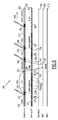
- a time-space chart 200 represents signalling exchange between the protection Optical Line Termination OLT1 at level 202, the currently working Optical Line Termination OLT0 at level 204, the echoing master Optical Network Unit ONU0 at level 206, remaining Optical Network units ONU1, ONU2 at respective level 208, 210 during a nominal operation of the Passive Optical Network 2 in a typical protection process.
- the protection process 200 comprises the preparing step 104 of the take over as described in Figure 3 , the detection of a network failure according to step 106 and a switch over 108 by the protection Optical Line Termination OLT1.
- the network is already set with a master currently working Optical Line Termination 4 as OLT0 and a protection Optical Line Termination 6 as OLT1.
- the protection Optical Line Termination OLT1 is sleeping in a sleeping interval 220.
- the master currently working Optical Line Termination OLT0 sends during a master operation interval 222, a long ECHO message through the signalling messages 224, 226 using the echoing master Optical Network Unit ONU0 as a communication relay.
- the protection Optical Line Termination OLT1 at level 202 Upon reception of the long ECHO message in an ECHO reception time interval 227, the protection Optical Line Termination OLT1 at level 202 triggers the time counting of the ranging gap delay and is set in the sleeping mode during a sleeping interval 228.
- the master currently working Optical Line Termination OLT0 exchanges traffic and signalling data messages 230 with some Optical Network units, here between OLT0 and the Optical Network Units ONU0 and ONU1.
- a conventional step of ranging the Optical Network Unit ONU1 is executed by sending a SCAN message 234 from OLT1 to the selected Optical Network Unit ONU1, by sending a response to the SCAN message from the selected ONU1 to OLT1.
- the master optical Line Termination OLT0 and the remaining Optical Network units ONU0, ONU2 are kept silent in a sleeping window 240 configured so that no collision occurs in uplink between and downlink during the ranging gap 232.
- the master working Optical Line Termination OLT0 avoided sending emitting authorization messages to ONU0 and ONU2 at times configured so that ONU0 and ONU2 are kept silent during the sleeping window 240.
- the master working Optical Line Termination OLT0 sent an ECHO message 244 to the protection Optical Line Termination through the echoing master Optical Network Unit ONU0.
- the ECHO message 244 is sent by the echoing master Optical Network Unit ONU0 at a time defined so that the ECHO message is received by the protection Optical Line Termination OLT1 after the ranging gap. 232 in an ECHO reception time interval 246.
- the ECHO message 244 contains here the date of a next ECHO reception time interval 248 but it may also contain the date of a next ranging gap.
- the ECHO reception time interval 246 is followed by a sleeping time interval 250 during which the master working Optical Line Termination OLT0 is under normal operation in a time interval 252.
- the master working Optical Line Termination OLT0 has sent a short ECHO message 254 relayed by the hop 256 at a time configured so that the ECHO message 254 is received in the ECHO reception time interval 248, the Optical Line Termination OLT1 being awaken at this time.
- the ECHO message 254 relayed by the hop 256 received in the reception time interval 248 contains the date of the next wake up of OLT1 namely the date of a next ECHO reception interval 258. After receiving the date of the next wakeup the protection Optical Line Termination has been set in sleeping mode in the sleeping interval 257.
- the failure prevents new ECHO messages but also data traffic to be received by the protection Optical Line Termination OLT1.
- the protection Optical Line Termination OLT1 When the protection Optical Line Termination OLT1 is woken up it detects a failure and since it is already prepared to switch over, within a very short delay, the protection Optical Line Termination OLT1 becomes the new master Optical Line Termination and takes over the access control of the network for a period of time 262.
- ECHO messages are transmitted through a communication link different from a link using the optical fibres of the Passive Optical Network 2.
- the method according to the invention enables a quick take over of the PON access control by the protection OLT.
- the protection Optical Line Termination is able to detect quickly a failure of the currently working Optical Line Termination.
- the working Optical Line Termination can detect a failure of a protection Optical Line Termination if a corresponding ranging step is not executed.
- the proposed protection scheme avoids that the protection Optical Line Termination impacts significantly the traffic throughput of the network.
Landscapes
- Engineering & Computer Science (AREA)
- Computer Networks & Wireless Communication (AREA)
- Signal Processing (AREA)
- Small-Scale Networks (AREA)
- Optical Communication System (AREA)
Priority Applications (2)
| Application Number | Priority Date | Filing Date | Title |
|---|---|---|---|
| EP09305396A EP2249499A1 (fr) | 2009-05-04 | 2009-05-04 | Procédé de protection d'un réseau optique passif de type B et de préparation d'un transfert de contrôle d'accès par une terminaison de ligne optique de protection à large bande |
| JP2010097660A JP5595783B2 (ja) | 2009-05-04 | 2010-04-21 | 予備系光加入者線端局装置(olt)による、タイプbの保護されているパッシブ光ネットワーク(pon)のアクセス制御のテイクオーバを準備するための方法、タイプbのパッシブ光ネットワーク(pon)を保護するための方法、及び保護されているタイプbのパッシブ光ネットワーク(pon) |
Applications Claiming Priority (1)
| Application Number | Priority Date | Filing Date | Title |
|---|---|---|---|
| EP09305396A EP2249499A1 (fr) | 2009-05-04 | 2009-05-04 | Procédé de protection d'un réseau optique passif de type B et de préparation d'un transfert de contrôle d'accès par une terminaison de ligne optique de protection à large bande |
Publications (1)
| Publication Number | Publication Date |
|---|---|
| EP2249499A1 true EP2249499A1 (fr) | 2010-11-10 |
Family
ID=41066387
Family Applications (1)
| Application Number | Title | Priority Date | Filing Date |
|---|---|---|---|
| EP09305396A Withdrawn EP2249499A1 (fr) | 2009-05-04 | 2009-05-04 | Procédé de protection d'un réseau optique passif de type B et de préparation d'un transfert de contrôle d'accès par une terminaison de ligne optique de protection à large bande |
Country Status (2)
| Country | Link |
|---|---|
| EP (1) | EP2249499A1 (fr) |
| JP (1) | JP5595783B2 (fr) |
Cited By (7)
| Publication number | Priority date | Publication date | Assignee | Title |
|---|---|---|---|---|
| EP2541808A1 (fr) * | 2011-06-27 | 2013-01-02 | ADVA Optical Networking SE | Nýud distant, architecture de réseau et procédé de transmission de données pour réseau de fibres optiques, en particulier pour transmission de données à faible taux de bits |
| CN103166697A (zh) * | 2011-12-09 | 2013-06-19 | 中兴通讯股份有限公司 | 在受保护的无源光网络中的无关于均衡延迟的保护切换 |
| WO2014189953A1 (fr) * | 2013-05-20 | 2014-11-27 | Huawei Technologies Co., Ltd. | Transmissions multipoint coordonnées (comp) dans un réseau optique passif (pon) |
| US8971699B2 (en) | 2012-12-07 | 2015-03-03 | Industrial Technology Research Institute | Optical network failure recovery method |
| CN114095810A (zh) * | 2022-01-21 | 2022-02-25 | 武汉一网万联科技有限公司 | 一种可预防中断的光纤到桌面系统及其布置方法 |
| WO2025082079A1 (fr) * | 2023-10-18 | 2025-04-24 | 华为技术有限公司 | Procédé de gestion d'élément de réseau, terminal de ligne optique et réseau de communication |
| WO2026000964A1 (fr) * | 2024-06-25 | 2026-01-02 | 中兴通讯股份有限公司 | Procédé de traitement de signal pour réseau optique passif, et terminal de ligne optique et unité de réseau optique |
Families Citing this family (1)
| Publication number | Priority date | Publication date | Assignee | Title |
|---|---|---|---|---|
| JP5588548B1 (ja) * | 2013-07-16 | 2014-09-10 | 日本電信電話株式会社 | 光アクセスネットワークシステム及び伝送経路切替方法 |
Citations (1)
| Publication number | Priority date | Publication date | Assignee | Title |
|---|---|---|---|---|
| US20020071149A1 (en) * | 2000-12-12 | 2002-06-13 | Xu Dexiang John | Apparatus and method for protection of an asynchronous transfer mode passive optical network interface |
-
2009
- 2009-05-04 EP EP09305396A patent/EP2249499A1/fr not_active Withdrawn
-
2010
- 2010-04-21 JP JP2010097660A patent/JP5595783B2/ja not_active Expired - Fee Related
Patent Citations (1)
| Publication number | Priority date | Publication date | Assignee | Title |
|---|---|---|---|---|
| US20020071149A1 (en) * | 2000-12-12 | 2002-06-13 | Xu Dexiang John | Apparatus and method for protection of an asynchronous transfer mode passive optical network interface |
Non-Patent Citations (2)
| Title |
|---|
| GROOTE DE J L ET AL: "REDUNDANCY AND PROTECTION-SWITCHING IN APON SYSTEMS", PROCEEDINGS OF THE EUROPEAN CONFERENCE ON NETWORKS AND OPTICAL COMMUNICATIONS 1999. NOC'99. BROADBAND ACCESS AND TECHNOLOGY, AMSTERDAM : IOS PRESS, NL, 1 January 1999 (1999-01-01), pages 119 - 126, XP000829374, ISBN: 978-90-5199-496-4 * |
| XU D J ET AL: "Proposal of a new protection mechanism for ATM PON interface", ICC 2001. 2001 IEEE INTERNATIONAL CONFERENCE ON COMMUNICATIONS. CONFERENCE RECORD. HELSINKY, FINLAND, JUNE 11 - 14, 2001; [IEEE INTERNATIONAL CONFERENCE ON COMMUNICATIONS], NEW YORK, NY : IEEE, US, vol. 7, 11 June 2001 (2001-06-11), pages 2160 - 2165, XP010553700, ISBN: 978-0-7803-7097-5 * |
Cited By (10)
| Publication number | Priority date | Publication date | Assignee | Title |
|---|---|---|---|---|
| EP2541808A1 (fr) * | 2011-06-27 | 2013-01-02 | ADVA Optical Networking SE | Nýud distant, architecture de réseau et procédé de transmission de données pour réseau de fibres optiques, en particulier pour transmission de données à faible taux de bits |
| US8897642B2 (en) | 2011-06-27 | 2014-11-25 | Adva Ag Optical Networking | Remote node and network architecture and data transmission method for a fiber-optic network, especially for low bit-rate data transmission |
| CN103166697A (zh) * | 2011-12-09 | 2013-06-19 | 中兴通讯股份有限公司 | 在受保护的无源光网络中的无关于均衡延迟的保护切换 |
| US9025949B2 (en) | 2011-12-09 | 2015-05-05 | Zte Corporation | Equalization delay agnostic protection switching in protected passive optical networks |
| US8971699B2 (en) | 2012-12-07 | 2015-03-03 | Industrial Technology Research Institute | Optical network failure recovery method |
| WO2014189953A1 (fr) * | 2013-05-20 | 2014-11-27 | Huawei Technologies Co., Ltd. | Transmissions multipoint coordonnées (comp) dans un réseau optique passif (pon) |
| US9590724B2 (en) | 2013-05-20 | 2017-03-07 | Futurewei Technologies, Inc. | Cooperative multi-point (CoMP) in a passive optical network (PON) |
| CN114095810A (zh) * | 2022-01-21 | 2022-02-25 | 武汉一网万联科技有限公司 | 一种可预防中断的光纤到桌面系统及其布置方法 |
| WO2025082079A1 (fr) * | 2023-10-18 | 2025-04-24 | 华为技术有限公司 | Procédé de gestion d'élément de réseau, terminal de ligne optique et réseau de communication |
| WO2026000964A1 (fr) * | 2024-06-25 | 2026-01-02 | 中兴通讯股份有限公司 | Procédé de traitement de signal pour réseau optique passif, et terminal de ligne optique et unité de réseau optique |
Also Published As
| Publication number | Publication date |
|---|---|
| JP2010263620A (ja) | 2010-11-18 |
| JP5595783B2 (ja) | 2014-09-24 |
Similar Documents
| Publication | Publication Date | Title |
|---|---|---|
| EP2249499A1 (fr) | Procédé de protection d'un réseau optique passif de type B et de préparation d'un transfert de contrôle d'accès par une terminaison de ligne optique de protection à large bande | |
| EP2840742B1 (fr) | Système de communication, appareil de station maître, appareil de station esclave, appareil de commande et procédé de commande de communications | |
| JP5106683B2 (ja) | 通信方法、光通信システム、利用者側光回線終端装置、局側光回線終端装置および制御装置 | |
| JP5097641B2 (ja) | 受動光網システム、光多重終端装置及び光網終端装置 | |
| JP5470567B2 (ja) | パッシブ光ネットワーク(pon)の幾つかのサブネットワークによって共有されるアップリンクtdmaアクセスを調整する方法 | |
| CN101677415B (zh) | 光网络系统数据链路切换方法、光网络单元及系统 | |
| KR101403911B1 (ko) | 수동 광 가입자 망 시스템에 이용되는 동적 대역폭 할당 장치 및 그 구현 방법 | |
| US9130676B2 (en) | Transparent protection switching operation in a PON | |
| US20110268435A1 (en) | Communication system, subscriber accommodating apparatus and communication method | |
| CN101873175A (zh) | 光无源网络系统及其运用方法 | |
| US8798460B2 (en) | Optical access system, optical network unit, and optical line terminal | |
| CN108370271A (zh) | 光网络单元的检测方法、装置和无源光网络系统 | |
| TWI474682B (zh) | 用於無線存取系統的方法及網路裝置 | |
| CN101754054B (zh) | 业务传输处理方法、装置和系统 | |
| US7496295B2 (en) | Optical-inclusive dWDM local area network | |
| WO2014181174A1 (fr) | Procédé et appareil permettant de reconfigurer la longueur d'onde d'une unité de réseau optique (onu) | |
| JP2011217298A (ja) | Ponシステムとその局側装置及び宅側装置、rttの補正方法 | |
| CN103139669A (zh) | 数据发送方法及系统 | |
| US8886041B2 (en) | Optical line terminal, bandwidth control method and optical network system | |
| EP3267632A1 (fr) | Dispositif côté station et procédé de surveillance de changement de longueur d'onde | |
| TWI487305B (zh) | 網路裝置及由網路裝置執行的方法 | |
| Fouli et al. | Optical coding for enhanced real-time dynamic bandwidth allocation in passive optical networks | |
| JP2009171434A (ja) | Asonシステムとこれに使用する光スイッチ装置及び局側装置 | |
| Mastrodonato et al. | Analysis of a bandwidth allocation protocol for Ethernet passive optical networks (EPONs) | |
| JP2012257341A (ja) | 通信方法、光通信システム、利用者側光回線終端装置、局側光回線終端装置および制御装置 |
Legal Events
| Date | Code | Title | Description |
|---|---|---|---|
| PUAI | Public reference made under article 153(3) epc to a published international application that has entered the european phase |
Free format text: ORIGINAL CODE: 0009012 |
|
| AK | Designated contracting states |
Kind code of ref document: A1 Designated state(s): AT BE BG CH CY CZ DE DK EE ES FI FR GB GR HR HU IE IS IT LI LT LU LV MC MK MT NL NO PL PT RO SE SI SK TR |
|
| 17P | Request for examination filed |
Effective date: 20110411 |
|
| 17Q | First examination report despatched |
Effective date: 20110516 |
|
| RIC1 | Information provided on ipc code assigned before grant |
Ipc: H04J 14/02 20060101ALI20160318BHEP Ipc: H04Q 11/00 20060101AFI20160318BHEP Ipc: H04J 3/06 20060101ALI20160318BHEP |
|
| GRAP | Despatch of communication of intention to grant a patent |
Free format text: ORIGINAL CODE: EPIDOSNIGR1 |
|
| INTG | Intention to grant announced |
Effective date: 20160601 |
|
| STAA | Information on the status of an ep patent application or granted ep patent |
Free format text: STATUS: THE APPLICATION IS DEEMED TO BE WITHDRAWN |
|
| 18D | Application deemed to be withdrawn |
Effective date: 20161012 |