EP2249721B1 - Tige de liaison de fixation externe à ajustement rapide - Google Patents
Tige de liaison de fixation externe à ajustement rapide Download PDFInfo
- Publication number
- EP2249721B1 EP2249721B1 EP09710983.9A EP09710983A EP2249721B1 EP 2249721 B1 EP2249721 B1 EP 2249721B1 EP 09710983 A EP09710983 A EP 09710983A EP 2249721 B1 EP2249721 B1 EP 2249721B1
- Authority
- EP
- European Patent Office
- Prior art keywords
- joint
- connecting rod
- threaded
- aperture
- rotating member
- Prior art date
- Legal status (The legal status is an assumption and is not a legal conclusion. Google has not performed a legal analysis and makes no representation as to the accuracy of the status listed.)
- Active
Links
Images






Classifications
-
- A—HUMAN NECESSITIES
- A61—MEDICAL OR VETERINARY SCIENCE; HYGIENE
- A61B—DIAGNOSIS; SURGERY; IDENTIFICATION
- A61B17/00—Surgical instruments, devices or methods
- A61B17/56—Surgical instruments or methods for treatment of bones or joints; Devices specially adapted therefor
- A61B17/58—Surgical instruments or methods for treatment of bones or joints; Devices specially adapted therefor for osteosynthesis, e.g. bone plates, screws or setting implements
- A61B17/60—Surgical instruments or methods for treatment of bones or joints; Devices specially adapted therefor for osteosynthesis, e.g. bone plates, screws or setting implements for external osteosynthesis, e.g. distractors, contractors
- A61B17/62—Ring frames, i.e. devices extending around the bones to be positioned
-
- A—HUMAN NECESSITIES
- A61—MEDICAL OR VETERINARY SCIENCE; HYGIENE
- A61B—DIAGNOSIS; SURGERY; IDENTIFICATION
- A61B17/00—Surgical instruments, devices or methods
- A61B17/56—Surgical instruments or methods for treatment of bones or joints; Devices specially adapted therefor
- A61B17/58—Surgical instruments or methods for treatment of bones or joints; Devices specially adapted therefor for osteosynthesis, e.g. bone plates, screws or setting implements
- A61B17/60—Surgical instruments or methods for treatment of bones or joints; Devices specially adapted therefor for osteosynthesis, e.g. bone plates, screws or setting implements for external osteosynthesis, e.g. distractors, contractors
- A61B17/64—Devices extending alongside the bones to be positioned
- A61B17/6466—Devices extending alongside the bones to be positioned with pin-clamps movable along a solid connecting rod
- A61B17/6475—Devices extending alongside the bones to be positioned with pin-clamps movable along a solid connecting rod the connecting rod being threaded
-
- A—HUMAN NECESSITIES
- A61—MEDICAL OR VETERINARY SCIENCE; HYGIENE
- A61B—DIAGNOSIS; SURGERY; IDENTIFICATION
- A61B17/00—Surgical instruments, devices or methods
- A61B2017/00982—General structural features
- A61B2017/00991—Telescopic means
-
- A—HUMAN NECESSITIES
- A61—MEDICAL OR VETERINARY SCIENCE; HYGIENE
- A61B—DIAGNOSIS; SURGERY; IDENTIFICATION
- A61B17/00—Surgical instruments, devices or methods
- A61B17/56—Surgical instruments or methods for treatment of bones or joints; Devices specially adapted therefor
- A61B2017/564—Methods for bone or joint treatment
Definitions
- the present disclosure relates in general to the field of external fixation, and more specifically, to connection rods having articulatable joints for attachment to the rings or other external supports of the fixation device.
- external fixation devices are commonly used in a variety of surgical procedures including limb lengthening, deformity correction, fracture reduction and treatment of non-unions, mal-unions and bone defects.
- the process involves a rigid framework comprising several rings that are placed externally around the limb and attached to bone segments using wires and half pins inserted into the bone segments and connected to the related section of the external rigid framework.
- the opposite rings of the rigid framework are interconnected by either threaded or telescopic rods directly or in conjunction with uni-planar or multi-planar hinges, which allow the surgeon to connect opposite rings that are not parallel to each other after manipulation with bone segments either rapidly (acutely) or gradually over a period of time.
- the wires and half pins are inserted into each bone segment and attached to rings of a rigid framework.
- the rigid framework is used to acutely reduce a displacement and restore alignment between the bone segments.
- the orientations of opposite rings often are not parallel.
- Those opposite rings of the rigid framework are connected together by threaded or telescopic rods with attached uni-planar or multi-planar hinges. This allows the opposite bone segment to be rigidly fixed until complete fracture healing or bone consolidation is completed.
- EP 0 029 298 discloses a connecting rod for an external fixation device according to the precharacterizing portion of claim 1.
- the present enclosure includes examples of a external fixation connection rod that allows for rapid, coarse adjustments of the rod length and is operable to be easily and rigidly attached to non-parallel external fixator rings.
- Described in one embodiment is a connecting rod for an external fixation device as defined in claim 1. Further embodiments of the invention are defined in the dependent claims.
- the present disclosure includes examples directed to an external fixation connection rod with a housing that allows for rapid and gradual adjustment in length and having joint attachments to parallel or non-parallel rings or other external supports.
- the external fixation connection rod includes a telescopic housing having an axial bore defined therethrough.
- a first joint is coupled to an end portion of the housing body, and a first rotating member is received in the first joint.
- the first rotating member is operable to rotate relative to the first joint about a first axis, and comprises a first connection mechanism.
- the first connection mechanism releasably couples the first rotating member to a first fixator ring.
- An adjustment sleeve is slidably disposed within the axial bore of the telescopic housing, and a sleeve fastener is used to secure the adjustment sleeve to the telescopic housing.
- the adjustment sleeve allows for coarse longitudinal length adjustments with respect to the telescopic housing.
- the adjustment sleeve comprises an adjustment mechanism having a rotation element.
- the rotation element has an internally threaded bore defined therethrough, which allows for threaded connection to a threaded elongated member.
- the elongated member includes a threaded rod, and the external thread of the threaded rod and the internal thread of the threaded bore mate with each other such that rotating the rotation element causes the threaded elongated member to translate along a longitudinal axis of the connecting rod. Coupled to an end portion of the threaded rod is a second joint and a second rotating member received in the second joint.
- the second rotating member includes a second connection mechanism operable to releasably couple the second rotating member to a second fixator ring. Additionally, the first and second connection mechanism are operable to substantially limit the rotational movement of the first and second rotating members, respectively.
- FIGURE 1 is a perspective view of one external fixation connection rod.
- the external fixation connection rod 10 includes a first articulatable joint 12 that houses a first rotating member 14.
- the first rotating member 14 includes a fastener 16 inserted into a fastener aperture defined (not shown) in the first rotating member 14 to secure the first articulatable joint 12 to an external fixator ring or other fixation device (not shown).
- a telescopic housing 18 extends from the first articulatable joint 12 and has an axial bore (not shown) extending longitudinally from the first articulatable joint 12.
- the first articulatable joint 12 allows angular and rotational alignment of the telescopic housing 18.
- the telescopic housing 18 includes a telescopic housing adjustment aperture 20 in a wall of the telescopic housing.
- An adjustment sleeve 22 is positioned in the axial bore (not shown) of the telescopic housing 18.
- the adjustment sleeve 22 is slidable within the axial bore (not shown) to allow adjustment of the end-to-end length of the connecting rod 10 in a rapid manner.
- the adjustment sleeve 22 includes a sleeve fastener 24 disposed through the telescopic housing adjustment aperture 20 to secure the adjustment sleeve 22 to the telescopic housing 18.
- An adjustment mechanism 26 is positioned at one end of the adjustment sleeve 22 and threadably connected to a threaded elongated member 28.
- the adjustment mechanism 26 adjusts longitudinally the threaded elongated member 28 to adjust the overall end-to-end length of the connecting rod 10 in a gradual manner.
- the threaded elongated member 28 includes a second articulatable joint 30 that includes a second articulatable joint housing 32 adapted to fit a second rotating member 34.
- the second rotating member 34 includes a second fastener 36 that is received in a fastener aperture (not shown) defined in the second rotating member 34 to secure the second articulatable joint 30 to an external fixator ring or other external support (not shown).
- FIGURE 2 is an exploded view of the connecting rod shown in FIGURE 1 .
- the external fixation connection rod 10 includes a first articulatable joint 12 that houses a first rotating member 14.
- the first rotating member 14 passes through a joint aperture 38 that is sized and proportioned to fit the first rotating member 14.
- a fastener 16 passes through a slot (not shown) in the first articulatable joint 12 and into a fastener aperture 40 defined in the first rotating member 34 to secure the first articulatable joint 12 to an external fixator ring or other external support (not shown).
- the first articulatable joint 12 allows angular and rotational alignment of the external fixation connection rod 10 relative to the first external fixator ring or other external support.
- a telescopic housing 18 extends from the first articulatable joint 12 and has an axial bore (not shown) extending longitudinally from the first articulatable joint 12 to the axial bore aperture 42.
- the telescopic housing 18 includes a telescopic housing adjustment aperture 20.
- An adjustment sleeve 22 is slidably disposed within the axial bore (not shown) of the telescopic housing 18.
- the adjustment sleeve 22 is slidable within the axial bore (not shown) to allow adjustment of the end-to-end length of the external fixation connection rod 10 in a rapid manner.
- the adjustment sleeve 22 includes a sleeve fastener 24 that is inserted through a central opening 44 defined in a sleeve fastener washer 46 and through the telescopic housing adjustment aperture 20 into a sleeve fastener aperture 48 defined in the adjustment sleeve 22.
- An adjustment mechanism 26 is rotatably coupled to an end portion of the adjustment sleeve 22 and threadably connected to a threaded elongated member 28.
- the adjustment mechanism is operable to rotate but not translate relative to the end portion of the adjustment sleeve 22.
- the adjustment mechanism 26 adjusts longitudinally the threaded elongated member 28 to adjust the overall end-to-end length of the external fixation connection rod 10 in a gradual manner.
- the threaded elongated member 28 includes a second articulatable joint 30.
- the second articulatable joint 30 includes a second articulatable joint housing 32 adapted to fit a second rotating member 34.
- the second rotating member 34 passes through a second joint aperture 50 that is sized and proportioned to fit the second rotating member 34.
- a second fastener 36 disposed through a slot (not shown) in the second articulatable joint 30 and into a second fastener aperture 52 defined in the second rotating member 34 to secure the second articulatable joint 30 to an external fixator ring or other fixation device (not shown).
- the second articulatable joint 30 allows angular and rotational alignment of the external fixation connection rod 10 relative to the second external fixator ring (not shown) or other external support.
- FIGURE 3 is a cutaway view of the connecting rod shown in FIGURES 1-2 .
- the external fixation connection rod 10 includes a first articulatable joint 12 that houses a first rotating member 14.
- the first rotating member 14 passes through a joint aperture 38 that is sized and proportioned to fit the first rotating member 14.
- a fastener 16 is disposed through a slot 54 in the first articulatable joint 12 and rotating member aperture 40 into a fastener aperture 56 defined in the first rotating member 14 to secure the first articulatable joint 12 to an external fixator ring or other external support (not shown).
- the first articulatable joint 12 allows angular and rotational alignment of the external fixation connection rod 10 relative to the first external fixator ring (not shown) or other external support.
- a telescopic housing 18 extends from the first articulatable joint 12 and has an axial bore 58 extending longitudinally from the first articulatable joint 12 to the axial bore aperture 42.
- the telescopic housing 18 includes a telescopic housing adjustment aperture 20.
- An adjustment sleeve 22 is slidably disposed within the axial bore 58 of the telescopic housing 18. The adjustment sleeve 22 is slidable within the axial bore 58 to allow adjustment of the end-to-end length of the external fixation connection rod 10 in a rapid manner.
- the adjustment sleeve 22 includes a sleeve fastener 24 that is inserted through a sleeve fastener washer aperture 44 centrally defined in the sleeve fastener washer 46 and through the telescopic housing adjustment aperture (not shown) into a sleeve fastener aperture 48.
- the sleeve fastener 24 may include a separate sleeve washer 46 as a single unit.
- An adjustment mechanism 26 is rotatably disposed at an end portion of the adjustment sleeve 22 and threadably connected to a threaded elongated member 28.
- the adjustment mechanism 26 may include a rotation element, the rotation element having an internally threaded bore defined therethrough.
- the threaded elongated member 28 is disposed through the threaded bore 60 of the rotation element of the adjustment mechanism, and the external thread of the elongated member and the internal thread of the threaded bore mate with each other such that rotating the rotation element of the adjustment mechanism 26 causes the threaded elongated member 28to translate along a longitudinal axis of the connecting rod.
- the adjustment mechanism 26 adjusts longitudinally the threaded elongated member 28 to adjust the overall end-to-end length of the external fixation connection rod 10 in a gradual manner.
- the threaded elongated member 28 includes a second articulatable joint 30.
- the second articulatable joint 30 includes a second articulatable joint housing 32 adapted to fit a second rotating member 34.
- the second rotating member 34 passes through a second joint aperture 50 that is sized and proportioned to fit the second rotating member 34.
- a second fastener 36 is inserted through a slot 62 in the second articulatable joint 30 and a second rotating member aperture 52 into a second threaded fastener bore 64 to secure the second articulatable joint 30 to an external fixator ring or other external support (not shown).
- the second articulatable joint 30 allows angular and rotational alignment of the external fixation connection rod 10 relative to the second external fixator ring (not shown) or other external support.
- FIGURE 4 is a perspective view of a portion of the external fixation connection rod of the present disclosure.
- the articulatable joint 30 includes an articulatable joint housing 32 adapted to fit a rotating member 34.
- the rotating member 34 passes through an articulatable joint aperture 50 that is sized and proportioned to fit the rotating member 34.
- a fastener (not shown) is inserted through a slot 62 in the articulatable joint 30 and a rotating member aperture 52 into a threaded fastener bore (not shown) to secure the articulatable joint 30 to an external fixator ring or other external support (not shown).
- the articulatable joint 30 may be textured 76 to provide increased adhesion or traction to the external fixator ring or other external supports (not shown).
- FIGURE 5 is an exploded view of a portion of the external fixation connection rod of the present disclosure.
- the articulatable joint 30 includes an articulatable joint housing 32 adapted to fit a rotating member 34.
- the rotating member 34 passes through a joint aperture 50 that is sized and proportioned to fit the rotating member 34.
- a fastener 36 is inserted through a slot 62 in the articulatable joint 30 and a rotating member aperture 52 into a threaded fastener bore (not shown) to secure the articulatable joint 30 to an external fixator ring or other external support (not shown).
- the articulatable joint 30 may be textured 76 to provide increased adhesion or traction to the external fixator ring or other external supports (not shown).
- FIGURE 6 is a side view of an external fixation connection rod.
- the external fixation connection rod 10 includes a first articulatable joint 12 that houses a first rotating member 14.
- the first rotating member 14 includes a fastener 16 that is inserted through a slot (not shown) in the first articulatable joint 12 to secure the first articulatable joint 12 to an external fixator ring or other external support (not shown).
- the first articulatable joint 12 may be rotated about the X1 axis of the first rotating member 14 and around the Y1 axis of the fastener 16. This movement allows the first articulatable joint 12 to be secured by the fastener 16 at different angles relative to an external fixator ring or other fixation support (not shown).
- a telescopic housing 18 extends from the first articulatable joint 12 and has an axial bore (not shown) extending longitudinally from the first articulatable joint 12.
- the telescopic housing 18 includes a telescopic housing adjustment aperture 20.
- An adjustment sleeve 22 is slidably disposed within the axial bore (not shown) of the telescopic housing 18.
- the adjustment sleeve 22 is slidable within the axial bore (not shown) to allow adjustment of the end-to-end length "A" of the external fixation connection rod 10 in a rapid manner.
- the movement of the adjustment sleeve 22 in the axial bore (not shown) of the telescopic housing 18 allows the distance "B" to be changed and in turn change the end-to-end length "A" of the external fixation connection rod 10.
- the adjustment sleeve 22 includes a sleeve fastener (not shown) disposed through the telescopic housing adjustment aperture 20 to secure the adjustment sleeve 22 to the telescopic housing 18.
- the telescopic housing adjustment aperture 20 also serves as a window to allow positioning and referencing of the adjustment sleeve 22 and or the threaded elongated member 28 to aid in the adjustment of the end-to-end length "A" of the external fixation connection rod 10 in a rapid manner.
- An adjustment mechanism 26 is rotatably disposed at an end portion of the adjustment sleeve 22 and threadably connected to a threaded elongated member 28.
- the adjustment mechanism 26 may be rotated in direction "Z" to engage the threads of the threaded elongated member 28 and thereby adjust longitudinally the distance "C" and directly affect the end-to-end length "A" of the external fixation connection rod 10 in a gradual manner.
- the threaded elongated member 28 includes a second articulatable joint 30 that includes a second articulatable joint housing 32 adapted to fit a second rotating member 34.
- the second rotating member 34 includes a second fastener 36 that is inserted through a slot (not shown) in the second articulatable joint housing 32 to secure the second articulatable joint 30 to an external fixator ring or other external support (not shown).
- the second articulatable joint 30 may be rotated about the X2 axis of the second rotating member 34 and around the Y2 axis of the second fastener 36. This movement allows the second articulatable joint 32 to be secured by the fastener 36 at different angles relative to an external fixator ring or other fixation support (not shown). It is not necessary for the first articulatable joint 12 be at the same angle, position or face relative to the second articulatable joint 30. In addition, the first articulatable joint 12, the second articulatable joint 30 or both articulatable joint 30 may be textured 76 to provide increased adhesion or traction to the external fixator ring or other external supports (not shown).
- the graduation marks 74 may be calibrated into discrete increments (e.g., one millimeter increments) and may indicate the distance between the first articulatable joint 12 and the second articulatable joint 30 and relate to the end-to-end length "A" of the external fixation connection rod 10.
- the graduation marks 74 indicate the lengths of the external fixation connection rod 10 as a relative value, rather than the distance from some predetermined specific length.
- the graduation marks do not necessarily have to be based on a traditional measuring system, or indicate the effective length of the strut at all.
- the graduation marks could indicate the percentage of total rod extension, or daily increments for cases where the translation takes place over an extended period of time.
- Reference to a neutral position can be useful to set the base members at a predetermined "neutral" position.
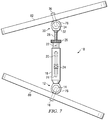
- FIGURE 7 is a side view of an external fixation connection rod attached to an external fixation device.
- An external fixation connection rod 10 is connected between a first external fixator ring 80 and a second external fixator ring 82.
- FIGURE 7 depicts a single external fixation connection rod 10 disposed between the first external fixator ring 80 and the second external fixator ring 82 for simplicity sake.
- numerous connecting rods 10 may be attached at various positions about the external fixator rings, that the angle of the external fixation connection rod 10 relative to the first external fixator ring 80 and the second external fixator ring 82 may be varied and the length of the external fixation connection rod 10 may be varied and adjusted.
- a first articulatable joint 12 is secured to the external fixator ring 80 or other external support.
- the external fixation connection rod 10 includes a first articulatable joint 12 that houses a first rotating member 14.
- the first rotating member 14 includes a fastener 16 that passes through an aperture (not shown) defined in the first external fixator ring 80 and through a slot (not shown) in the first articulatable joint 12 to secure the first articulatable joint 12 to the external fixator ring 80 or other external support.
- the first rotating member 14 may be rotated to position the fastener 16 at different positions and in turn at different locations in the slot (not shown) of the first articulatable joint 12. This movement allows the first articulatable joint 12 to be secured at different angles relative to an external fixator ring 80 or other external support.
- a telescopic housing 18 extends from the first articulatable joint 12 and has an axial bore (not shown) extending longitudinally from the first articulatable joint 12.
- the telescopic housing 18 includes a telescopic housing adjustment aperture 20.
- An adjustment sleeve 22 is slidably disposed within the axial bore (not shown) of the telescopic housing 18.
- the adjustment sleeve 22 is slidable within the bore (not shown) to allow adjustment of the end-to-end length "A" of the connecting rod 10 in a rapid manner.
- the adjustment sleeve 22 includes a sleeve fastener 24 positioned through the telescopic housing adjustment aperture 20 to secure the adjustment sleeve 22 to the telescopic housing 18.
- the telescopic housing adjustment aperture 20 also serves as a window to allow positioning and referencing of the adjustment sleeve 22 and or the threaded elongated member 28 to aid in the adjustment of the end-to-end length of the external fixation connection rod 10.
- the graduation marks 74 indicate the lengths of the external fixation connection rod 10 as a relative value, rather than the distance from some predetermined specific length.
- the graduation marks do not necessarily have to be based on a traditional measuring system, or indicate the effective length of the strut at all. For instance, the graduation marks could indicate the percentage of total rod extension, or daily increments for cases where the translation takes place over an extended period of time. Reference to a neutral position can be useful to set the base members at a predetermined "neutral" position.
- An adjustment mechanism 26 is rotatably disposed at an end portion of the adjustment sleeve 22 and threadably connected to a threaded elongated member 28.
- the adjustment mechanism 26 may be rotated to engage the threads of the threaded elongated member 28 and thereby adjust longitudinally the end-to-end length of the connecting rod 10 in a gradual manner.
- the threaded elongated member 28 includes a second articulatable joint 30 with a second articulatable joint housing 32 adapted to fit a second rotating member 34.
- the second rotating member 34 includes a second fastener 36 that is inserted through an aperture (not shown) defined in the second external fixator ring 82 and into a slot (not shown) in the second articulatable joint housing 32 to secure the second articulatable joint 30 to an external fixator ring 82 or other external support.
- the second articulatable joint 30 may be rotated to position the second fastener 36 at different positions and in turn at different locations in the slot of the second articulatable joint 30. This movement allows the second articulatable joint 30 to be secured at different angles relative to an external fixator ring 82 or other external support. It is not necessary for the first articulatable joint 12 be at the same angle, position or face relative to the second articulatable joint 30. In addition, the first articulatable joint 12, the second articulatable joint 30 or both articulatable joints 30 may be textured 76 to provide increased adhesion or traction to the external fixator ring 80 and 82 or other external supports.
- FIGURE 8 is a perspective view of an external fixation device using the external fixation connection rod of the present disclosure.
- the external fixation device includes a first external fixator ring 80 and a second external fixator ring 82 connected by one or more external fixation connection rods 10.
- Each of the external fixation connection rods (10a, 10b, and 10c) includes a first articulatable joint that houses a first rotating member.
- the first rotating member includes a fastener inserted through a slot (not shown) in the first articulatable joint to secure the first articulatable joint to an external fixator ring 80.
- the external fixation connection rod 10 may be any connection rods described in this disclosure or constructed in accordance to the principles disclosed herein.
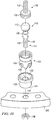
- an external fixation connection rod 10 includes a telescopic housing 100 having an axial bore (not shown) defined therethrough.
- a first joint 102 is coupled to an end portion 104 of the housing body 106, and a first rotating member 103 is received in the first joint 102.
- the first joint 102 includes a socket 108 that may be integrally connected or releasably coupled to the end portion 104 of the housing body 106.
- the first rotating member 103 includes a ball member 110, which is operable to rotate relative to the socket 108 about a first axis.
- the external fixation connection rod 10 further includes a seating member 120 having an inner recessed portion 122 for receiving the socket 108 of first joint 102.
- the seating member 120 further has an outer ring contact portion 124 for providing a contact surface with a first fixator ring 200.
- the outer ring contact portion 124 may include grooves 128 defined therein to improve traction with the ring.
- the illustrated embodiment includes seating members 120 to improve the traction with the fixator ring 200, it is to be appreciated that some embodiments may not include a seating member 120.
- the first rotating member 103 also includes a first connection mechanism 112 operable to releasably couple the first rotating member 103 to the first fixator ring 200.
- the first connection mechanism 112 includes a first connecting body 130 extending radially from the ball member 110 to the outside of the socket 108 of the first joint 102, and through an aperture defined in the seating member 102.
- the first connecting body 130 has a threaded portion 132 operable to be inserted through a bore 134 defined in the first ring 200.
- a nut 136 is disposed over the threaded portion 132, which can be tightened to cause the ball member 110 to exert a pulling force on the socket 108 and seating member 102.
- the first connecting body 130 further comprises a flared portion 138
- the aperture 126 defined in the seating member 120 comprises a corresponding interfering portion operable to cooperate with the flared portion 138 of the first connecting body 130 to limit the rotational movement of the ball member 110 relative to the socket 108.
- the socket 108 and ball member 110 may be configured to satisfy various design needs.
- the socket 108 in some embodiments may include a plurality of recessed portions defined in the wall of the socket 108 as illustrated in FIGURES 9-12 .
- the recessed portions in the wall of socket 108 allow the ball member 110 and joint 102 to automatically, and without excessive rotation, accommodate the various orientations of the rings 200 as the ball member 110 and socket 108 are being locked to the first ring 200.
- the recessed portions are aligned such that they cooperate to form crossed channels.
- an adjustment sleeve 140 slidably disposed within the axial bore (not shown) of the telescopic housing 100, and a sleeve fastener 142 is used to secure the adjustment sleeve 140 to the telescopic housing 100.
- the adjustment sleeve 140 allows for coarse longitudinal length adjustments with respect to the telescopic housing 100.
- the adjustment sleeve comprises an adjustment mechanism 144 having a rotation element 146, such as a thumb wheel.
- the rotation element 146 has an internally threaded bore (not shown) defined therethrough, which allows for threaded connection to a threaded elongated member 148.
- the elongated member includes a threaded rod 150 and the external thread of the threaded rod and the internal thread of the threaded bore mate with each other such that rotating the rotation element 146 causes the threaded elongated member 148 to translate along a longitudinal axis of the connecting rod 10.
- Coupled to an end portion 152 of the threaded rod 150 is a second joint 102 and a second rotating member 103 received in the second joint 102.
- the second rotating member 103 includes a second connection mechanism 112 operable to releasably couple the second rotating member 103 to a second fixator ring 200.
- the configurations of the second joint 102, second rotating member 103, and the second connection mechanism 112 are similar to the configurations of the first joint 102, first rotating member 103, and the first connection mechanism 112 as described above.
- a seating member 120 can be disposed between the rotating member 103 and the second fixator ring 200 to improve traction as discussed above.
- the external fixation connection rod 10 configured to accommodate an external fixation device with a relatively short ring-to-ring length.
- the external fixation connection rod 10 includes a telescopic housing 300 having a housing body, in which a first portion of the housing body 300 comprises a first axial bore defined therethrough, and a second portion of the housing body 300 comprises a second axial bore defined therethrough.
- the first and second axial bores define first and second longitudinal axes, respectively, and the first and second longitudinal axes are parallel and coplanar.
- the housing body further comprises first and second apertures 310 defined in the walls of the first and second portions of the housing body 300, respectively.
- the first and second apertures 300 are aligned along the first and second axes, respectively.
- Sleeves 302 and 304 are slidably disposed in the first and second axial bores, respectively, and each include a fastener aperture (not shown) defined therein.
- Fastener 306 are inserted through the housing apertures 310 and received in the fastener apertures of the first and second sleeves 302 and 304 to lock the sleeves in a desired longitudinal position. As such, the longitudinal movement of the sleeves 302 and 304 in the axial bores allows for coarse length adjustments.
- the sleeve 304 further includes an adjustment mechanism 314 having a rotation element 316.
- the rotation element 316 is rotatably disposed on an end portion of the sleeve 304, and has an internally threaded bore defined therethrough.
- a threaded elongated member 318 is disposed through the threaded bore of the rotation element 316 of the adjustment mechanism 314. The external thread of the elongated member and the internal thread of the threaded bore engage each other such that rotating the rotation element 316 causes the threaded elongated member 318 to translate along a longitudinal axis of the connecting rod.
- a joint 320 is disposed on an end portion of the threaded elongated member 318 for connection with an external ring or support device.
- the joint 312 may be any suitable joints or connectors described in the present application or known in the art.
- the sleeve 302 also includes a joint 312 at an end portion for connection with an external ring or support device.
- the joint 312 may be any suitable joints or connectors described in the present application or known in the art.
- the sleeve 302 can also include a second adjustment mechanism rotatably disposed on an end portion of the second sleeve.
- the second adjustment mechanism is threadably coupled to a second elongated member, and rotating the second adjustment mechanism causes the second elongated member to translate along the second axis of the second axial bore.
- the present disclosure also describes examples for maintaining the orientation of first and second fixator rings for immobilizing bone segments.
- a connecting rod comprising a telescopic housing having an axial bore defined therethrough; an adjustment sleeve slidably disposed within the axial bore, the adjustment sleeve and the telescopic housing; and an externally threaded elongated member threadably coupled the adjustment sleeve.
- a first joint is coupled to an end portion of the housing, and a first rotating member is received in the first joint.
- the first rotating member comprises a first connection mechanism operable to releasably couple the first rotating member to the first fixator ring and substantially limit the rotational movement of the first rotating member.
- a second joint is coupled to an end portion of the housing, and a second rotating member is received in the second joint.
- the second rotating member comprises a second connection mechanism operable to releasably couple the second rotating member to the second fixator ring and substantially limit the rotational movement of the second rotating member.
- the disclosed example further includes adjusting the longitudinal position of adjustment sleeve relative to the telescopic housing, and releasably coupling the adjustment sleeve to the telescopic housing using a sleeve fastener.
- the disclosed example further includes using the first connection mechanism to releasably couple the first rotating member to the first fixator ring and substantially limit the rotational movement of the first rotating member, and using the second connection mechanism to releasably couple the second rotating member to the second fixator ring and substantially limit the rotational movement of the second rotating member.
- Methods using a connecting rod may be performed with a subject, e.g., a human or another vertebrate animal.
- One or more bones (of the subject) to be fixed may be selected. Any suitable bone(s) may be selected, such as a long bone(s) and/or at least a pair of bones connected via an anatomical joint.
- Exemplary bones include leg bones (femur, tibia, and fibula), arm bones (humerus, radius, and ulna), foot bones (calcaneus, talus, metatarsals, and phalanges), wrist/hand bones (carpals, metacarpals, and phalanges), etc.
- one or more bones including at least one long bone may be selected.
- An external fixation device may be constructed along and at least partially around the selected bone(s).
- the external fixation device may include a plurality of rings fixed in position relative to one another by numerous connecting rods secured to the rings.
- the external fixation device may be connected to the selected bone(s). Connection may be performed at any suitable time, such as before, during, and/or after construction of the external fixation device.
- the external fixation device may be assembled and then connected to bone, or individual external fixation device members or external fixation device sub-assemblies may be connected to the bone before the external fixation device is fully assembled.
- Connection of the external fixation device to bone may include placing connectors, such as wires, pins, screw, and/or rods, among others, through the skin and into, through, and/or around the selected bone.
- the external fixation device may be reconfigured while it is connected to the one or more selected bones.
- Reconfiguration may include adjusting the length, angle, position, and/or connection site of one or more external fixation device components, particularly connecting rod.
- Reconfiguration may involve lengthening and/or shortening one or more (or all) connecting rods of the external fixation device.
- Reconfiguration may involve replacing one or more connecting rods with a different connecting rod(s).
- the different connecting rod may be of different size, pivotability, adjustability, shape, and/or the like.
- the external fixation device may be braced to facilitate reconfiguration. Bracing the external fixation device may stiffen and/or stabilize the external fixation device such that reconfiguration produces fewer undesired changes to the external fixation device structure as the external fixation device is weakened and altered during reconfiguration. Bracing may be performed by a pair of connecting rods of the external fixation device.
- the brace may be configured to be clipped onto the external fixation device members before the brace is fully secured to the external fixation device members.
- the brace may include one or more external fixation device engagement elements that are biased to opposingly engage one or more respective external fixation device members.
- each engagement element may be secured in place on the external fixation device member by operating a user control, manually or with a tool.
- the relative spacing and angular disposition of the engagement elements may be fixed by operating a user control, either the same user control(s) for securing the engagement element to a frame member or a distinct user control.
- the brace may include one or more movable joints, and the brace may be installed in engagement with the external fixation device members with one or more of the joints in a movable configuration. The movable joints then may be adjusted to a locked (fixed) configuration.
- the brace may include a plurality of movable joints and one or more of the movable joints may be locked before or during brace placement onto the frame, and one or more other of the movable joints may be locked after brace placement onto the external fixation device.
- the brace may be removed after frame reconfiguration. Accordingly, the brace may be installed with the frame (and connecting rod) fixing bone and removed with the frame reconfigured and still fixing bone.
- the brace thus may be present on the external fixation device for only a fraction of the time that the external fixation device is fixing bone.
- the words “comprising” (and any form of comprising, such as “comprise” and “comprises”), “having” (and any form of having, such as “have” and “has”), "including” (and any form of including, such as “includes” and “include”) or “containing” (and any form of containing, such as “contains” and “contain”) are inclusive or open-ended and do not exclude additional, unrecited elements or method steps.
- A, B, C, or combinations thereof refers to all permutations and combinations of the listed items preceding the term.
- A, B, C, or combinations thereof is intended to include at least one of: A, B, C, AB, AC, BC, or ABC, and if order is important in a particular context, also BA, CA, CB, CBA, BCA, ACB, BAC, or CAB.
- expressly included are combinations that contain repeats of one or more item or term, such as BB, AAA, MB, BBC, AAABCCCC, CBBAAA, CABABB, and so forth.
- the skilled artisan will understand that typically there is no limit on the number of items or terms in any combination, unless otherwise apparent from the context.
Landscapes
- Health & Medical Sciences (AREA)
- Orthopedic Medicine & Surgery (AREA)
- Life Sciences & Earth Sciences (AREA)
- Surgery (AREA)
- Biomedical Technology (AREA)
- Engineering & Computer Science (AREA)
- Nuclear Medicine, Radiotherapy & Molecular Imaging (AREA)
- Heart & Thoracic Surgery (AREA)
- Medical Informatics (AREA)
- Molecular Biology (AREA)
- Animal Behavior & Ethology (AREA)
- General Health & Medical Sciences (AREA)
- Public Health (AREA)
- Veterinary Medicine (AREA)
- Surgical Instruments (AREA)
Claims (12)
- Une tige de connexion (10) pour un dispositif de fixation externe, la tige de connexion (10) définissant un axe longitudinal et comprenant :un boitier télescopique (100) comprenant :un corps de boitier (106) présentant un trou axial défini à travers celui-ci,un premier joint (102) couplé à une extrémité (104) du corps de boitier (106) ;un premier organe rotatif (103) reçu dans le premier joint (102), dans lequelle premier organe rotatif (103) est adapté pour tourner par rapport au premier joint (102) autour d'un premier axe orthogonal à l'axe longitudinal de la tige de connexion (10), et le premier organe rotatif (103) comprend un premier mécanisme de connexion (112) adapté pour coupler de manière débrayable le premier organe rotatif (103) à une première bague de fixation (200) ;un manchon d'ajustement (140) disposé de manière coulissante dans le trou axial, le manchon d'ajustement (140) et le boitier télescopique (100) étant couplés de manière débrayable par un moyen d'attache (142) ; etun organe allongé à filetage externe (148) couplé par vissage au manchon d'ajustement (140), l'organe allongé (148) comprenant :une tige filetée (150),
un deuxième joint (102) couplé à une extrémité (152) de la tige filetée (150) ;un deuxième organe rotatif (103) reçu dans le deuxième joint (102), dans lequel le deuxième organe rotatif (103) est adapté pour tourner par rapport au deuxième joint (102) autour d'un deuxième axe orthogonal à l'axe longitudinal de la tige de connexion, et le deuxième organe rotatif (103) comprend un deuxième mécanisme de connexion (112) adapté pour coupler de manière débrayable le deuxième organe rotatif (103) à une deuxième bague de fixation (200),caractérisé en ce que les premier et deuxième joints (102) comprennent chacun une cavité de rotule (108), l'organe rotatif (103) respectif comprend un organe de tête de rotule (110), et l'organe de tête de rotule (110) est disposé dans la cavité de rotule (108), la cavité de rotule (108) comprend une pluralité de parties renfoncées définies dans une paroi de chaque cavité de rotule (108) permettant un accroissement d'une plage de mouvement de l'organe de tête de rotule (110) dans la cavité de rotule. - La tige de connexion de la revendication 1, dans laquelle les parties renfoncées définies dans la cavité de rotule (108) du premier joint (102) coopèrent pour former des canaux croisés.
- La tige de connexion de la revendication 1, dans laquelle les premier et second mécanismes de connexion (112) comprennent chacun une ouverture de moyen d'attache, définie dans le premier et le deuxième organe rotatif (103) respectivement, et en outre dans laquelle chaque ouverture de moyen d'attache est adaptée pour recevoir un moyen d'attache de bague disposé à travers un trou défini dans la première ou la deuxième bague (200).
- La tige de connexion de la revendication 2, dans laquelle le premier joint (102) comprend une surface texturée (124) adaptée pour fournir un contact avec frottement avec une surface de la première bague (200), et optionnellement ou préférablement dans laquelle la surface texturée (124) comprend des rainures parallèles (128) qui y sont définies.
- La tige de connexion de la revendication 2, dans laquelle le deuxième joint (128) comprend une surface texturée (124) adaptée pour fournir un contact avec frottement avec une surface de la première bague (200), et optionnellement ou préférablement dans laquelle la surface texturée (124) comprend des rainures parallèles (128) qui y sont définies.
- La tige de connexion de la revendication 1, dans laquelle les cavités de rotule (108) des premier et deuxième joints (102) sont respectivement assises dans un premier et un deuxième organes d'assise (120), les organes d'assise (120) ayant chacun une partie interne renfoncée (122) pour recevoir la cavité de rotule (108) du premier ou du deuxième joint (102), et ayant en outre une partie de contact de bague extérieure (124) pour fournir une surface de contact avec la première ou la deuxième bague (200).
- La tige de connexion de la revendication 5, dans laquelle le premier mécanisme de connexion (112) comprend un premier corps de connexion (130) s'étendant radialement du premier organe de tête de rotule (110), jusqu'à l'extérieur de la cavité de rotule (108) du premier joint (102), et à travers une ouverture (126) définie dans le premier organe d'assise (120), et en outre dans laquelle le premier corps de connexion (130) a une partie filetée (132) adaptée pour être insérée à travers un trou (134) défini dans la première bague (200); dans laquelle le deuxième mécanisme de connexion (112) comprend un deuxième corps de connexion (130) s'étendant radialement du deuxième organe de tête de rotule (110), jusqu'à l'extérieur de la cavité de rotule (1089 du deuxième joint (102), et à travers une ouverture (126) définie dans le deuxième organe d'assise (120), et en outre dans laquelle le deuxième corps de connexion (130) a une partie filetée (132) adaptée pour être insérée à travers un trou (134) défini dans la deuxième bague (200); et dans laquelle les parties filetées (132) des premier et deuxième corps de connexion (130) sont chacun adapté pour recevoir un écrou d'accouplement (136).
- La tige de connexion de la revendication 6, dans laquelle le premier corps de connexion (130) comprend une partie évasée (138), et l'ouverture (126) définie dans le premier organe d'assise (120) comprend une partie interférente correspondante adaptée pour coopérer avec la partie évasée (138) du premier corps de connexion (130) pour limiter le mouvement en rotation du premier organe de tête de rotule (110) par rapport au premier joint (102), et/ou dans laquelle le deuxième corps de connexion (130) comprend une partie évasée (138), et l'ouverture (126) définie dans le deuxième organe d'assise (120) comprend une partie interférente correspondante adaptée pour coopérer avec la partie évasée (138) du deuxième corps de connexion (130) pour limiter le mouvement en rotation du deuxième organe de tête de rotule (110) par rapport au deuxième joint (102).
- La tige de connexion de la revendication 1, dans laquelle le boitier télescopique (18, 100) comprend une ouverture (20) définie dans une paroi du boitier, l'ouverture (20) s'étendant longitudinalement le long du boitier (18, 100), et le manchon d'ajustement (22) comprend un trou radial fileté (48), et en outre dans laquelle le moyen d'attache (24, 142) comprend une vis insérée à travers l'ouverture (20) du boitier télescopique (18, 100) et reçue dans le trou radial fileté (48).
- La tige de connexion de la revendication 8, comprenant en outre une rondelle (46) présentant un orifice central (44) défini ci-dedans, la rondelle (46) étant disposée sur une surface externe du boitier télescopique (18, 100), et en outre dans laquelle la vis est insérée à travers l'orifice central (44) de la rondelle (46), à travers l'ouverture (20) du boitier télescopique (18, 100), et reçue dans le trou fileté (48).
- La tige de connexion de la revendication 1, dans laquelle le manchon d'ajustement (22, 140) comprend une ouverture définie dans une paroi du manchon d'ajustement (22, 140), l'ouverture (20) s'étendant longitudinalement le long du manchon d'ajustement (22, 140).
- La tige de connexion de la revendication 1, dans laquelle le manchon d'ajustement (22, 140) comprend un mécanisme d'ajustement (26, 144) présentant un élément rotatif (146), l'élément rotatif (146) présentant un trou fileté intérieurement (60) défini à travers celui-ci, dans laquelle l'élément allongé fileté (28, 148) est disposé à travers le trou fileté (60) de l'élément rotatif (146) du mécanisme d'ajustement (26, 144), le filetage externe de l'élément allongé (28, 148) et le filetage interne du trou fileté (60) étant accouplé l'un à l'autre de telle sorte que la rotation de l'élément rotatif (146) entraine la translation de l'élément allongé fileté (28, 148) le long de l'axe longitudinal de la tige de connexion (10), et optionnellement ou préférablement dans laquelle le mécanisme d'ajustement (26, 144) est couplé en rotation à une extrémité du manchon d'ajustement (22, 140), le mécanisme d'ajustement (22, 144) étant adapté pour tourner mais pas pour se déplacer en translation par rapport à l'extrémité du manchon d'ajustement (22, 140).
Priority Applications (1)
| Application Number | Priority Date | Filing Date | Title |
|---|---|---|---|
| EP17172798.5A EP3245966B1 (fr) | 2008-02-12 | 2009-02-12 | Bielle destinée à un dispositif de fixation externe |
Applications Claiming Priority (2)
| Application Number | Priority Date | Filing Date | Title |
|---|---|---|---|
| US2798608P | 2008-02-12 | 2008-02-12 | |
| PCT/US2009/033975 WO2009102904A1 (fr) | 2008-02-12 | 2009-02-12 | Tige de liaison de fixation externe à ajustement rapide |
Related Child Applications (2)
| Application Number | Title | Priority Date | Filing Date |
|---|---|---|---|
| EP17172798.5A Division EP3245966B1 (fr) | 2008-02-12 | 2009-02-12 | Bielle destinée à un dispositif de fixation externe |
| EP17172798.5A Division-Into EP3245966B1 (fr) | 2008-02-12 | 2009-02-12 | Bielle destinée à un dispositif de fixation externe |
Publications (3)
| Publication Number | Publication Date |
|---|---|
| EP2249721A1 EP2249721A1 (fr) | 2010-11-17 |
| EP2249721A4 EP2249721A4 (fr) | 2014-05-07 |
| EP2249721B1 true EP2249721B1 (fr) | 2017-07-05 |
Family
ID=40957269
Family Applications (2)
| Application Number | Title | Priority Date | Filing Date |
|---|---|---|---|
| EP09710983.9A Active EP2249721B1 (fr) | 2008-02-12 | 2009-02-12 | Tige de liaison de fixation externe à ajustement rapide |
| EP17172798.5A Active EP3245966B1 (fr) | 2008-02-12 | 2009-02-12 | Bielle destinée à un dispositif de fixation externe |
Family Applications After (1)
| Application Number | Title | Priority Date | Filing Date |
|---|---|---|---|
| EP17172798.5A Active EP3245966B1 (fr) | 2008-02-12 | 2009-02-12 | Bielle destinée à un dispositif de fixation externe |
Country Status (5)
| Country | Link |
|---|---|
| US (3) | US8444644B2 (fr) |
| EP (2) | EP2249721B1 (fr) |
| JP (2) | JP5667882B2 (fr) |
| ES (2) | ES2819625T3 (fr) |
| WO (1) | WO2009102904A1 (fr) |
Families Citing this family (71)
| Publication number | Priority date | Publication date | Assignee | Title |
|---|---|---|---|---|
| WO2009100247A1 (fr) | 2008-02-05 | 2009-08-13 | Texas Scottish Rite Hospital For Children | Anneau de fixation externe |
| JP5507472B2 (ja) | 2008-02-08 | 2014-05-28 | テキサス スコティッシュ ライト ホスピタル フォー チルドレン | 創外固定支柱 |
| ES2819625T3 (es) | 2008-02-12 | 2021-04-16 | Texas Scottish Rite Hospital For Children | Varilla de conexión para un dispositivo de fijación externa |
| EP2252222B1 (fr) * | 2008-02-18 | 2014-03-26 | Texas Scottish Rite Hospital For Children | Outil d' ajustement d' entretoise de fixation externe |
| US8858555B2 (en) | 2009-10-05 | 2014-10-14 | Stryker Trauma Sa | Dynamic external fixator and methods for use |
| US9078703B2 (en) * | 2009-11-25 | 2015-07-14 | Spine21 Ltd. | Spinal rod having a post-operative adjustable dimension |
| GB201008281D0 (en) | 2010-05-19 | 2010-06-30 | Nikonovas Arkadijus | Indirect analysis and manipulation of objects |
| US8945128B2 (en) | 2010-08-11 | 2015-02-03 | Stryker Trauma Sa | External fixator system |
| US11141196B2 (en) | 2010-08-11 | 2021-10-12 | Stryker European Operations Holdings Llc | External fixator system |
| EP2417924B1 (fr) | 2010-08-11 | 2015-07-01 | Stryker Trauma SA | Système de fixateur externe |
| EP2606467B1 (fr) | 2010-08-20 | 2019-10-02 | Orthofix S.r.l. | Procédé et système permettant une modélisation basée sur une radiographie |
| US9265529B2 (en) * | 2010-11-30 | 2016-02-23 | Nikolaj Wolfson | Orthopedic fixation systems and methods |
| US9649136B2 (en) * | 2011-07-15 | 2017-05-16 | Globus Medical, Inc. | Coupling devices and methods of using the same |
| US9474552B2 (en) * | 2012-05-04 | 2016-10-25 | Biomet Manufacturing, Llc | Ratcheting strut |
| US9820776B2 (en) | 2012-05-04 | 2017-11-21 | Biomet Manufacturing, Llc | Ratcheting strut |
| US9101398B2 (en) * | 2012-08-23 | 2015-08-11 | Stryker Trauma Sa | Bone transport external fixation frame |
| US9301782B2 (en) | 2012-09-04 | 2016-04-05 | Zimmer, Inc. | External fixation |
| US9924969B2 (en) | 2012-09-04 | 2018-03-27 | Zimmer, Inc. | External fixation |
| US9757153B2 (en) * | 2012-09-06 | 2017-09-12 | Wright Medical Technology, Inc. | External fixator |
| US8574232B1 (en) | 2012-11-13 | 2013-11-05 | Texas Scottish Hospital for Children | External fixation connection rod for rapid and gradual adjustment |
| CN105050517B (zh) * | 2013-03-13 | 2019-01-01 | 德普伊新特斯产品公司 | 外部骨固定装置 |
| US9039706B2 (en) | 2013-03-13 | 2015-05-26 | DePuy Synthes Products, Inc. | External bone fixation device |
| US10980655B1 (en) | 2013-03-14 | 2021-04-20 | Mdpo Llc | Dynamic foot plate |
| US10993868B2 (en) * | 2013-03-14 | 2021-05-04 | Mdpo Llc | Dynamic foot plate |
| EP2967671B1 (fr) * | 2013-03-15 | 2021-11-17 | Biomet C.V. | Logement à pivotement polyaxial pour système de fixation externe |
| CN103445834B (zh) * | 2013-09-06 | 2015-05-13 | 江苏广济医疗科技有限公司 | 快速牵伸延长杆 |
| US9962188B2 (en) | 2013-10-29 | 2018-05-08 | Cardinal Health 247. Inc. | External fixation system and methods of use |
| US9289238B2 (en) | 2014-04-23 | 2016-03-22 | Texas Scottish Rite Hospital For Children | Dynamization module for external fixation strut |
| US9962187B2 (en) | 2014-08-11 | 2018-05-08 | Zimmer, Inc. | External fixation |
| WO2016040491A2 (fr) | 2014-09-09 | 2016-03-17 | Integra Lifesciences Corporation | Système de fixation externe |
| EP3310280B1 (fr) | 2015-06-17 | 2024-10-23 | Zimmer, Inc. | Système de fixation d'une cheville |
| US10190334B2 (en) | 2015-11-03 | 2019-01-29 | Schlage Lock Company Llc | Adjustable length cable |
| US10603076B2 (en) | 2016-02-03 | 2020-03-31 | Texas Scottish Rite Hospital For Children | Dynamization device for orthopedic fixation device |
| US9717530B1 (en) | 2016-02-03 | 2017-08-01 | Texas Scottish Rite Hospital For Children | External fixation struts |
| US10010350B2 (en) | 2016-06-14 | 2018-07-03 | Stryker European Holdings I, Llc | Gear mechanisms for fixation frame struts |
| EP3471635B1 (fr) | 2016-06-19 | 2025-01-01 | Orthospin Ltd. | Interface utilisateur pour dispositif de hauban. |
| CN109069187B (zh) * | 2016-07-14 | 2022-01-18 | Amdt控股公司 | 骨外固定系统 |
| US10835318B2 (en) | 2016-08-25 | 2020-11-17 | DePuy Synthes Products, Inc. | Orthopedic fixation control and manipulation |
| US10874433B2 (en) | 2017-01-30 | 2020-12-29 | Stryker European Holdings I, Llc | Strut attachments for external fixation frame |
| US10524836B2 (en) * | 2017-06-21 | 2020-01-07 | Life Spine, Inc. | Dynamic strut for fixation constructs |
| IT201700086613A1 (it) * | 2017-07-27 | 2019-01-27 | Dial Medicali S R L | Fissatore esapodalico esterno per uso ortopedico con attuatori perfezionati a fissaggio rapido |
| CN107574760B (zh) * | 2017-09-30 | 2023-10-20 | 中铁大桥局第七工程有限公司 | 装配式变距钢管柱联接杆及其安装方法 |
| EP3703598B1 (fr) | 2017-10-31 | 2024-05-15 | Life Spine, Inc. | Entretoise statique et constructions de fixation |
| US11241263B1 (en) * | 2018-03-06 | 2022-02-08 | William E. Nordt, III | Bone plate apparatus with articulating joints |
| WO2019200000A1 (fr) * | 2018-04-10 | 2019-10-17 | Texas Scottish Rite Hospital For Children | Dispositif de dynamisation amélioré pour dispositif de fixation orthopédique |
| CN108742804B (zh) * | 2018-06-05 | 2020-04-07 | 天津大学 | 一种用于骨折复位的并联外固定支架 |
| US10743918B2 (en) | 2018-06-27 | 2020-08-18 | Texas Scottish Rite Hospital For Children | External fixation connection rod with female attachment |
| CN109259837B (zh) * | 2018-08-09 | 2021-01-01 | 盐城日升月恒智能科技有限公司 | 一种绳轮骨延长装置 |
| US10751089B2 (en) * | 2018-08-21 | 2020-08-25 | New Standard Device, LLC | Orthopedic strut with lockable swivel hinges |
| AU2019331007B2 (en) * | 2018-08-29 | 2023-02-16 | Arthrex, Inc. | Adjustable strut assemblies for external fixation systems |
| US11197692B2 (en) | 2018-10-24 | 2021-12-14 | Glw, Inc. | External fixation stabilizers, systems, kits, and methods |
| EP3873364B1 (fr) | 2018-10-30 | 2024-08-21 | Smith & Nephew, Inc. | Entretoise de fixation externe |
| US11439436B2 (en) | 2019-03-18 | 2022-09-13 | Synthes Gmbh | Orthopedic fixation strut swapping |
| US11751912B2 (en) | 2019-03-26 | 2023-09-12 | Smith & Nephew, Inc. | External fixation strut |
| US11304757B2 (en) | 2019-03-28 | 2022-04-19 | Synthes Gmbh | Orthopedic fixation control and visualization |
| CN109907811B (zh) * | 2019-04-29 | 2023-09-26 | 大博医疗科技股份有限公司 | 固定架以及复位系统 |
| US11596442B2 (en) | 2019-06-21 | 2023-03-07 | Texas Scottish Right Hospital for Children | Dynamization tabs providing component interconnectivity for external fixation devices |
| US11141197B2 (en) * | 2019-06-24 | 2021-10-12 | DePuy Synthes Products, Inc. | Polyaxial strut for external fixation |
| US11864798B2 (en) * | 2019-09-30 | 2024-01-09 | Gitlin LLC | Y-frame external bone fixator |
| CN111134812B (zh) * | 2019-12-28 | 2025-07-11 | 河南科科生物科技有限公司 | 一种单杆式骨搬移装置 |
| ES2972373T3 (es) * | 2020-03-23 | 2024-06-12 | Orthofix Srl | Puntal de fijación externa mejorado |
| EP4042957B1 (fr) * | 2020-03-23 | 2023-11-01 | Orthofix S.r.l. | Montant de fixation externe amélioré |
| US11826077B2 (en) | 2020-03-23 | 2023-11-28 | Texas Scottish Rite Hospital For Children | External fixation strut |
| US11334997B2 (en) | 2020-04-03 | 2022-05-17 | Synthes Gmbh | Hinge detection for orthopedic fixation |
| US11684390B2 (en) * | 2021-01-07 | 2023-06-27 | DePuy Synthes Products, Inc. | Female polyaxial joint and method of using same |
| WO2022168057A1 (fr) | 2021-02-08 | 2022-08-11 | Nelson Saldanha Kiran Antony | Système et dispositifs de réduction de fracture fermée, de correction de malformation et de fixation d'os |
| US12496098B2 (en) | 2021-10-18 | 2025-12-16 | A-Fix Inc. | Bone fixator with removable portion |
| CN114366261A (zh) * | 2022-01-21 | 2022-04-19 | 中国人民解放军总医院第四医学中心 | 一种髂股牵引分离器 |
| US12465403B1 (en) | 2023-02-03 | 2025-11-11 | Nicholas Riccione | Automated wireless strut assembly |
| WO2024218218A1 (fr) | 2023-04-21 | 2024-10-24 | Synthes Gmbh | Processeur d'alerte pour un dispositif de fixation osseuse |
| US12465405B1 (en) | 2023-12-20 | 2025-11-11 | Stinger Orthopedics, Llc | Automated wireless strut assembly |
Family Cites Families (88)
| Publication number | Priority date | Publication date | Assignee | Title |
|---|---|---|---|---|
| GB421788A (en) * | 1933-06-29 | 1934-12-31 | Eloi Renevey | Apparatus for the treatment of bone-fractures |
| US2238870A (en) * | 1939-02-04 | 1941-04-15 | Herbert H Haynes | Ambulatory splint |
| US2346346A (en) * | 1941-01-21 | 1944-04-11 | Anderson Roger | Fracture immobilization splint |
| US3985127A (en) | 1975-06-11 | 1976-10-12 | Mstislav Vasilievich Volkov | Apparatus for surgical treatment of the knee joint |
| CH630798A5 (fr) | 1979-01-16 | 1982-07-15 | Jaquet Orthopedie | Fixateur externe pour osteosynthese. |
| US4308863A (en) * | 1979-10-18 | 1982-01-05 | Ace Orthopedic Manufacturing, Inc. | External fixation device |
| US4889111A (en) * | 1984-02-08 | 1989-12-26 | Ben Dov Meir | Bone growth stimulator |
| IT1181490B (it) * | 1984-12-18 | 1987-09-30 | Orthofix Srl | Apparecchio ortopedico per la fissazione esterna assiale,ad ampia gamma di adattabilita' |
| CH664079A5 (fr) | 1985-01-24 | 1988-02-15 | Jaquet Orthopedie | Element d'arceau et fixateur externe pour osteosynthese et osteoplastie. |
| SE458417B (sv) | 1985-08-15 | 1989-04-03 | Sven Olerud | Fixationsinstrument avsett foer anvaendning vid ryggoperationer |
| FR2595045B1 (fr) | 1986-02-28 | 1991-12-27 | Hardy Jean Marie | Dispositif d'immobilisation d'un element osseux, notamment pour intervention orthopedique |
| DE3802743A1 (de) * | 1988-01-30 | 1989-08-03 | Baehr Geb Green Judith M | Vorrichtung zur externen fixation und reposition von knochenfragmenten |
| WO1989011255A1 (fr) * | 1988-05-26 | 1989-11-30 | Vsesojuzny Nauchny-Tsentr ''vosstanovitelnaya Trav | Dispositif a traction automatique pour osteosynthese |
| JP2692922B2 (ja) | 1988-12-30 | 1997-12-17 | 株式会社長野計器製作所 | 骨の固定装置 |
| US4973331A (en) | 1989-03-08 | 1990-11-27 | Autogenesis Corporation | Automatic compression-distraction-torsion method and apparatus |
| US5180380A (en) | 1989-03-08 | 1993-01-19 | Autogenesis Corporation | Automatic compression-distraction-torsion method and apparatus |
| IT1234756B (it) * | 1989-03-17 | 1992-05-26 | Orthofix Srl | Fissatore esterno particolarmente adatto per essere applicato sui bacini. |
| US4988244A (en) | 1989-09-01 | 1991-01-29 | Kearney & Trecker | Six-axis machine tool |
| US5156605A (en) | 1990-07-06 | 1992-10-20 | Autogenesis Corporation | Automatic internal compression-distraction-method and apparatus |
| IT1259768B (it) | 1992-04-30 | 1996-03-26 | Lima Spa | Colonna telescopica regolabile per allungamento e/o riduzione delle ossa |
| IT1258643B (it) * | 1992-07-28 | 1996-02-27 | Giovanni Faccioli | Fissatore dinamico assiale |
| US5885283A (en) | 1992-08-04 | 1999-03-23 | Gittleman; Neal B. | Osteogenic mandibular distention apparatus and method |
| DE9316164U1 (de) | 1993-05-18 | 1994-06-16 | Schewior, Thomas, Dr.med., 69151 Neckargemünd | Konnektor zum Aufsetzen auf die Ringe eines Ringfixateurs zum Einrichten, Manövrieren, Befestigen und Regulieren der veränderbaren Halterung von Knochenabschnitten |
| US5458599A (en) | 1994-04-21 | 1995-10-17 | Adobbati; Ricardo N. | System for the use in the fixation of a fractured bone |
| DE4421223A1 (de) | 1994-06-17 | 1995-12-21 | Fischer Juergen | Gerät zur variablen Fixierung organischer und anorganischer fester Substanzen |
| US5533418A (en) | 1994-12-09 | 1996-07-09 | Kung C. Wu | Spherical robotic shoulder joint |
| KR100477282B1 (ko) | 1995-03-01 | 2005-05-16 | 스미쓰 앤드 네퓨, 인크. | 공간프레임 |
| US5728095A (en) | 1995-03-01 | 1998-03-17 | Smith & Nephew, Inc. | Method of using an orthopaedic fixation device |
| US5971984A (en) | 1995-03-01 | 1999-10-26 | Smith & Nephew, Inc. | Method of using an orthopaedic fixation device |
| IT1289078B1 (it) | 1996-02-21 | 1998-09-25 | Orthofix Srl | Dispositivo fissatore esterno per la chirurgia ossea |
| US5863292A (en) | 1996-09-26 | 1999-01-26 | Tosic; Aleksandar | Articulated external orthopedic fixation system and method of use |
| US5776132A (en) | 1996-12-26 | 1998-07-07 | Blyakher; Arkady | External fixation assembly |
| JPH10290807A (ja) | 1997-04-18 | 1998-11-04 | Yaskawa Electric Corp | 創外固定器 |
| US5891143A (en) | 1997-10-20 | 1999-04-06 | Smith & Nephew, Inc. | Orthopaedic fixation plate |
| KR100271670B1 (ko) | 1998-03-21 | 2000-12-01 | 한홍준 | 골절 외고정 장치 |
| GB9815530D0 (en) | 1998-07-16 | 1998-09-16 | Atkins Roger M | Orthopaedic device |
| US6030386A (en) * | 1998-08-10 | 2000-02-29 | Smith & Nephew, Inc. | Six axis external fixator strut |
| AU5691899A (en) * | 1999-08-30 | 2001-03-26 | Smith & Nephew, Inc. | Six axis external fixator strut |
| AU1629001A (en) | 1999-09-08 | 2001-04-10 | Curon Medical, Inc. | Systems and methods for monitoring and controlling use of medical devices |
| AU7404600A (en) | 1999-09-28 | 2001-04-30 | Kristian G. Bundgard | Method of measuring bone strength, apparatus for measuring bone strength and fixation device |
| US20020010465A1 (en) | 2000-01-31 | 2002-01-24 | Ja Kyo Koo | Frame fixator and operation system thereof |
| ATE349956T1 (de) | 2000-05-09 | 2007-01-15 | Orthofix Srl | Ringfixateur |
| US6979299B2 (en) | 2002-02-05 | 2005-12-27 | Zimmer Austin, Inc. | Measuring guide for use in orthopedic procedure |
| US20030191466A1 (en) | 2002-04-05 | 2003-10-09 | Ed Austin | Orthopaedic fixation method and device |
| WO2003086211A1 (fr) | 2002-04-12 | 2003-10-23 | Fu Han | Dispositif de fixation et de restitution externe d'osteoplastie |
| DE10217811C1 (de) | 2002-04-22 | 2003-11-27 | Wolf Gmbh Richard | Codiersystem zur Kennzeichnung von Werkzeugen in medizinischen Geräten |
| US6699248B2 (en) | 2002-05-09 | 2004-03-02 | Roger P. Jackson | Multiple diameter tangential set screw |
| AU2003272557B2 (en) | 2002-09-17 | 2008-12-18 | Ebi, L.P. | Unilateral fixator |
| CA2505744C (fr) | 2002-11-14 | 2012-05-29 | Visionmed, Llc | Procede d'utilisation d'un fixateur |
| FR2849766B1 (fr) * | 2003-01-15 | 2005-03-18 | Christian Dongar | Dispositif de blocage d'une broche d'osteosynthese dans une piece osseuse |
| JP3983730B2 (ja) | 2003-11-06 | 2007-09-26 | 有限会社 ライフサイエンス | 創外固定器調整装置 |
| US7819902B2 (en) | 2004-02-27 | 2010-10-26 | Custom Spine, Inc. | Medialised rod pedicle screw assembly |
| EP1727484A2 (fr) | 2004-03-26 | 2006-12-06 | Smith and Nephew, Inc. | Procedes de traitement des fractures femorales et dispositifs de fractures femorales |
| US8083741B2 (en) | 2004-06-07 | 2011-12-27 | Synthes Usa, Llc | Orthopaedic implant with sensors |
| US8167913B2 (en) * | 2005-03-03 | 2012-05-01 | Altus Partners, Llc | Spinal stabilization using bone anchor and anchor seat with tangential locking feature |
| US7165336B2 (en) | 2005-03-16 | 2007-01-23 | Eidosmed Llc | Surgical depth instrument |
| US7306601B2 (en) * | 2005-06-10 | 2007-12-11 | Quantum Medical Concepts, Inc. | External fixation system with provisional brace |
| AU2006262282B2 (en) | 2005-06-28 | 2012-11-01 | Stryker Corporation | Powered surgical tool with control module that contains a sensor for remotely monitoring the tool power generating unit |
| EP1933735A2 (fr) | 2005-08-18 | 2008-06-25 | Ihde, Stefan | Système d'implant latéral et appareil pour réduction et reconstruction |
| US8029505B2 (en) | 2005-08-25 | 2011-10-04 | Synthes Usa, Llc | External fixation system and method of use |
| US20070083087A1 (en) | 2005-10-12 | 2007-04-12 | Sismed, Llc | Fixator with membrane |
| US8002806B2 (en) * | 2005-10-20 | 2011-08-23 | Warsaw Orthopedic, Inc. | Bottom loading multi-axial screw assembly |
| RU2357699C2 (ru) | 2005-12-29 | 2009-06-10 | ООО "Ортофикс" | Компрессионно-дистракционный аппарат |
| US7935125B2 (en) | 2006-03-06 | 2011-05-03 | Howmedica Osteonics Corp. | Compound offset handle |
| US8702705B2 (en) | 2006-03-23 | 2014-04-22 | Bruce H. Ziran | Electromechanically driven external fixator and methods of use |
| EP1839605B1 (fr) * | 2006-03-31 | 2008-12-10 | Stryker Trauma SA | Elément de fixateur externe à surface rugueuse traitée par érosion |
| US7985221B2 (en) * | 2006-04-20 | 2011-07-26 | Millennium Medical Technologies, Inc. | External fixator |
| WO2007138659A1 (fr) | 2006-05-26 | 2007-12-06 | National University Corporation Nagoya University | Dispositif de fixation externe |
| WO2008002992A1 (fr) | 2006-06-27 | 2008-01-03 | Smith & Nephew, Inc. | élément externe de fixation radioluminescent DOTÉ D'UNe structure d'alignement radio-OPAQUE |
| GB0706663D0 (en) | 2007-04-04 | 2007-05-16 | Univ Bristol | Analysis of parallel manipulators |
| WO2008134624A1 (fr) | 2007-04-28 | 2008-11-06 | John Peter Karidis | Dispositif de fixation orthopédique amélioré ayant un jeu nul et une conformation ajustable, et son procédé de réglage |
| DE102007026404A1 (de) | 2007-06-07 | 2008-12-18 | Hexamed Gmbh | Ringfixateur zur externen Fixierung und Reposition von Knochenfragmenten |
| EP2175787A2 (fr) | 2007-07-30 | 2010-04-21 | Karidis, John Peter | Appareil de goujon de longueur ajustable pour des applications orthopédiques |
| GB2463624A (en) | 2007-07-31 | 2010-03-24 | John Peter Karidis | Fixator apparatus with radiotransparent apertures for orthopaedic applications |
| WO2009100247A1 (fr) | 2008-02-05 | 2009-08-13 | Texas Scottish Rite Hospital For Children | Anneau de fixation externe |
| JP5507472B2 (ja) | 2008-02-08 | 2014-05-28 | テキサス スコティッシュ ライト ホスピタル フォー チルドレン | 創外固定支柱 |
| ES2819625T3 (es) * | 2008-02-12 | 2021-04-16 | Texas Scottish Rite Hospital For Children | Varilla de conexión para un dispositivo de fijación externa |
| EP2252222B1 (fr) | 2008-02-18 | 2014-03-26 | Texas Scottish Rite Hospital For Children | Outil d' ajustement d' entretoise de fixation externe |
| US20100087819A1 (en) | 2008-10-07 | 2010-04-08 | Extraortho, Inc. | Forward Kinematic Solution for a Hexapod Manipulator and Method of Use |
| EP2405834B1 (fr) | 2009-03-10 | 2016-07-20 | Stryker European Holdings I, LLC | Fixateur externe |
| US9095436B2 (en) | 2009-04-14 | 2015-08-04 | The Invention Science Fund I, Llc | Adjustable orthopedic implant and method for treating an orthopedic condition in a subject |
| WO2011017321A2 (fr) | 2009-08-04 | 2011-02-10 | University Of South Florida | Appareil pour ostéotomie et préparation de greffe |
| US8377060B2 (en) | 2009-11-13 | 2013-02-19 | Amei Technologies, Inc. | Fixation device and multiple-axis joint for a fixation device |
| US8430878B2 (en) | 2009-11-13 | 2013-04-30 | Amei Technologies, Inc. | Adjustable orthopedic fixation system |
| US8257353B2 (en) | 2010-02-24 | 2012-09-04 | Wright Medical Technology, Inc. | Orthopedic external fixation device |
| GB201008281D0 (en) | 2010-05-19 | 2010-06-30 | Nikonovas Arkadijus | Indirect analysis and manipulation of objects |
| US20110313419A1 (en) | 2010-06-22 | 2011-12-22 | Extraortho, Inc. | Hexapod External Fixation System with Collapsing Connectors |
| EP2417924B1 (fr) | 2010-08-11 | 2015-07-01 | Stryker Trauma SA | Système de fixateur externe |
-
2009
- 2009-02-12 ES ES17172798T patent/ES2819625T3/es active Active
- 2009-02-12 WO PCT/US2009/033975 patent/WO2009102904A1/fr not_active Ceased
- 2009-02-12 ES ES09710983.9T patent/ES2641592T3/es active Active
- 2009-02-12 JP JP2010546904A patent/JP5667882B2/ja active Active
- 2009-02-12 EP EP09710983.9A patent/EP2249721B1/fr active Active
- 2009-02-12 US US12/865,057 patent/US8444644B2/en active Active
- 2009-02-12 EP EP17172798.5A patent/EP3245966B1/fr active Active
-
2013
- 2013-01-02 US US13/732,853 patent/US9078700B2/en active Active
-
2014
- 2014-09-03 JP JP2014179143A patent/JP6035297B2/ja active Active
-
2015
- 2015-07-13 US US14/798,334 patent/US9456849B2/en active Active
Also Published As
| Publication number | Publication date |
|---|---|
| US20150313641A1 (en) | 2015-11-05 |
| EP3245966A1 (fr) | 2017-11-22 |
| US20130123784A1 (en) | 2013-05-16 |
| US9078700B2 (en) | 2015-07-14 |
| US9456849B2 (en) | 2016-10-04 |
| EP3245966B1 (fr) | 2020-06-17 |
| EP2249721A1 (fr) | 2010-11-17 |
| JP2015003062A (ja) | 2015-01-08 |
| ES2819625T3 (es) | 2021-04-16 |
| WO2009102904A1 (fr) | 2009-08-20 |
| JP6035297B2 (ja) | 2016-11-30 |
| JP2011511700A (ja) | 2011-04-14 |
| US8444644B2 (en) | 2013-05-21 |
| JP5667882B2 (ja) | 2015-02-12 |
| US20100331840A1 (en) | 2010-12-30 |
| EP2249721A4 (fr) | 2014-05-07 |
| ES2641592T3 (es) | 2017-11-10 |
Similar Documents
| Publication | Publication Date | Title |
|---|---|---|
| US9456849B2 (en) | Fast adjust external fixation connection rod | |
| US9381042B2 (en) | External fixation connection rod for rapid and gradual adjustment | |
| US9681892B2 (en) | External fixator strut | |
| EP3134015B1 (fr) | Module de dynamisation pour support de fixation externe | |
| US11812995B2 (en) | External fixation connection rod with female attachment | |
| US20080021451A1 (en) | External Fixator | |
| HK1213750B (en) | External fixation connection rod for rapid and gradual adjustment |
Legal Events
| Date | Code | Title | Description |
|---|---|---|---|
| PUAI | Public reference made under article 153(3) epc to a published international application that has entered the european phase |
Free format text: ORIGINAL CODE: 0009012 |
|
| 17P | Request for examination filed |
Effective date: 20100811 |
|
| AK | Designated contracting states |
Kind code of ref document: A1 Designated state(s): AT BE BG CH CY CZ DE DK EE ES FI FR GB GR HR HU IE IS IT LI LT LU LV MC MK MT NL NO PL PT RO SE SI SK TR |
|
| AX | Request for extension of the european patent |
Extension state: AL BA RS |
|
| DAX | Request for extension of the european patent (deleted) | ||
| A4 | Supplementary search report drawn up and despatched |
Effective date: 20140404 |
|
| RIC1 | Information provided on ipc code assigned before grant |
Ipc: A61B 17/62 20060101AFI20140331BHEP |
|
| 17Q | First examination report despatched |
Effective date: 20160330 |
|
| RIC1 | Information provided on ipc code assigned before grant |
Ipc: A61B 17/62 20060101AFI20161207BHEP Ipc: A61B 17/64 20060101ALI20161207BHEP |
|
| GRAP | Despatch of communication of intention to grant a patent |
Free format text: ORIGINAL CODE: EPIDOSNIGR1 |
|
| INTG | Intention to grant announced |
Effective date: 20170124 |
|
| GRAS | Grant fee paid |
Free format text: ORIGINAL CODE: EPIDOSNIGR3 |
|
| GRAA | (expected) grant |
Free format text: ORIGINAL CODE: 0009210 |
|
| AK | Designated contracting states |
Kind code of ref document: B1 Designated state(s): AT BE BG CH CY CZ DE DK EE ES FI FR GB GR HR HU IE IS IT LI LT LU LV MC MK MT NL NO PL PT RO SE SI SK TR |
|
| REG | Reference to a national code |
Ref country code: GB Ref legal event code: FG4D |
|
| REG | Reference to a national code |
Ref country code: CH Ref legal event code: EP |
|
| REG | Reference to a national code |
Ref country code: AT Ref legal event code: REF Ref document number: 906011 Country of ref document: AT Kind code of ref document: T Effective date: 20170715 |
|
| REG | Reference to a national code |
Ref country code: IE Ref legal event code: FG4D |
|
| REG | Reference to a national code |
Ref country code: DE Ref legal event code: R096 Ref document number: 602009046951 Country of ref document: DE |
|
| REG | Reference to a national code |
Ref country code: CH Ref legal event code: NV Representative=s name: ING. MARCO ZARDI C/O M. ZARDI AND CO. S.A., CH |
|
| REG | Reference to a national code |
Ref country code: NL Ref legal event code: MP Effective date: 20170705 |
|
| REG | Reference to a national code |
Ref country code: ES Ref legal event code: FG2A Ref document number: 2641592 Country of ref document: ES Kind code of ref document: T3 Effective date: 20171110 |
|
| REG | Reference to a national code |
Ref country code: AT Ref legal event code: MK05 Ref document number: 906011 Country of ref document: AT Kind code of ref document: T Effective date: 20170705 |
|
| REG | Reference to a national code |
Ref country code: LT Ref legal event code: MG4D |
|
| REG | Reference to a national code |
Ref country code: FR Ref legal event code: PLFP Year of fee payment: 10 |
|
| PG25 | Lapsed in a contracting state [announced via postgrant information from national office to epo] |
Ref country code: HR Free format text: LAPSE BECAUSE OF FAILURE TO SUBMIT A TRANSLATION OF THE DESCRIPTION OR TO PAY THE FEE WITHIN THE PRESCRIBED TIME-LIMIT Effective date: 20170705 Ref country code: FI Free format text: LAPSE BECAUSE OF FAILURE TO SUBMIT A TRANSLATION OF THE DESCRIPTION OR TO PAY THE FEE WITHIN THE PRESCRIBED TIME-LIMIT Effective date: 20170705 Ref country code: AT Free format text: LAPSE BECAUSE OF FAILURE TO SUBMIT A TRANSLATION OF THE DESCRIPTION OR TO PAY THE FEE WITHIN THE PRESCRIBED TIME-LIMIT Effective date: 20170705 Ref country code: SE Free format text: LAPSE BECAUSE OF FAILURE TO SUBMIT A TRANSLATION OF THE DESCRIPTION OR TO PAY THE FEE WITHIN THE PRESCRIBED TIME-LIMIT Effective date: 20170705 Ref country code: NO Free format text: LAPSE BECAUSE OF FAILURE TO SUBMIT A TRANSLATION OF THE DESCRIPTION OR TO PAY THE FEE WITHIN THE PRESCRIBED TIME-LIMIT Effective date: 20171005 Ref country code: LT Free format text: LAPSE BECAUSE OF FAILURE TO SUBMIT A TRANSLATION OF THE DESCRIPTION OR TO PAY THE FEE WITHIN THE PRESCRIBED TIME-LIMIT Effective date: 20170705 Ref country code: NL Free format text: LAPSE BECAUSE OF FAILURE TO SUBMIT A TRANSLATION OF THE DESCRIPTION OR TO PAY THE FEE WITHIN THE PRESCRIBED TIME-LIMIT Effective date: 20170705 |
|
| PG25 | Lapsed in a contracting state [announced via postgrant information from national office to epo] |
Ref country code: IS Free format text: LAPSE BECAUSE OF FAILURE TO SUBMIT A TRANSLATION OF THE DESCRIPTION OR TO PAY THE FEE WITHIN THE PRESCRIBED TIME-LIMIT Effective date: 20171105 Ref country code: PL Free format text: LAPSE BECAUSE OF FAILURE TO SUBMIT A TRANSLATION OF THE DESCRIPTION OR TO PAY THE FEE WITHIN THE PRESCRIBED TIME-LIMIT Effective date: 20170705 Ref country code: GR Free format text: LAPSE BECAUSE OF FAILURE TO SUBMIT A TRANSLATION OF THE DESCRIPTION OR TO PAY THE FEE WITHIN THE PRESCRIBED TIME-LIMIT Effective date: 20171006 Ref country code: LV Free format text: LAPSE BECAUSE OF FAILURE TO SUBMIT A TRANSLATION OF THE DESCRIPTION OR TO PAY THE FEE WITHIN THE PRESCRIBED TIME-LIMIT Effective date: 20170705 Ref country code: BG Free format text: LAPSE BECAUSE OF FAILURE TO SUBMIT A TRANSLATION OF THE DESCRIPTION OR TO PAY THE FEE WITHIN THE PRESCRIBED TIME-LIMIT Effective date: 20171005 |
|
| REG | Reference to a national code |
Ref country code: DE Ref legal event code: R097 Ref document number: 602009046951 Country of ref document: DE |
|
| PG25 | Lapsed in a contracting state [announced via postgrant information from national office to epo] |
Ref country code: RO Free format text: LAPSE BECAUSE OF FAILURE TO SUBMIT A TRANSLATION OF THE DESCRIPTION OR TO PAY THE FEE WITHIN THE PRESCRIBED TIME-LIMIT Effective date: 20170705 Ref country code: CZ Free format text: LAPSE BECAUSE OF FAILURE TO SUBMIT A TRANSLATION OF THE DESCRIPTION OR TO PAY THE FEE WITHIN THE PRESCRIBED TIME-LIMIT Effective date: 20170705 Ref country code: DK Free format text: LAPSE BECAUSE OF FAILURE TO SUBMIT A TRANSLATION OF THE DESCRIPTION OR TO PAY THE FEE WITHIN THE PRESCRIBED TIME-LIMIT Effective date: 20170705 |
|
| PLBE | No opposition filed within time limit |
Free format text: ORIGINAL CODE: 0009261 |
|
| STAA | Information on the status of an ep patent application or granted ep patent |
Free format text: STATUS: NO OPPOSITION FILED WITHIN TIME LIMIT |
|
| PG25 | Lapsed in a contracting state [announced via postgrant information from national office to epo] |
Ref country code: EE Free format text: LAPSE BECAUSE OF FAILURE TO SUBMIT A TRANSLATION OF THE DESCRIPTION OR TO PAY THE FEE WITHIN THE PRESCRIBED TIME-LIMIT Effective date: 20170705 Ref country code: SK Free format text: LAPSE BECAUSE OF FAILURE TO SUBMIT A TRANSLATION OF THE DESCRIPTION OR TO PAY THE FEE WITHIN THE PRESCRIBED TIME-LIMIT Effective date: 20170705 |
|
| 26N | No opposition filed |
Effective date: 20180406 |
|
| PG25 | Lapsed in a contracting state [announced via postgrant information from national office to epo] |
Ref country code: SI Free format text: LAPSE BECAUSE OF FAILURE TO SUBMIT A TRANSLATION OF THE DESCRIPTION OR TO PAY THE FEE WITHIN THE PRESCRIBED TIME-LIMIT Effective date: 20170705 |
|
| PG25 | Lapsed in a contracting state [announced via postgrant information from national office to epo] |
Ref country code: MC Free format text: LAPSE BECAUSE OF FAILURE TO SUBMIT A TRANSLATION OF THE DESCRIPTION OR TO PAY THE FEE WITHIN THE PRESCRIBED TIME-LIMIT Effective date: 20170705 |
|
| REG | Reference to a national code |
Ref country code: IE Ref legal event code: MM4A |
|
| REG | Reference to a national code |
Ref country code: BE Ref legal event code: MM Effective date: 20180228 |
|
| PG25 | Lapsed in a contracting state [announced via postgrant information from national office to epo] |
Ref country code: LU Free format text: LAPSE BECAUSE OF NON-PAYMENT OF DUE FEES Effective date: 20180212 |
|
| PG25 | Lapsed in a contracting state [announced via postgrant information from national office to epo] |
Ref country code: IE Free format text: LAPSE BECAUSE OF NON-PAYMENT OF DUE FEES Effective date: 20180212 |
|
| PG25 | Lapsed in a contracting state [announced via postgrant information from national office to epo] |
Ref country code: BE Free format text: LAPSE BECAUSE OF NON-PAYMENT OF DUE FEES Effective date: 20180228 |
|
| PG25 | Lapsed in a contracting state [announced via postgrant information from national office to epo] |
Ref country code: MT Free format text: LAPSE BECAUSE OF NON-PAYMENT OF DUE FEES Effective date: 20180212 |
|
| PG25 | Lapsed in a contracting state [announced via postgrant information from national office to epo] |
Ref country code: TR Free format text: LAPSE BECAUSE OF FAILURE TO SUBMIT A TRANSLATION OF THE DESCRIPTION OR TO PAY THE FEE WITHIN THE PRESCRIBED TIME-LIMIT Effective date: 20170705 |
|
| PG25 | Lapsed in a contracting state [announced via postgrant information from national office to epo] |
Ref country code: HU Free format text: LAPSE BECAUSE OF FAILURE TO SUBMIT A TRANSLATION OF THE DESCRIPTION OR TO PAY THE FEE WITHIN THE PRESCRIBED TIME-LIMIT; INVALID AB INITIO Effective date: 20090212 Ref country code: PT Free format text: LAPSE BECAUSE OF FAILURE TO SUBMIT A TRANSLATION OF THE DESCRIPTION OR TO PAY THE FEE WITHIN THE PRESCRIBED TIME-LIMIT Effective date: 20170705 |
|
| PG25 | Lapsed in a contracting state [announced via postgrant information from national office to epo] |
Ref country code: MK Free format text: LAPSE BECAUSE OF NON-PAYMENT OF DUE FEES Effective date: 20170705 Ref country code: CY Free format text: LAPSE BECAUSE OF FAILURE TO SUBMIT A TRANSLATION OF THE DESCRIPTION OR TO PAY THE FEE WITHIN THE PRESCRIBED TIME-LIMIT Effective date: 20170705 |
|
| P01 | Opt-out of the competence of the unified patent court (upc) registered |
Effective date: 20230525 |
|
| REG | Reference to a national code |
Ref country code: CH Ref legal event code: U11 Free format text: ST27 STATUS EVENT CODE: U-0-0-U10-U11 (AS PROVIDED BY THE NATIONAL OFFICE) Effective date: 20260301 |
|
| PGFP | Annual fee paid to national office [announced via postgrant information from national office to epo] |
Ref country code: GB Payment date: 20260121 Year of fee payment: 18 |
|
| PGFP | Annual fee paid to national office [announced via postgrant information from national office to epo] |
Ref country code: ES Payment date: 20260302 Year of fee payment: 18 |
|
| PGFP | Annual fee paid to national office [announced via postgrant information from national office to epo] |
Ref country code: DE Payment date: 20260121 Year of fee payment: 18 |
|
| PGFP | Annual fee paid to national office [announced via postgrant information from national office to epo] |
Ref country code: IT Payment date: 20260121 Year of fee payment: 18 |
|
| PGFP | Annual fee paid to national office [announced via postgrant information from national office to epo] |
Ref country code: FR Payment date: 20260121 Year of fee payment: 18 |
|
| PGFP | Annual fee paid to national office [announced via postgrant information from national office to epo] |
Ref country code: CH Payment date: 20260301 Year of fee payment: 18 |