EP2249722B1 - Ensemble raccord transversal - Google Patents
Ensemble raccord transversal Download PDFInfo
- Publication number
- EP2249722B1 EP2249722B1 EP09711768.3A EP09711768A EP2249722B1 EP 2249722 B1 EP2249722 B1 EP 2249722B1 EP 09711768 A EP09711768 A EP 09711768A EP 2249722 B1 EP2249722 B1 EP 2249722B1
- Authority
- EP
- European Patent Office
- Prior art keywords
- connector
- lug
- assembly
- ears
- receptacle
- Prior art date
- Legal status (The legal status is an assumption and is not a legal conclusion. Google has not performed a legal analysis and makes no representation as to the accuracy of the status listed.)
- Not-in-force
Links
- 210000005069 ears Anatomy 0.000 claims description 28
- 238000004873 anchoring Methods 0.000 claims description 27
- 210000000988 bone and bone Anatomy 0.000 claims description 22
- 239000000463 material Substances 0.000 description 4
- 229910001069 Ti alloy Inorganic materials 0.000 description 2
- 229910000684 Cobalt-chrome Inorganic materials 0.000 description 1
- 239000004696 Poly ether ether ketone Substances 0.000 description 1
- RTAQQCXQSZGOHL-UHFFFAOYSA-N Titanium Chemical compound [Ti] RTAQQCXQSZGOHL-UHFFFAOYSA-N 0.000 description 1
- 229910045601 alloy Inorganic materials 0.000 description 1
- 239000000956 alloy Substances 0.000 description 1
- JUPQTSLXMOCDHR-UHFFFAOYSA-N benzene-1,4-diol;bis(4-fluorophenyl)methanone Chemical compound OC1=CC=C(O)C=C1.C1=CC(F)=CC=C1C(=O)C1=CC=C(F)C=C1 JUPQTSLXMOCDHR-UHFFFAOYSA-N 0.000 description 1
- 230000000903 blocking effect Effects 0.000 description 1
- 230000008878 coupling Effects 0.000 description 1
- 238000010168 coupling process Methods 0.000 description 1
- 238000005859 coupling reaction Methods 0.000 description 1
- 230000000399 orthopedic effect Effects 0.000 description 1
- 229920002530 polyetherether ketone Polymers 0.000 description 1
- 229920000642 polymer Polymers 0.000 description 1
- 229910001285 shape-memory alloy Inorganic materials 0.000 description 1
- 229910001256 stainless steel alloy Inorganic materials 0.000 description 1
- 239000010936 titanium Substances 0.000 description 1
- 229910052719 titanium Inorganic materials 0.000 description 1
Images





Classifications
-
- A—HUMAN NECESSITIES
- A61—MEDICAL OR VETERINARY SCIENCE; HYGIENE
- A61B—DIAGNOSIS; SURGERY; IDENTIFICATION
- A61B17/00—Surgical instruments, devices or methods
- A61B17/56—Surgical instruments or methods for treatment of bones or joints; Devices specially adapted therefor
- A61B17/58—Surgical instruments or methods for treatment of bones or joints; Devices specially adapted therefor for osteosynthesis, e.g. bone plates, screws or setting implements
- A61B17/68—Internal fixation devices, including fasteners and spinal fixators, even if a part thereof projects from the skin
- A61B17/70—Spinal positioners or stabilisers, e.g. stabilisers comprising fluid filler in an implant
- A61B17/7049—Connectors, not bearing on the vertebrae, for linking longitudinal elements together
- A61B17/7052—Connectors, not bearing on the vertebrae, for linking longitudinal elements together of variable angle or length
Definitions
- the present invention relates generally to anchoring structures for orthopedic devices, and particularly to a connector assembly for connecting rods and the like to bone anchoring elements, such as pedicle screws.
- the present invention seeks to provide an improved connector for connecting rods and the like to bone anchoring elements, such as pedicle screws, as is described more in detail hereinbelow.
- the connector of the invention permits rotational and translational adjustments before locking the rod in place.
- a transverse connector element may be connected to the connector element in a telescoping manner.
- the transverse connector element includes a receptacle from which extends a transverse rod that is received in the neck of the connector element in a telescoping manner.
- another lug element is sized to fit in the receptacle of the transverse connector element, wherein ears are pivotally connected to the other lug element, and another mechanical fastener fastens the transverse connector element together with the other lug element, thereby causing the ears to pivot and grip another connector rod placed between the ears.
- the connector rods are connected to bone anchoring elements.
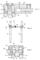
- FIG. 1-4 illustrate a cross-connector assembly 10 for a bone anchoring element, constructed and operative in accordance with an embodiment of the present invention.
- the cross-connector assembly 10 may be constructed of any suitable, medically safe material, such as but not limited to, stainless steel alloy (e.g., AISI 316L), titanium or titanium alloy or chrome cobalt alloy, PEEK, shape memory alloys or polymers, or any combination thereof. Different parts of cross-connector assembly 10 may be constructed of different materials with different resilience or hardness, or of the same material but treated to have different resilience or hardness.
- stainless steel alloy e.g., AISI 316L
- titanium or titanium alloy or chrome cobalt alloy e.g., titanium or titanium alloy or chrome cobalt alloy, PEEK, shape memory alloys or polymers, or any combination thereof.
- PEEK shape memory alloys or polymers
- cross-connector assembly 10 includes a connector element 12 that cooperates with a lug element 14 and pivoting ears 16 for gripping a connecting rod (or other bone anchoring element) 18.
- the connector element 12 is connected to a transverse connector element 20 in a telescoping manner.
- Transverse connector element 20 also cooperates with another lug element 14 and pivoting ears 16 for gripping another connecting rod 18.
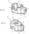
- Connector element 12 includes a receptacle 22 from which extends a neck 24, preferably of smaller cross-sectional shape than receptacle 22.
- Receptacle 22 may be prismatic or rounded in shape and is formed with aligned U-shaped apertures 26 on opposite side walls thereof, a tapped hole 28 on a top portion thereof, and an elongate oval hole 30 on a rounded corner thereof.
- Neck 24 is formed with a (typically blind) hole 32 at an end thereof and a tapped hole 34 on a top portion thereof.
- Transverse connector element 20 includes a receptacle 36 from which extends a transverse rod 38, preferably of smaller cross-sectional shape than receptacle 36.
- Receptacle 36 may be prismatic or rounded in shape and is formed with aligned U-shaped apertures 40 on opposite side walls thereof, a tapped hole 42 on a top portion thereof, and an elongate oval hole 44 on a rounded corner thereof.
- Transverse rod 38 is sized to fit into blind hole 32 of connector element 12.
- Lug element 14 resembles a miniature footstool and is sized to fit in the receptacle 22 of connector element 12 and the receptacle 36 of transverse connector element 20.
- the body of lug element 14 includes a top surface 46 formed with a tapped hole 48.
- Four legs 50 (that is, two pairs of legs) extend from top surface 46.
- Each pair of legs 50 is formed with holes 52 for pivotally pinning thereto the ears 16 with a pin 54 (not shown here but seen in Fig. 3 ), the purpose of which is explained further below.
- An angled hole 56 is formed through the side of lug element 14 near one of the legs 50 and goes through to the bottom of tapped hole 48.
- the cross-connector assembly 10 may be assembled as follows, with reference again to Figs. 1-4 .
- Two ears 16 are pinned to each lug element 14.
- One connector rod 18 is placed between the ears 16 of lug element 14.
- Lug element 14 is placed in receptacle 22 of connector element 12 so that the tapped hole 48 of lug element 14 is aligned with the tapped hole 28 of connector element 12.
- a mechanical fastener (e.g., screw) 58 is screwed into the tapped holes 28 and 48. This pulls lug element 14 towards the top portion of connector element 12, which causes the ears 16 to abut against the inner side walls of connector element 12. This causes the ears 16 to pivot about pins 54 and wrap against connector rod 18.
- ears 16 grip connector rod 18 tightly due to the tightening of lug element 14 with connector element 12.
- a pin 59 may be placed though elongate oval hole 30 into angled hole 56 to further fasten lug element 14 with connector element 12.
- transverse rod 38 of transverse connector element 20 is placed in the blind hole 32 of neck 24 of connector element 12.
- a mechanical fastener (e.g., screw) 60 is then tightened against transverse rod 38 through tapped hole 34 of neck 24.
- transverse rod 38 may be positioned telescopically at any desired position with respect to connector element 12 within the limits of the length of neck 24.
- Figs. 5-7 show another connector element 12 with a longer neck 62 and longer blind hole 64 (like elements being designated by like numerals).
- Neck 24 or longer neck 62 can have partially open sides to allow angular freedom of the transverse rod 38 before locking (not shown).
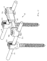
- FIG. 11 illustrates cross-connector assembly 10 connected to connector rods 18, which are connected to bone anchoring elements (pedicle screws) 66.
- the bone anchoring elements 66 may be threaded mechanical fasteners (for example, without limitation, a pedicle screw, a pedicle anchor device, a bone hook, a blocking screw for a pedicle anchoring device or any other device for attachment to the pedicle or others sections of the vertebral bone).
- a pedicle screw for example, without limitation, a pedicle screw, a pedicle anchor device, a bone hook, a blocking screw for a pedicle anchoring device or any other device for attachment to the pedicle or others sections of the vertebral bone.
- FIG. 12-13B illustrate a cross-connector assembly 70 and connector element 72 for a bone anchoring element.
- the connector element 72 is similar to the connector element 12 of cross-connector assembly 10, with like elements being designated by like numerals. Briefly, connector element 72 cooperates with lug element 14 and pivoting ears 16 that pivot about pivots 54 for gripping a connecting rod 18. Mechanical fastener 58 is screwed into tapped holes of a body 74 and lug element 14. This pulls lug element 14 towards the top portion of connector element 72, which causes the ears 16 to abut against the inner side walls of body 74. This causes the ears 16 to pivot about pins 54 and wrap against connector rod 18.
- Cross -connector assembly 70 further includes a washer cap 76 arranged to press against and hold a cross bar 78 or other anchoring element in a recess 79 formed in body 74.
- An O-ring 77 may be disposed on a portion of mechanical fastener 58 for preventing pull-out of fastener 58.
- the recess 79 may be fan-shaped to permit angular (e.g., azimuthal) adjustment of the cross bar or other anchoring element.
- Other fastening arrangements different from the recess 79 and washer cap 76 may be used to hold the cross bar and still permit angular adjustments. Accordingly, cross-connector assembly 70 can be used to hold connecting rods 18 and cross bar 78 at any desired spatial orientation.
- the connector assembly can be used to grip not just a connecting rod but any bone-anchoring element.
- the assembly can be used to directly grip and hold a pedicle screw connector, wherein the head of the screw is designed to fit in and be held by the ears 16 of the cross connector assembly. In this way, the screws are inserted first and then the cross connector is attached to the screw head (or hook or any other anchoring element).
- FIG. 15-16 illustrate a cross-connector assembly 80 for a bone anchoring element.
- Cross-connector assembly 80 includes two transverse connector elements 20, instead of one transverse connector element 20 and one connector element 12.
- the transverse rods 38 of each transverse connector element 20 are linked by a hinged connector 82 that enables angled and telescopic relative movement between the transverse connector elements 20.
- hinged connector 82 includes a plurality of resilient receptacles 84 for receiving therein transverse rods 38.
- the resilient receptacles 84 may be formed from titanium alloy or other suitable material.
- the resilient receptacles 84 may be formed as U-shaped channels whose sides are squeezed together by a mechanical fastener (e.g., screw) 86. Tightening mechanical fastener 86 grips the transverse rods 38 and locks them in a desired orientation.
Landscapes
- Health & Medical Sciences (AREA)
- Orthopedic Medicine & Surgery (AREA)
- Life Sciences & Earth Sciences (AREA)
- Neurology (AREA)
- Surgery (AREA)
- Heart & Thoracic Surgery (AREA)
- Engineering & Computer Science (AREA)
- Biomedical Technology (AREA)
- Nuclear Medicine, Radiotherapy & Molecular Imaging (AREA)
- Medical Informatics (AREA)
- Molecular Biology (AREA)
- Animal Behavior & Ethology (AREA)
- General Health & Medical Sciences (AREA)
- Public Health (AREA)
- Veterinary Medicine (AREA)
- Surgical Instruments (AREA)
- Connector Housings Or Holding Contact Members (AREA)
Claims (11)
- Ensemble (10), comprenant :un élément raccord (12, 20) comprenant un réceptacle (22, 36) dans une partie supérieure duquel est formé un trou (28, 42) ;un élément tenon (14) dimensionné pour s'insérer dans ledit réceptacle (22, 36) dudit élément raccord (12, 20), ledit élément tenon (14) comprenant une surface supérieure (46) dans laquelle est formée un trou taraudé (48) ; dans lequel ledit élément tenon (14) peut être positionné dans ledit réceptacle (22, 36) pour que ledit trou taraudé (48) dudit élément tenon (14) soit aligné sur ledit trou (28, 42) dudit élément raccord (12, 20) ;des pattes (16) raccordées au dit élément tenon (14) ; etune fixation mécanique (58) qui fixe ledit élément raccord (12) conjointement au dit élément tenon (14) ;dans lequel ladite fixation mécanique (58) peut être vissée dans ledit trou taraudé (48), ce qui fait venir lesdites pattes (16) en butée contre les parois latérales intérieures dudit élément raccord (12, 20),entraînant ainsi la préhension par lesdites pattes (16) d'un élément ancrage osseux (18) placé entre lesdites pattes (16), caractérisé en ce que :les pattes (16) sont raccordées pivotantes au dit élément tenon (14) ; en ce quele trou (28, 42) du réceptacle (22, 36) est taraudé ; et en ce queladite fixation mécanique (58) peut être vissée dans ledit trou taraudé (28, 42) du réceptacle (22, 36).
- Ensemble (10) selon la revendication 1, comprenant en outre un élément raccord transversal (20) qui se raccorde au dit élément raccord (12) de manière télescopique.
- Ensemble (10) selon la revendication 2, dans lequel un goulot (24) s'étend à partir dudit réceptacle (22) et dans lequel ledit élément raccord transversal (20) comprend un réceptacle (36) à partir duquel s'étend une tige transversale (38) qui est reçue dans ledit goulot (24) dudit élément raccord (12) de manière télescopique.
- Ensemble (10) selon la revendication 3, comprenant en outre un autre élément tenon (14) dimensionné pour s'insérer dans ledit réceptacle (36) dudit élément raccord transversal (20), dans lequel les pattes (16) sont raccordées pivotantes au dit élément tenon (14), et une autre fixation mécanique (58) qui fixe ledit élément raccord transversal (20) conjointement au dit autre élément tenon (14), entraînant ainsi le pivotement desdites pattes (16) et la préhension par lesdites pattes (16) de l'autre élément ancrage osseux (18) placé entre lesdites pattes (16).
- Ensemble (10) selon la revendication 4, dans lequel lesdits éléments ancrage osseux (18) sont raccordés à d'autres éléments ancrage osseux (66).
- Ensemble (10) selon la revendication 1, dans lequel ledit élément tenon (14) est goupillé au dit élément raccord (12, 20) avec une goupille (59) passant dans un trou incliné (56) formé dans ledit élément tenon (14).
- Ensemble (10) selon la revendication 1, dans lequel ledit élément tenon (14) est goupillé au dit élément raccord transversal (20) avec une goupille (59) passant dans un trou incliné (56) formé dans ledit élément tenon (14).
- Ensemble (10) selon la revendication 1, comprenant en outre une rondelle capuchon (76) disposée pour appuyer contre et maintenir un élément ancrage osseux (78) dans une cavité (79) formée dans un corps (74) dudit élément raccord (72).
- Ensemble (10) selon la revendication 8, dans lequel ladite cavité (79) permet un ajustement angulaire de l'élément ancrage osseux (78) placé dans ladite cavité (79) .
- Ensemble (10) selon la revendication 2, comprenant en outre une pluralité d'éléments raccord transversal (20) raccordés les uns aux autres par un raccord à charnière (82).
- Ensemble (10) selon la revendication 10, dans lequel ledit raccord à charnière (82) permet un mouvement relatif angulaire et télescopique entre lesdits éléments raccord transversal (20).
Applications Claiming Priority (2)
| Application Number | Priority Date | Filing Date | Title |
|---|---|---|---|
| US12/032,721 US8197515B2 (en) | 2008-02-18 | 2008-02-18 | Cross-connector assembly |
| PCT/US2009/034226 WO2009105403A2 (fr) | 2008-02-18 | 2009-02-17 | Ensemble raccord transversal |
Publications (2)
| Publication Number | Publication Date |
|---|---|
| EP2249722A2 EP2249722A2 (fr) | 2010-11-17 |
| EP2249722B1 true EP2249722B1 (fr) | 2016-04-27 |
Family
ID=40911048
Family Applications (1)
| Application Number | Title | Priority Date | Filing Date |
|---|---|---|---|
| EP09711768.3A Not-in-force EP2249722B1 (fr) | 2008-02-18 | 2009-02-17 | Ensemble raccord transversal |
Country Status (3)
| Country | Link |
|---|---|
| US (1) | US8197515B2 (fr) |
| EP (1) | EP2249722B1 (fr) |
| WO (1) | WO2009105403A2 (fr) |
Families Citing this family (50)
| Publication number | Priority date | Publication date | Assignee | Title |
|---|---|---|---|---|
| ATE524121T1 (de) | 2004-11-24 | 2011-09-15 | Abdou Samy | Vorrichtungen zur platzierung eines orthopädischen intervertebralen implantats |
| US7862588B2 (en) | 2005-02-18 | 2011-01-04 | Samy Abdou | Devices and methods for dynamic fixation of skeletal structure |
| US8876874B2 (en) * | 2006-08-21 | 2014-11-04 | M. Samy Abdou | Bone screw systems and methods of use |
| CA2694437C (fr) | 2007-07-26 | 2016-09-06 | Glenn R. Buttermann | Dispositif orthopedique segmentaire pour elongation spinale et pour le traitement de la scoliose |
| US9204908B2 (en) * | 2007-07-26 | 2015-12-08 | Dynamic Spine, Llc | Segmental orthopedic device for spinal elongation and for treatment of scoliosis |
| EP2346424B1 (fr) * | 2008-10-09 | 2016-07-27 | Total Connect Spine, Llc | Ensemble de liaison spinale |
| US8882803B2 (en) | 2009-04-01 | 2014-11-11 | Globus Medical, Inc. | Orthopedic clamp and extension rod |
| US8764806B2 (en) | 2009-12-07 | 2014-07-01 | Samy Abdou | Devices and methods for minimally invasive spinal stabilization and instrumentation |
| EP2579795B1 (fr) | 2010-06-10 | 2018-10-31 | Globus Medical, Inc. | Vis à os plane surbaissée |
| US20120203278A1 (en) * | 2011-02-04 | 2012-08-09 | Warsaw Orthopedic, Inc. | Crosslink Devices for a Growing Spinal Column Segment |
| US9247964B1 (en) * | 2011-03-01 | 2016-02-02 | Nuasive, Inc. | Spinal Cross-connector |
| US9387013B1 (en) | 2011-03-01 | 2016-07-12 | Nuvasive, Inc. | Posterior cervical fixation system |
| US8337530B2 (en) | 2011-03-09 | 2012-12-25 | Zimmer Spine, Inc. | Polyaxial pedicle screw with increased angulation |
| ES2758656T3 (es) * | 2011-04-07 | 2020-05-06 | Blackstone Medical Inc | Abrazadera para dispositivo de conexión cruzada espinal |
| US8845728B1 (en) | 2011-09-23 | 2014-09-30 | Samy Abdou | Spinal fixation devices and methods of use |
| US8758411B1 (en) | 2011-10-25 | 2014-06-24 | Nuvasive, Inc. | Implants and methods for treating spinal disorders |
| US8337532B1 (en) | 2011-12-08 | 2012-12-25 | Spine Wave, Inc. | Methods for percutaneously extending an existing spinal construct |
| US8945186B2 (en) | 2011-12-30 | 2015-02-03 | Blackstone Medical, Inc. | Multi-axial spinal cross connecting device |
| US8556942B2 (en) | 2011-12-30 | 2013-10-15 | Blackstone Medical, Inc. | Occipito-cervical fixation assembly and method for constructing same |
| US20130226240A1 (en) | 2012-02-22 | 2013-08-29 | Samy Abdou | Spinous process fixation devices and methods of use |
| US9510866B2 (en) * | 2012-08-15 | 2016-12-06 | Blackstone Medical, Inc. | Pivoting spinal fixation devices |
| US9198767B2 (en) | 2012-08-28 | 2015-12-01 | Samy Abdou | Devices and methods for spinal stabilization and instrumentation |
| WO2014062942A1 (fr) * | 2012-10-17 | 2014-04-24 | Kspine, Inc. | Systèmes et procédés d'ajustement de correction du rachis |
| US9320617B2 (en) | 2012-10-22 | 2016-04-26 | Cogent Spine, LLC | Devices and methods for spinal stabilization and instrumentation |
| WO2014089337A2 (fr) | 2012-12-05 | 2014-06-12 | Beth Israel Deaconess Medical Center | Systèmes et procédés pour fémoroplastie de rétablissement d'anisotropie |
| US9827020B2 (en) * | 2013-03-14 | 2017-11-28 | Stryker European Holdings I, Llc | Percutaneous spinal cross link system and method |
| US9510875B2 (en) | 2013-03-14 | 2016-12-06 | Stryker European Holdings I, Llc | Systems and methods for percutaneous spinal fusion |
| WO2014172445A1 (fr) | 2013-04-17 | 2014-10-23 | Ebi, Llc | Système de raccordement croisé |
| US20150094769A1 (en) * | 2013-10-01 | 2015-04-02 | Hamid Abbasi | System and method for lengthening an existing spinal support structure |
| US9220541B1 (en) * | 2014-06-26 | 2015-12-29 | Zimmer Spine, Inc. | Transverse connector |
| US9763703B2 (en) | 2015-05-05 | 2017-09-19 | Degen Medical, Inc. | Cross connectors, kits, and methods |
| US10857003B1 (en) | 2015-10-14 | 2020-12-08 | Samy Abdou | Devices and methods for vertebral stabilization |
| US10624679B2 (en) * | 2016-03-29 | 2020-04-21 | Globus Medical, Inc. | Revision connectors, systems and methods thereof |
| US10307185B2 (en) * | 2016-03-29 | 2019-06-04 | Globus Medical, Inc. | Revision connectors, systems, and methods thereof |
| US10321939B2 (en) | 2016-05-18 | 2019-06-18 | Medos International Sarl | Implant connectors and related methods |
| US10517647B2 (en) | 2016-05-18 | 2019-12-31 | Medos International Sarl | Implant connectors and related methods |
| US10973648B1 (en) | 2016-10-25 | 2021-04-13 | Samy Abdou | Devices and methods for vertebral bone realignment |
| US10744000B1 (en) | 2016-10-25 | 2020-08-18 | Samy Abdou | Devices and methods for vertebral bone realignment |
| US10398476B2 (en) | 2016-12-13 | 2019-09-03 | Medos International Sàrl | Implant adapters and related methods |
| US10492835B2 (en) | 2016-12-19 | 2019-12-03 | Medos International Sàrl | Offset rods, offset rod connectors, and related methods |
| US10413331B2 (en) | 2016-12-21 | 2019-09-17 | Spine Wave, Inc. | Spinal stabilization system with head to head cross connector |
| US10238432B2 (en) | 2017-02-10 | 2019-03-26 | Medos International Sàrl | Tandem rod connectors and related methods |
| US10561454B2 (en) | 2017-03-28 | 2020-02-18 | Medos International Sarl | Articulating implant connectors and related methods |
| US10966761B2 (en) | 2017-03-28 | 2021-04-06 | Medos International Sarl | Articulating implant connectors and related methods |
| US10362982B2 (en) | 2017-04-28 | 2019-07-30 | Warsaw Orthopedic, Inc. | Spinal implant system and method |
| CN107296647A (zh) * | 2017-06-16 | 2017-10-27 | 宁德市闽东医院 | 一种适用于微创手术的椎弓根钉横连接固定装置 |
| US11076890B2 (en) | 2017-12-01 | 2021-08-03 | Medos International Sàrl | Rod-to-rod connectors having robust rod closure mechanisms and related methods |
| US11179248B2 (en) | 2018-10-02 | 2021-11-23 | Samy Abdou | Devices and methods for spinal implantation |
| WO2020154435A1 (fr) * | 2019-01-22 | 2020-07-30 | Life Spine, Inc | Support de tige de vis vertébrale polyaxiale comprenant un second support de tige, décalé |
| US20250072939A1 (en) * | 2023-08-29 | 2025-03-06 | Oluwatodimu Richard Raji | Percutaneous Minimally Invasive Cross Connector System |
Citations (1)
| Publication number | Priority date | Publication date | Assignee | Title |
|---|---|---|---|---|
| US20020111625A1 (en) * | 2001-02-12 | 2002-08-15 | Marc Richelsoph | Rod to rod connector |
Family Cites Families (9)
| Publication number | Priority date | Publication date | Assignee | Title |
|---|---|---|---|---|
| WO1999009901A1 (fr) | 1997-08-21 | 1999-03-04 | Synthes Ag Chur | Dispositif pour relier une tige a un autre implant |
| US7485132B1 (en) * | 2000-10-06 | 2009-02-03 | Abbott Spine Inc. | Transverse connector with cam activated engagers |
| FR2835734B1 (fr) | 2002-02-11 | 2004-10-29 | Scient X | Systeme de liaison entre une tige rachidienne et une barre transversale |
| DE10246418A1 (de) | 2002-10-04 | 2004-04-15 | Mtm Medizintechnik Mauk Gmbh | Verbindung von mindestens zwei einander kreuzenden Stäben |
| US20050228377A1 (en) * | 2004-04-07 | 2005-10-13 | Depuy Spine, Inc. | Spinal cross-connectors |
| US7594924B2 (en) * | 2005-03-03 | 2009-09-29 | Accelerated Innovation, Llc | Spinal stabilization using bone anchor seat and cross coupling with improved locking feature |
| EP1931269A1 (fr) * | 2005-10-07 | 2008-06-18 | Alphatec Spine, Inc. | Raccord de tiges tranversal |
| US7837714B2 (en) | 2006-04-10 | 2010-11-23 | Warsaw Orthopedic, Inc. | Methods and devices for the interconnection of bone attachment devices |
| US7942900B2 (en) * | 2007-06-05 | 2011-05-17 | Spartek Medical, Inc. | Shaped horizontal rod for dynamic stabilization and motion preservation spinal implantation system and method |
-
2008
- 2008-02-18 US US12/032,721 patent/US8197515B2/en active Active
-
2009
- 2009-02-17 EP EP09711768.3A patent/EP2249722B1/fr not_active Not-in-force
- 2009-02-17 WO PCT/US2009/034226 patent/WO2009105403A2/fr not_active Ceased
Patent Citations (1)
| Publication number | Priority date | Publication date | Assignee | Title |
|---|---|---|---|---|
| US20020111625A1 (en) * | 2001-02-12 | 2002-08-15 | Marc Richelsoph | Rod to rod connector |
Also Published As
| Publication number | Publication date |
|---|---|
| US20090210007A1 (en) | 2009-08-20 |
| WO2009105403A3 (fr) | 2009-10-15 |
| WO2009105403A2 (fr) | 2009-08-27 |
| EP2249722A2 (fr) | 2010-11-17 |
| US8197515B2 (en) | 2012-06-12 |
Similar Documents
| Publication | Publication Date | Title |
|---|---|---|
| EP2249722B1 (fr) | Ensemble raccord transversal | |
| US12053211B2 (en) | Posterior cervical fixation system | |
| AU770026B2 (en) | Spinal cross connector | |
| US9131963B2 (en) | Posterior cross connector assembly | |
| US20080269742A1 (en) | Connector assembly for bone anchoring element | |
| US5645544A (en) | Variable angle extension rod | |
| CN100444809C (zh) | 用于结合脊椎杆的联结横向连接器 | |
| US8226689B2 (en) | Apparatus and methods for spinal implant with variable link mechanism | |
| US7377922B2 (en) | Transfer ring for offset tapered 3D connector | |
| US7789900B2 (en) | Double collet connector assembly for bone anchoring element | |
| EP2693965B1 (fr) | Pince pour dispositif d'interconnexion de colonne vertébrale | |
| US20080183223A1 (en) | Hybrid jointed bone screw system | |
| US20040133203A1 (en) | Multi-axial, cross-link connector system for spinal implants | |
| US20090264926A1 (en) | Spinal Fixation System | |
| JP2010506684A (ja) | 中央ロッドコネクタとt字ロッド | |
| WO2007130840A1 (fr) | Dispositif et procédé de verrouillage destinés à être utilisés dans un système de stabilisation osseuse, mettant en oeuvre un organe à vis de fixation et un organe à selle déformable | |
| CA2503116A1 (fr) | Systeme de raccord multiaxial par interaction pour implants vertebraux | |
| US20090105755A1 (en) | Apparatus and method for connecting spinal fixation systems together | |
| US10874441B2 (en) | Occipital-cervical fixation equipment | |
| EP2079378A2 (fr) | Système de plaque orthopédique |
Legal Events
| Date | Code | Title | Description |
|---|---|---|---|
| PUAI | Public reference made under article 153(3) epc to a published international application that has entered the european phase |
Free format text: ORIGINAL CODE: 0009012 |
|
| 17P | Request for examination filed |
Effective date: 20100812 |
|
| AK | Designated contracting states |
Kind code of ref document: A2 Designated state(s): AT BE BG CH CY CZ DE DK EE ES FI FR GB GR HR HU IE IS IT LI LT LU LV MC MK MT NL NO PL PT RO SE SI SK TR |
|
| AX | Request for extension of the european patent |
Extension state: AL BA RS |
|
| DAX | Request for extension of the european patent (deleted) | ||
| 17Q | First examination report despatched |
Effective date: 20150129 |
|
| GRAP | Despatch of communication of intention to grant a patent |
Free format text: ORIGINAL CODE: EPIDOSNIGR1 |
|
| INTG | Intention to grant announced |
Effective date: 20160108 |
|
| GRAS | Grant fee paid |
Free format text: ORIGINAL CODE: EPIDOSNIGR3 |
|
| GRAA | (expected) grant |
Free format text: ORIGINAL CODE: 0009210 |
|
| AK | Designated contracting states |
Kind code of ref document: B1 Designated state(s): AT BE BG CH CY CZ DE DK EE ES FI FR GB GR HR HU IE IS IT LI LT LU LV MC MK MT NL NO PL PT RO SE SI SK TR |
|
| REG | Reference to a national code |
Ref country code: GB Ref legal event code: FG4D |
|
| REG | Reference to a national code |
Ref country code: CH Ref legal event code: EP |
|
| REG | Reference to a national code |
Ref country code: AT Ref legal event code: REF Ref document number: 793866 Country of ref document: AT Kind code of ref document: T Effective date: 20160515 |
|
| REG | Reference to a national code |
Ref country code: IE Ref legal event code: FG4D |
|
| REG | Reference to a national code |
Ref country code: DE Ref legal event code: R096 Ref document number: 602009038191 Country of ref document: DE |
|
| REG | Reference to a national code |
Ref country code: LT Ref legal event code: MG4D |
|
| REG | Reference to a national code |
Ref country code: NL Ref legal event code: MP Effective date: 20160427 |
|
| REG | Reference to a national code |
Ref country code: AT Ref legal event code: MK05 Ref document number: 793866 Country of ref document: AT Kind code of ref document: T Effective date: 20160427 |
|
| PG25 | Lapsed in a contracting state [announced via postgrant information from national office to epo] |
Ref country code: NL Free format text: LAPSE BECAUSE OF FAILURE TO SUBMIT A TRANSLATION OF THE DESCRIPTION OR TO PAY THE FEE WITHIN THE PRESCRIBED TIME-LIMIT Effective date: 20160427 |
|
| PG25 | Lapsed in a contracting state [announced via postgrant information from national office to epo] |
Ref country code: PL Free format text: LAPSE BECAUSE OF FAILURE TO SUBMIT A TRANSLATION OF THE DESCRIPTION OR TO PAY THE FEE WITHIN THE PRESCRIBED TIME-LIMIT Effective date: 20160427 Ref country code: FI Free format text: LAPSE BECAUSE OF FAILURE TO SUBMIT A TRANSLATION OF THE DESCRIPTION OR TO PAY THE FEE WITHIN THE PRESCRIBED TIME-LIMIT Effective date: 20160427 Ref country code: NO Free format text: LAPSE BECAUSE OF FAILURE TO SUBMIT A TRANSLATION OF THE DESCRIPTION OR TO PAY THE FEE WITHIN THE PRESCRIBED TIME-LIMIT Effective date: 20160727 Ref country code: LT Free format text: LAPSE BECAUSE OF FAILURE TO SUBMIT A TRANSLATION OF THE DESCRIPTION OR TO PAY THE FEE WITHIN THE PRESCRIBED TIME-LIMIT Effective date: 20160427 |
|
| PG25 | Lapsed in a contracting state [announced via postgrant information from national office to epo] |
Ref country code: PT Free format text: LAPSE BECAUSE OF FAILURE TO SUBMIT A TRANSLATION OF THE DESCRIPTION OR TO PAY THE FEE WITHIN THE PRESCRIBED TIME-LIMIT Effective date: 20160829 Ref country code: ES Free format text: LAPSE BECAUSE OF FAILURE TO SUBMIT A TRANSLATION OF THE DESCRIPTION OR TO PAY THE FEE WITHIN THE PRESCRIBED TIME-LIMIT Effective date: 20160427 Ref country code: LV Free format text: LAPSE BECAUSE OF FAILURE TO SUBMIT A TRANSLATION OF THE DESCRIPTION OR TO PAY THE FEE WITHIN THE PRESCRIBED TIME-LIMIT Effective date: 20160427 Ref country code: AT Free format text: LAPSE BECAUSE OF FAILURE TO SUBMIT A TRANSLATION OF THE DESCRIPTION OR TO PAY THE FEE WITHIN THE PRESCRIBED TIME-LIMIT Effective date: 20160427 Ref country code: HR Free format text: LAPSE BECAUSE OF FAILURE TO SUBMIT A TRANSLATION OF THE DESCRIPTION OR TO PAY THE FEE WITHIN THE PRESCRIBED TIME-LIMIT Effective date: 20160427 Ref country code: SE Free format text: LAPSE BECAUSE OF FAILURE TO SUBMIT A TRANSLATION OF THE DESCRIPTION OR TO PAY THE FEE WITHIN THE PRESCRIBED TIME-LIMIT Effective date: 20160427 Ref country code: GR Free format text: LAPSE BECAUSE OF FAILURE TO SUBMIT A TRANSLATION OF THE DESCRIPTION OR TO PAY THE FEE WITHIN THE PRESCRIBED TIME-LIMIT Effective date: 20160728 |
|
| PG25 | Lapsed in a contracting state [announced via postgrant information from national office to epo] |
Ref country code: BE Free format text: LAPSE BECAUSE OF FAILURE TO SUBMIT A TRANSLATION OF THE DESCRIPTION OR TO PAY THE FEE WITHIN THE PRESCRIBED TIME-LIMIT Effective date: 20160427 Ref country code: IT Free format text: LAPSE BECAUSE OF FAILURE TO SUBMIT A TRANSLATION OF THE DESCRIPTION OR TO PAY THE FEE WITHIN THE PRESCRIBED TIME-LIMIT Effective date: 20160427 |
|
| REG | Reference to a national code |
Ref country code: DE Ref legal event code: R097 Ref document number: 602009038191 Country of ref document: DE |
|
| PG25 | Lapsed in a contracting state [announced via postgrant information from national office to epo] |
Ref country code: CZ Free format text: LAPSE BECAUSE OF FAILURE TO SUBMIT A TRANSLATION OF THE DESCRIPTION OR TO PAY THE FEE WITHIN THE PRESCRIBED TIME-LIMIT Effective date: 20160427 Ref country code: DK Free format text: LAPSE BECAUSE OF FAILURE TO SUBMIT A TRANSLATION OF THE DESCRIPTION OR TO PAY THE FEE WITHIN THE PRESCRIBED TIME-LIMIT Effective date: 20160427 Ref country code: EE Free format text: LAPSE BECAUSE OF FAILURE TO SUBMIT A TRANSLATION OF THE DESCRIPTION OR TO PAY THE FEE WITHIN THE PRESCRIBED TIME-LIMIT Effective date: 20160427 Ref country code: SK Free format text: LAPSE BECAUSE OF FAILURE TO SUBMIT A TRANSLATION OF THE DESCRIPTION OR TO PAY THE FEE WITHIN THE PRESCRIBED TIME-LIMIT Effective date: 20160427 Ref country code: RO Free format text: LAPSE BECAUSE OF FAILURE TO SUBMIT A TRANSLATION OF THE DESCRIPTION OR TO PAY THE FEE WITHIN THE PRESCRIBED TIME-LIMIT Effective date: 20160427 |
|
| REG | Reference to a national code |
Ref country code: FR Ref legal event code: PLFP Year of fee payment: 9 |
|
| PLBE | No opposition filed within time limit |
Free format text: ORIGINAL CODE: 0009261 |
|
| STAA | Information on the status of an ep patent application or granted ep patent |
Free format text: STATUS: NO OPPOSITION FILED WITHIN TIME LIMIT |
|
| 26N | No opposition filed |
Effective date: 20170130 |
|
| PGFP | Annual fee paid to national office [announced via postgrant information from national office to epo] |
Ref country code: DE Payment date: 20170227 Year of fee payment: 9 Ref country code: FR Payment date: 20170220 Year of fee payment: 9 |
|
| PG25 | Lapsed in a contracting state [announced via postgrant information from national office to epo] |
Ref country code: SI Free format text: LAPSE BECAUSE OF FAILURE TO SUBMIT A TRANSLATION OF THE DESCRIPTION OR TO PAY THE FEE WITHIN THE PRESCRIBED TIME-LIMIT Effective date: 20160427 |
|
| PG25 | Lapsed in a contracting state [announced via postgrant information from national office to epo] |
Ref country code: MC Free format text: LAPSE BECAUSE OF FAILURE TO SUBMIT A TRANSLATION OF THE DESCRIPTION OR TO PAY THE FEE WITHIN THE PRESCRIBED TIME-LIMIT Effective date: 20160427 |
|
| REG | Reference to a national code |
Ref country code: CH Ref legal event code: PL |
|
| GBPC | Gb: european patent ceased through non-payment of renewal fee |
Effective date: 20170217 |
|
| PG25 | Lapsed in a contracting state [announced via postgrant information from national office to epo] |
Ref country code: LI Free format text: LAPSE BECAUSE OF NON-PAYMENT OF DUE FEES Effective date: 20170228 Ref country code: CH Free format text: LAPSE BECAUSE OF NON-PAYMENT OF DUE FEES Effective date: 20170228 |
|
| REG | Reference to a national code |
Ref country code: IE Ref legal event code: MM4A |
|
| PG25 | Lapsed in a contracting state [announced via postgrant information from national office to epo] |
Ref country code: LU Free format text: LAPSE BECAUSE OF NON-PAYMENT OF DUE FEES Effective date: 20170217 |
|
| PG25 | Lapsed in a contracting state [announced via postgrant information from national office to epo] |
Ref country code: GB Free format text: LAPSE BECAUSE OF NON-PAYMENT OF DUE FEES Effective date: 20170217 Ref country code: IE Free format text: LAPSE BECAUSE OF NON-PAYMENT OF DUE FEES Effective date: 20170217 |
|
| REG | Reference to a national code |
Ref country code: DE Ref legal event code: R119 Ref document number: 602009038191 Country of ref document: DE |
|
| PG25 | Lapsed in a contracting state [announced via postgrant information from national office to epo] |
Ref country code: MT Free format text: LAPSE BECAUSE OF NON-PAYMENT OF DUE FEES Effective date: 20170217 |
|
| REG | Reference to a national code |
Ref country code: FR Ref legal event code: ST Effective date: 20181031 |
|
| PG25 | Lapsed in a contracting state [announced via postgrant information from national office to epo] |
Ref country code: DE Free format text: LAPSE BECAUSE OF NON-PAYMENT OF DUE FEES Effective date: 20180901 |
|
| PG25 | Lapsed in a contracting state [announced via postgrant information from national office to epo] |
Ref country code: FR Free format text: LAPSE BECAUSE OF NON-PAYMENT OF DUE FEES Effective date: 20180228 |
|
| PG25 | Lapsed in a contracting state [announced via postgrant information from national office to epo] |
Ref country code: HU Free format text: LAPSE BECAUSE OF FAILURE TO SUBMIT A TRANSLATION OF THE DESCRIPTION OR TO PAY THE FEE WITHIN THE PRESCRIBED TIME-LIMIT; INVALID AB INITIO Effective date: 20090217 |
|
| PG25 | Lapsed in a contracting state [announced via postgrant information from national office to epo] |
Ref country code: BG Free format text: LAPSE BECAUSE OF FAILURE TO SUBMIT A TRANSLATION OF THE DESCRIPTION OR TO PAY THE FEE WITHIN THE PRESCRIBED TIME-LIMIT Effective date: 20160427 |
|
| PG25 | Lapsed in a contracting state [announced via postgrant information from national office to epo] |
Ref country code: CY Free format text: LAPSE BECAUSE OF NON-PAYMENT OF DUE FEES Effective date: 20160427 |
|
| PG25 | Lapsed in a contracting state [announced via postgrant information from national office to epo] |
Ref country code: MK Free format text: LAPSE BECAUSE OF FAILURE TO SUBMIT A TRANSLATION OF THE DESCRIPTION OR TO PAY THE FEE WITHIN THE PRESCRIBED TIME-LIMIT Effective date: 20160427 |
|
| PG25 | Lapsed in a contracting state [announced via postgrant information from national office to epo] |
Ref country code: TR Free format text: LAPSE BECAUSE OF FAILURE TO SUBMIT A TRANSLATION OF THE DESCRIPTION OR TO PAY THE FEE WITHIN THE PRESCRIBED TIME-LIMIT Effective date: 20160427 |
|
| PG25 | Lapsed in a contracting state [announced via postgrant information from national office to epo] |
Ref country code: IS Free format text: LAPSE BECAUSE OF FAILURE TO SUBMIT A TRANSLATION OF THE DESCRIPTION OR TO PAY THE FEE WITHIN THE PRESCRIBED TIME-LIMIT Effective date: 20160827 |