EP2249731B1 - Chirurgisches magnetisches target-system - Google Patents
Chirurgisches magnetisches target-system Download PDFInfo
- Publication number
- EP2249731B1 EP2249731B1 EP08730366.5A EP08730366A EP2249731B1 EP 2249731 B1 EP2249731 B1 EP 2249731B1 EP 08730366 A EP08730366 A EP 08730366A EP 2249731 B1 EP2249731 B1 EP 2249731B1
- Authority
- EP
- European Patent Office
- Prior art keywords
- magnetic
- targeting
- extender
- targeting system
- biocompatible device
- Prior art date
- Legal status (The legal status is an assumption and is not a legal conclusion. Google has not performed a legal analysis and makes no representation as to the accuracy of the status listed.)
- Active
Links
Images


Classifications
-
- A—HUMAN NECESSITIES
- A61—MEDICAL OR VETERINARY SCIENCE; HYGIENE
- A61B—DIAGNOSIS; SURGERY; IDENTIFICATION
- A61B17/00—Surgical instruments, devices or methods
- A61B17/56—Surgical instruments or methods for treatment of bones or joints; Devices specially adapted therefor
- A61B17/58—Surgical instruments or methods for treatment of bones or joints; Devices specially adapted therefor for osteosynthesis, e.g. bone plates, screws or setting implements
- A61B17/68—Internal fixation devices, including fasteners and spinal fixators, even if a part thereof projects from the skin
- A61B17/70—Spinal positioners or stabilisers, e.g. stabilisers comprising fluid filler in an implant
- A61B17/7074—Tools specially adapted for spinal fixation operations other than for bone removal or filler handling
- A61B17/7083—Tools for guidance or insertion of tethers, rod-to-anchor connectors, rod-to-rod connectors, or longitudinal elements
- A61B17/7085—Tools for guidance or insertion of tethers, rod-to-anchor connectors, rod-to-rod connectors, or longitudinal elements for insertion of a longitudinal element down one or more hollow screw or hook extensions, i.e. at least a part of the element within an extension has a component of movement parallel to the extension's axis
-
- A—HUMAN NECESSITIES
- A61—MEDICAL OR VETERINARY SCIENCE; HYGIENE
- A61B—DIAGNOSIS; SURGERY; IDENTIFICATION
- A61B17/00—Surgical instruments, devices or methods
- A61B17/56—Surgical instruments or methods for treatment of bones or joints; Devices specially adapted therefor
- A61B17/58—Surgical instruments or methods for treatment of bones or joints; Devices specially adapted therefor for osteosynthesis, e.g. bone plates, screws or setting implements
- A61B17/88—Osteosynthesis instruments; Methods or means for implanting or extracting internal or external fixation devices
- A61B17/90—Guides therefor
-
- A—HUMAN NECESSITIES
- A61—MEDICAL OR VETERINARY SCIENCE; HYGIENE
- A61B—DIAGNOSIS; SURGERY; IDENTIFICATION
- A61B17/00—Surgical instruments, devices or methods
- A61B17/56—Surgical instruments or methods for treatment of bones or joints; Devices specially adapted therefor
- A61B17/58—Surgical instruments or methods for treatment of bones or joints; Devices specially adapted therefor for osteosynthesis, e.g. bone plates, screws or setting implements
- A61B17/68—Internal fixation devices, including fasteners and spinal fixators, even if a part thereof projects from the skin
- A61B17/70—Spinal positioners or stabilisers, e.g. stabilisers comprising fluid filler in an implant
- A61B17/7001—Screws or hooks combined with longitudinal elements which do not contact vertebrae
- A61B17/7032—Screws or hooks with U-shaped head or back through which longitudinal rods pass
-
- A—HUMAN NECESSITIES
- A61—MEDICAL OR VETERINARY SCIENCE; HYGIENE
- A61B—DIAGNOSIS; SURGERY; IDENTIFICATION
- A61B17/00—Surgical instruments, devices or methods
- A61B17/00234—Surgical instruments, devices or methods for minimally invasive surgery
- A61B2017/00292—Surgical instruments, devices or methods for minimally invasive surgery mounted on or guided by flexible, e.g. catheter-like, means
- A61B2017/003—Steerable
Definitions
- the invention generally relates to surgical implants; particularly to a system for stabilization of adjacent bony structures; most particularly to a system to help navigate an interconnecting means between multiple bony stabilization devices.
- an abnormal spine can be stabilized using a substantially rigid or semi-rigid interconnecting means (rod or plate) and fastening means (screws, clamps, hooks, claws, anchors, or bolts).
- fastening means screws, clamps, hooks, claws, anchors, or bolts.
- Multiple fasteners are placed into the spinal pedicle of each vertebra and linked by at least one interconnecting means.
- One of the more difficult aspects is the surgical insertion of the interconnecting means along a fixed path of delivery longitudinally along the vertebrae and through each of the multiple fastening means between multiple vertebrae. Once in place, this system substantially immobilizes the spine and promotes bony fusion (arthrodesis).
- the SEXTANT Spinal system by Medtronic (Memphis, TN).
- This device is comprised of two basic components, screw extenders, and the rod inserter, which results in an instrument that looks like a sextant used in naval navigation.
- the device is an insertion tool that allows fasteners and interconnecting means to be applied to the spine in a minimally invasive manner.
- the screw extenders are long shafts used to deliver and attach screws to the vertebrae through small skin incisions. During surgery, these extenders protrude outside the body, allowing the surgeon to arrange and join their ends so that the rod inserter may be attached.
- the rod inserter is an arc-shaped arm that swings along a fixed axis and pushes an interconnecting rod though the skin and muscle and into the heads of the implanted fasteners (pedicle screws).
- image-based navigation systems In order to help avoid damaging sensitive anatomy and expedite implant assembly, various image-based navigation systems have been employed which utilize patient images obtained prior to or during the medical procedure to guide a surgeon during the surgery. Recent advances in imaging technology have produced detailed two and three dimensional images using optically guided, fluoroscopic guided, and electromagnetic field based systems. These image-based systems have also been used in combination with the previously described "open" surgeries.
- One significant problem with most image-based systems is that the radiation generated is transmitted to the patient and surgical staff, which may result in physiological damage over time. Also, the cost and portability of this equipment continue to be an issue. In addition, these systems often require the surgeon undergo extensive training to operate correctly.
- U.S. Publication No. 2005/0085714 to Foley et al . discloses a method and apparatus for percutaneous and/or minimally invasive implantation of a construct (e.g., spinal implant).
- the construct may be implanted using a navigation system for planning and execution of a procedure.
- a plurality of portions of the construct may be interconnected using locations and paths determined and navigated with the navigation system.
- the navigation system utilizes optical or electromagnetic localization to determine the precise location of a selected implant construct or instrument.
- An optical localizer can be positioned relative to an extender attached to a screw.
- a coil may be positioned in an electromagnetic (EM) field such that the position of the coil may be determined by sensing the induced voltage.
- EM electromagnetic
- a computer is used to form a plan prior to implantation of the construct and thereafter track the various portions of the construct during insertion. The plan and the tracking of the surgery are displayed on a monitor to provide guidance to the surgeon.
- U.S. Publication No. 2005/0277934 to Vardiman discloses a minimally invasive spinal fixation system used for spinal arthrodesis (bony fusion) or motion preservation.
- the system comprises a plurality of pedicle screws, including a first screw placed into a first vertebral body, and a second screw placed into a second vertebral body, a connector for attaching to the first and second screws and, a removable guide for percutaneously attaching the connector to the first and second screws.
- detectional spheres are positioned on the head of screw extenders and on the handle of the rod insertion tool.
- a comparator calculates the relative position of the insertion tool handle with respect to the screw extenders and provides a visual display for the surgeon.
- U.S. Patent No. 6,236,875 to Bucholz discloses surgical navigation systems including reference and localization frames.
- the system generates an image representing the position of one or more body elements during the procedure using magnetic resonance imaging (hereinafter, MRI) or computed tomography (hereinafter, CT) scan images taken prior to the surgery.
- MRI magnetic resonance imaging
- CT computed tomography
- the body elements and their relative position are identified during the procedure.
- the position of the known body elements can then be manipulated using a computer to the relative position of the patient during the surgery.
- the manipulated data can then be utilized to guide the surgeon for implantation.
- U.S. Patent No. 6,226,548 to Foley et al. discloses an apparatus and procedures for percutaneous placement of surgical implants and instruments such as, for example, screws, rods, wires and plates into various body parts using image guided surgery.
- the invention includes an apparatus for use with a surgical navigation system, an attaching device rigidly connected to a body part, such as the spinous process of a vertebra, with an identification superstructure rigidly but removably connected to the attaching device.
- This identification superstructure for example, is a reference arc and fiducial array which accomplishes the function of identifying the location of the superstructure, and, therefore, the body part to which it is fixed, during imaging by CT scan or MRI, and later during medical procedures.
- the system utilizes emitters such as light emitting diodes (hereinafter, LEDs), passive reflective spheres, acoustics, magnetics, electromagnetics, radiologic, or micro-pulsed radars for indicating the location of a body part to which the emitter is attached.
- LEDs light emitting diodes
- passive reflective spheres acoustics
- magnetics magnetics
- electromagnetics radiologic
- micro-pulsed radars for indicating the location of a body part to which the emitter is attached.
- U.S. Patent No. 7,011,660 to Sherman et al. discloses a brace installation instrument and method for the stabilization of bony structures.
- the installation instrument is sextant-type tool with anchor extensions coupled to the anchors.
- the instrument is movable with respect to the anchors to position a brace in a position proximate to the anchors.
- the brace can be indexed for insertion at a predetermined orientation with respect to the installation instrument.
- US 2007/239159 discloses a home screw including a magnetic material in a head portion thereof intended to assist in guiding an extender ("rod”) into an attachment configuration with the home screw.
- US 2007/213714 discloses the innovation of a connecting element into a plurality of anchor members (bone screws) each having an extender.
- Guidance means may be used to identify the subcutaneous position of the connecting member.
- an in vivo magnetic targeting system as defined in claim 1.
- Preferred embodiments are defined in the dependent claims. Associated methods are also described herein to aid understanding of the invention, but these do not form part of the claimed invention.
- the instant invention includes a magnetic targeting system suitable for guiding a biocompatible device, (implant, surgical instrument) to a target area within the body ( in vivo ), be it a tumor or implantation point for a fastening means.
- the system includes a targeting member that includes a steering material. The targeting member is attached at one end to the biocompatible device.
- the system also includes at least one anchoring member constructed and arranged to secure to a target area in vivo at one end and the other end constructed and arranged for inclusion of a magnetic material effective for influencing the traversal of the steering material in vivo.
- the magnetically influenced anchoring member interacts with the steering material of the targeting member such that the connected biocompatible device is positionable relative to the target area.
- Yet another objective of the present invention is to disclose a feedback system that utilizes audio and/or tactile feedback to indicate to the surgeon when the target area is reached.
- Another objective of the present invention is to provide a magnetic targeting system that can penetrate tissue without being distorted or causing physiologic damage, unlike x-rays.
- Still a further objective of the invention is to teach a targeting system which allows for shorter surgery, decreased x-ray exposure, and fewer complications for the patient.
- Yet another objective of the instant invention is to provide a targeting system that is simple to operate to reduce the training the surgeon must undergo for operation of peripheral systems.
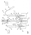
- FIG. 1 shows a plurality of anchoring members 14 (also referred to as fastening means).
- the anchoring members are depicted here as multi-axial pedicle screws, each removably attached to an extender 12a , 12b, 12c. These screws have a proximal end 16 and a distal end 18.
- the proximal end includes head portion 24 with a tool opening 26 configured to receive a driving tool (not shown).
- the distal end includes a threaded shank designed to secure to a selected target area located inside the body of a patient ( in vivo ), shown here as consecutive spinal vertebrae V1, V2, V3.
- a selected target area located inside the body of a patient ( in vivo ), shown here as consecutive spinal vertebrae V1, V2, V3.
- the target area is exemplified here as vertebrae in a partial spinal column the target area may be located anywhere in vivo.
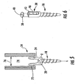
- the screw shown here is a multi-axial screw where the proximal end of the screw may include a connector 28 rotatably connected to the head portion 24 of the screw. That is, the connector is capable of 360 degree rotation relative to the threaded shank 27 of the screw along the axis L of the shank and angular motion defined by the angle ⁇ ( Fig. 5 ).
- a suitable multi-axial screw is described in U.S. Patent No. 5,797,911 , herein incorporated by reference.
- a multi-axis is exemplified herein, it is contemplated that a fixed axis screw may be used. Fixed-axis screws do not include a rotatable connector 28.
- Other means for anchoring are also contemplated herein, some of which include, clamps, hooks, claws, bolts, or the like.
- the shank of the anchor member may or may be not be cannulated, as is known in the art.
- the connector portion of the screw is constructed and arranged to form a passageway 30 designed to removably receive implants of various sizes.
- the connector portion includes an opening 43 constructed and arranged to receive a set screw 38.
- the head portion includes threaded interior sidewalls 46 designed to mate with external threads 38 formed on the set screw.
- the passageway 30 in the connector is narrowed.
- the passageway is narrowed until the exterior surfaces of the biocompatible device 44 (shown here as interconnecting rod, see FIGS. 1-4 ) are sandwiched between the upper portion of the screw head 24 and the set screw. This acts to reliably secure the biocompatible device onto the screw.
- a tool opening 40 configured to receive a driving tool (not shown) inserted within the interior portion 74 of the extenders.
- the driving tool is well known in the surgical arts and is used to rotatably secure the set screw to the desired position within the interior of the connector.
- each of the hollow extenders 12a , 12b, 12c are removably attached to the screws by any appropriate means known in the art.
- the extender may include a depressible member (not shown) located at the proximal end 33 of the extender that is operatively connected to an internal clamping member located that the distal thereof.
- the clamping member is capable of engaging and disengaging the connector portion of the screw.
- a suitable extender which could be used in the present invention is disclosed in U.S. Patent No. 7,011,660 , herein incorporated by reference.
- the extender may also be able to rotate the connector of a multi-axial screw relative to the shank to facilitate the threading of the interconnecting rod therethrough.
- the extenders should be made of a substantially rigid biocompatible material and have a length dimension (along its longitudinal axis 50 ) that allows the proximal end 33 to protrude a distance outside of the percutaneous exposure 22 created through the outer skin S of the patient.
- at least the first extender should have a "c-shape", as seen along an axis transverse its longitudinal axis, thereby defining a slot 63 that extends along its longitudinal axis 50 and into the patient when attached to the screw.
- the slot should be sized to allow the targeting member to exit, so that it is able to be delivered percutaneously, as shown in FIG. 1 .
- the interior dimension 76 of the extenders should be such that they are capable of receiving the appropriate driving tool (not shown) used to engage the screws and set screws.
- the interior dimension of the extenders should be able to accept a removable magnetic device 60 for magnetically influencing the anchor members 14, as described further below.
- a targeting member is shown attached to biocompatible device 44 by a tethering means 42.
- the targeting member has a first end 52 and a second end 54.
- the first end is designed to penetrate the tissue and is shaped to enlarge the opening while creating a pathway through the tissues as the targeting member is advanced in vivo.
- At least the first end of the targeting member is composed of a steering material capable of being magnetically influenced, as described hereafter.
- the targeting member 20 may be made from a flexible, semi-rigid, or rigid material, each includes the steering material 84 located on the first end.
- FIG. 7a illustrates an embodiment of a semi-rigid targeting member in the form of rod-like member with steering material 84 disposed on its first end 52.
- the first portion 78 of the rod is made of a flexible material capable of safely colliding with bony or neural obstructions without causing damage.
- Fig. 7b illustrates another flexible rod formed of a plurality of rigid consecutive segments 80 through which the tethering means 42 extends to the first end (not shown).
- FIG. 7d illustrates another embodiment wherein the targeting member includes a ball joint 88 attached to the tethering means.
- the tension in the tethering member controls the amount of pivot at the ball joint.
- the rod is solid again. This way the surgeon is able to safely guide the targeting member around neural and bony obstructions as it moves through the body.
- FIG. 7e depicts a rigid rod-like member formed from a solid biocompatible material 90.
- the tethering means 42 may be made of any flexible or semi-flexible biocompatible material capable of allowing the device to navigate around neural and bony obstructions without damaging them.
- suitable tethering means may be in the form of a cable, cord or ligament.
- the tethering means may be formed of a cannulated or solid member.
- the first end 92 of the tethering means is attached to the second end 54 of the targeting member by any means of attachment known in the art.
- the second end 94 of the tethering means is attached to the biocompatible device 44 by any means of removable connection known in the art.
- the biocompatible device and tethering means could include corresponding threads that the surgeon can rotate to disconnect the tethering means from the biocompatible device.
- the biocompatible device is shown as an implantable interconnecting rod.
- the rod may be rigid, semi-rigid or flexible. Rigid rods are usually preferred for providing the necessary stability during the healing process and arthrodesis, however, flexible rods have been found to provide for arthrodesis while allowing some movement between bony structures that have been interconnected to preserve some motion.
- the biocompatible device may also be solid or cannulated.
- interconnecting rod is shown in FIGS 1-4 as interconnecting two pedicle screws, the surgeon could use any appropriately sized rod having a length dimension capable of interconnecting three or more fastening means co-linearly implanted along multiple vertebrae. It is also within in the purview of the invention that any sized rod having various widths or diameters could be used so long as it is capable of stabilizing the bony structures for bony fusion.
- a rod-like member is exemplified herein, other such biocompatible devices known to one skilled in the art are also contemplated, for example, plates, clamps, etc.
- FIG. 4 illustrates a hollow or cannulated flexible biocompatible device in fluid communication with a cannulated tethering means.
- the surgeon can use an insertion means 96 (syringe or the like) to supply a biocompatible hardening material (e.g., cement, carbon, bone matrix) through the tethering means and into the interior of the hollow rod.
- a biocompatible hardening material e.g., cement, carbon, bone matrix
- the biocompatible device might also be made permeable and used to deliver constituents supplied by the insertion means to the target area (e.g., bone growth/fusion material, medication, curing material, etc.).
- each of the proximal ends of the extenders 12a-c protrude outside of the patient's skin through percutaneous incisions 22 so that the surgeon is able to insert instrumentation through the extender's interior portion to access the screw secured to the target area (vertebra).
- the extenders also enable the surgeon to insert the magnetic device or wand 60 into the selected extender to a position proximate the corresponding anchor 14.
- the magnetic device includes a proximal 64 and a distal end 66. Magnetic material 62 is attached at the distal end of the device and the proximal end may include a grip 100 (not required) for the surgeon to hold the magnetic device.
- the wand should be sized to extend the length of the extender.
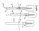
- the "magnetic material” 62 as used herein refers to either a permanent magnet (as shown in FIG. 9) or an electromagnet (shown in FIGS. 1-4 ) which generates a magnetic field capable of influencing the steering material in the targeting member in vivo.
- an electromagnet is a magnet in which the magnetic field is produced by a flow of electrical current.
- a suitable permanent magnet is a Neodymium Iron Boron (NdFeB) magnet since it is powerful and has been approved by the U.S. Food and Drug Administration (FDA) for internal use.
- PANiCNQ emeraldine-base polyanailine
- TCNQ tetracyanquinodimethane
- the "steering" material in the target member refers to any material capable of being influenced by the magnetic material 62.
- the steering material may include any magnetically attractive material or alloy, (e.g. steel, iron, etc).
- the steering material may be the same or different than that used for magnetic material 62 so long as it is capable of being influenced, e.g., attracted or repelled.
- either or both the magnetic material and the steering material may be coated with any suitable biocompatible element, such as plastic.
- the type, shape, and size of the magnetic material and steering material should be suitable for internal use in patients and provide the optimal magnetic field. Magnetic fields are used herein for navigating in vivo since these fields can penetrate human tissue and bone without being distorted similar to x-rays, but without the danger of radiation and physiologic damage.
- the magnetic material employs an electromagnet having controls located in the handle or grip 100.
- the controls should include buttons and associated circuitry that will allow the surgeon to turn the electromagnet on 102 and off 104.
- the controls also include buttons and circuitry capable of increasing 106 or decreasing 108 the strength of the magnetic field generated by the electromagnet and/or switch between polarity (north and south poles). As is known, the polarity of a magnet allows it to attract or repel magnetic material within its magnetic field.
- the controls can also include a display 110 used to indicate the strength of the magnetic field being applied.
- the anchoring member 14 (shown here as the multi-axial pedicle screw) is inserted into the desired target area (shown here as vertebra), as is known in the surgical art.
- the screw may be removably attached to the distal end of the extender before or after attachment of the screw to the selected vertebrae.
- the surgeon inserts the targeting member into the proximal end of the extender which protrudes outside of the percutaneous exposure 22.
- the magnetic device is inserted into the next vertebra V2 which includes the anchoring member (extender and screw), shown here as 12b.
- the magnetic material 62 is disposed proximate the target area via wand 60.
- the magnetic material is placed inside the connector portion of the screw, this may be done prior to, during, or after the targeting member is inserted into the extender. If an electromagnet is used, the surgeon will switch on the electrical current to begin generating an attractive magnetic field when in the proper position in vivo. If a permanent magnetic is used for the magnetic material 62, the surgeon simply places it inside the connector portion of the screw, see FIG. 9.
- the steering material in the targeting member is pulled through the extender slot 63.
- the strength of the magnetic field generated by the magnetic material should be capable of pulling the targeting member (including attached tethering mean) toward the magnetic member such that the pointed first end penetrates the tissue and creates a pathway through the tissues as the targeting member is advanced toward the magnetic material.
- the use of the magnetic field to guide the targeting member as compared to forcibly pushing the targeting member, as disclosed in the prior art, reduces the probability of damaging neural structures or breaking bony obstructions encountered along its path.
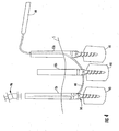
- the surgeon removes it from the anchoring member and places it into the next anchoring member (extender and screw), shown here as 12c attached to vertebra V3. The aforementioned procedure is then repeated inside anchoring member 12c. If an electromagnet is used, the electricity along the magnetic member is turned on and the strength of the magnetic field generated pulls the targeting member through the passageway 30 of the screw secured to V2 and toward the magnetic member located inside the screw secured to V3, see FIG. 2 . If a permanent magnet is used, the surgeons simply places the distal end inside the connector portion of the anchor.
- the pointed first end of the target member penetrates the tissue and creates a pathway through the tissues as it moves toward the magnetic material.
- This technique of threading through the screw does not require the surgeon to try to align multiple pedicle screws along the fixed path of the rod.
- the continuous magnetic attraction of the targeting member toward the pedicle screw reduces the possibility that the target member will be diverted by structures in the anatomical topography that may cause it to penetrate unintended areas.
- the present invention allows the surgeon to avoid a given anchor member. In such a circumstance the surgeon can insert the magnetic material into that extender connected to the anchor member that is to be avoided.
- the magnetic material maybe either a permanent magnet or electromagnet having the same polarity as that of the targeting member. This will repel the steering material of the target member from that target area.
- the magnetic member is used to pull the targeting member through the slot in the upper opening 43 of the pedicle screw and along the interior length of the extender until it reaches the proximal end protruding out of the incision.
- the surgeon can then grasp the targeting member and attached tethering means, see FIG. 3 .
- the tethering means located outside the patient is then used by the surgeon to gently pull the attached biocompatible member (rod) along the path formed through the tissue by the targeting member and through the connector portion of the pedicle(s) until the biocompatible member reaches the last vertebra, as shown in FIG. 4 .
- the user can disconnect the targeting member and releasably attach an injection means 96 thereto.
- the injecting means can be used into supply any suitable any flowable, biocompatible material inside the rod.
- a suitable biocompatible material includes at least one a hardening material that will cause the rod to become rigid.
- the rod might be filled prior to the introduction of a hardening material.
- the rod might contain ferroelectric material that allows the rod to remain flexible during insertion process until exposed to an electric current. This is particularly suitable if used in conjunction with the electromagnet embodiment previously described.
- the rod may then be exposed to electric current in the electromagnet by inserting the magnetic means into the extenders.
- the electric current causes the ferroelectric material to harden to make a substantially rigid rod.
- the contour of the rod corresponds to the natural curvature of the surrounding anatomy.
- the connector portion of the screw is constructed and arranged to receive a set screw 32 therein.
- the set screw is inserted into each of the extenders and threadably attached by the driving tool (not shown) positioned in the extender and inserted in tool opening in the screw.
- the interconnecting rod 44 is sandwiched between the upper portion of the head and the set screw. This acts to secure the rod onto the screws.
- the extenders are then removed from the connector portion of the screw and the exposures closed.
- any of the aforementioned embodiments of the system and techniques of the present invention can employ any type of known imaging system to determine and locate placement of any of the aforementioned structures in vivo.
- insertion of the anchor member into the bony structure can be pre-planned by CT scan, x-ray, or the imaging means known in the art.
- the present system may also include a feedback system having at least one detection element 120 (two are shown in FIG. 1 ) disposed outside and proximate the patient to determine the position of the targeting member and/or biocompatible member in real-time.
- the detection element is an audio receiver or pickup capable of audibly detecting when the targeting member and magnetic means connect or "click" together. This way, the surgeon can imagelessly determine that the targeting member has reached the magnetized portion of the anchoring member. This may be used in conjunction with a tactile sensation produced when the targeting member and magnetic means connect. This tactile sensation of the two elements meeting will be felt by the person holding the tethering means.
Landscapes
- Health & Medical Sciences (AREA)
- Orthopedic Medicine & Surgery (AREA)
- Life Sciences & Earth Sciences (AREA)
- Surgery (AREA)
- Neurology (AREA)
- Heart & Thoracic Surgery (AREA)
- Engineering & Computer Science (AREA)
- Biomedical Technology (AREA)
- Nuclear Medicine, Radiotherapy & Molecular Imaging (AREA)
- Medical Informatics (AREA)
- Molecular Biology (AREA)
- Animal Behavior & Ethology (AREA)
- General Health & Medical Sciences (AREA)
- Public Health (AREA)
- Veterinary Medicine (AREA)
- Surgical Instruments (AREA)
- Prostheses (AREA)
- Magnetic Treatment Devices (AREA)
Claims (9)
- Magnetisches Targeting-System (10), das für die Erleichterung einer Navigation zu einer in vivo befindlichen Zielfläche geeignet ist, wobei das System Folgendes aufweist:eine biokompatible Vorrichtung (44) und eine Mehrzahl von Ankerelementen (14), die ein proximales Ende (16) und ein distales Ende (18) aufweisen, wobei das distale Ende (18) dazu ausgestaltet und angeordnet ist, an einer in vivo befindlichen Zielfläche befestigt zu werden, wobei das proximale Ende (16) dazu ausgestaltet und angeordnet ist, ein magnetisches Material (62) aufzunehmen;ein magnetisches Material (62), das dazu ausgestaltet ist, in dem proximalen Ende (16) aufgenommen zu werden, eine hohle Verlängerung (12a, 12b, 12c), die an jedes Ankerelement (14) gekoppelt ist, wobei jede Verlängerung (12a, 12b, 12c) eine offene Oberseite aufweist und wobei mindestens eine erste Verlängerung (12a) einen sich längs erstreckenden Schlitz (63) aufweist, dadurch gekennzeichnet, dass:das Targeting-System (10) ferner ein Targeting-Element (20) mit einem ersten Ende (52) und einem zweiten Ende (54) aufweist, und wobei mindestens das erste Ende (52) ein Lenkungsmaterial (84), das durch ein magnetisches Feld beeinflusst wird, ein Haltemittel (42), das an dem zweiten Ende (54) des Targeting-Elements (20) und an der biokompatiblen Vorrichtung (44) befestigt ist, einschließt;wobei das magnetische Material (62) ein Anziehen oder Abstoßen des Lenkungsmaterials (84) in vivo bewirkt, so dass, wenn das magnetische Material (62) in dem proximalen Ende (16) des Ankerelements (14) aufgenommen ist, das magnetisch beeinflusste proximale Ende (16) des Ankerelements (14) mit dem ersten Ende (52) des Targeting-Elements (20) zusammenwirkt, so dass die verbundene biokompatible Vorrichtung (44) relativ zur Zielfläche positionierbar ist; und wobei das Targeting-Element (20) und die Verlängerungen (12a, 12b, 12c) so bemessen sind, dass das Targeting-Element (20) in die hohle Verlängerung (12a, 12b, 12c) durch die offene Oberseite verlaufen kann, und bei mindestens der ersten Verlängerung (12a) das Targeting-Element (20) aus der Verlängerung (12a) durch den sich längs erstreckenden Schlitz (63) austreten kann.
- Magnetisches Targeting-System nach Anspruch 1, wobei das System einen Echtzeit-Rückkopplungsmechanismus einschließt, um die Lage in vivo der biokompatiblen Vorrichtung (44) zu überprüfen.
- Magnetisches Targeting-System nach Anspruch 2, wobei der Echtzeit-Rückkopplungsmechanismus eine fühlbare Rückkopplung einschließt, um die Lage in vivo der biokompatiblen Vorrichtung (44) zu überprüfen.
- Magnetisches Targeting-System nach Anspruch 1, wobei das magnetische Material (62) ein Elektromagnet ist.
- Magnetisches Targeting-System nach Anspruch 1, wobei das magnetische Material (62) ein Dauermagnet ist.
- Magnetisches Targeting-System nach Anspruch 1, wobei die biokompatible Vorrichtung (44) ein Implantat oder ein chirurgisches Instrument ist.
- Magnetisches Targeting-System nach Anspruch 1, wobei die biokompatible Vorrichtung (44) aus einem Material gebildet ist, das aus der Gruppe bestehend aus einem starren, halbstarren oder flexiblen Material ausgewählt ist.
- Magnetisches Targeting-System nach Anspruch 1, wobei das Ankerelement (14) ein Befestigungsmittel zum Befestigen an einer knöchernen Struktur ist und die biokompatible Vorrichtung (44) ein Zwischenverbindungsmittel ist.
- Magnetisches Targeting-System nach Anspruch 1, wobei das Targeting-Element (20) aus einem Material gebildet ist, das aus der Gruppe bestehend aus starren, halbstarren oder flexiblen Materialien ausgewählt ist.
Applications Claiming Priority (1)
| Application Number | Priority Date | Filing Date | Title |
|---|---|---|---|
| PCT/US2008/054544 WO2009105104A1 (en) | 2008-02-21 | 2008-02-21 | Magnetic targeting system and method of using the same |
Publications (3)
| Publication Number | Publication Date |
|---|---|
| EP2249731A1 EP2249731A1 (de) | 2010-11-17 |
| EP2249731A4 EP2249731A4 (de) | 2012-10-31 |
| EP2249731B1 true EP2249731B1 (de) | 2017-08-30 |
Family
ID=40985820
Family Applications (1)
| Application Number | Title | Priority Date | Filing Date |
|---|---|---|---|
| EP08730366.5A Active EP2249731B1 (de) | 2008-02-21 | 2008-02-21 | Chirurgisches magnetisches target-system |
Country Status (9)
| Country | Link |
|---|---|
| EP (1) | EP2249731B1 (de) |
| JP (1) | JP5403763B2 (de) |
| KR (1) | KR101472847B1 (de) |
| CN (1) | CN101969870B (de) |
| AU (1) | AU2008350872B2 (de) |
| CA (1) | CA2716094A1 (de) |
| MX (1) | MX342779B (de) |
| NZ (1) | NZ587467A (de) |
| WO (1) | WO2009105104A1 (de) |
Families Citing this family (10)
| Publication number | Priority date | Publication date | Assignee | Title |
|---|---|---|---|---|
| US8333771B2 (en) | 2006-08-04 | 2012-12-18 | Magrod, Llc | System for pushing and pulling surgical implants into position in vivo via a tether |
| US8092458B2 (en) | 2006-08-04 | 2012-01-10 | Magrod, Llc | Magnetic targeting system and method of using the same |
| US8092461B2 (en) | 2006-08-04 | 2012-01-10 | Magrod, Llc | Method and apparatus for facilitating navigation of an implant |
| US7976546B2 (en) | 2006-08-04 | 2011-07-12 | Magrod, Llc | Magnetic targeting system for facilitating navigation |
| US9339309B1 (en) | 2012-10-11 | 2016-05-17 | Nuvasive, Inc. | Systems and methods for inserting cross-connectors |
| DE102015101650B4 (de) * | 2015-02-05 | 2018-05-03 | Aesculap Ag | Erfassungs- und Anzeigevorrichtung zum Erfassen und Anzeigen der Anwesenheit oder Abwesenheit eines Stabilisierungsstabes in dem Tulpenkopf einer Pedikelschraube, und spinales Stabilisierungssystem mit einer solchen Erfassungs- und Anzeigevorrichtung |
| US10606271B2 (en) | 2017-07-17 | 2020-03-31 | The Boeing Company | Magnetic navigation and positioning system |
| US11090131B2 (en) * | 2018-04-19 | 2021-08-17 | Medtronic Xomed, Inc. | System and method for tracking a subject |
| US20200022731A1 (en) * | 2018-07-20 | 2020-01-23 | Fellowship Of Orthopaedic Researchers, Inc. | Device for Realignment, Stabilization, and Prevention of Progression of Abnormal Spine Curvature |
| US11517352B1 (en) | 2021-06-22 | 2022-12-06 | Gomboc, LLC | Device and treatment of abnormal spine curvature |
Family Cites Families (12)
| Publication number | Priority date | Publication date | Assignee | Title |
|---|---|---|---|---|
| US6530929B1 (en) | 1999-10-20 | 2003-03-11 | Sdgi Holdings, Inc. | Instruments for stabilization of bony structures |
| US8956407B2 (en) * | 2000-09-20 | 2015-02-17 | Mvrx, Inc. | Methods for reshaping a heart valve annulus using a tensioning implant |
| US20030065373A1 (en) * | 2001-10-02 | 2003-04-03 | Lovett Eric G. | Medical device having rheometric materials and method therefor |
| JP4759266B2 (ja) * | 2002-10-03 | 2011-08-31 | ヴァージニア テック インテレクチュアル プロパティーズ,インコーポレイテッド | 磁気標的装置 |
| GB0315479D0 (en) * | 2003-07-02 | 2003-08-06 | Paz Adrian | Virtual ports devices |
| US20050203513A1 (en) * | 2003-09-24 | 2005-09-15 | Tae-Ahn Jahng | Spinal stabilization device |
| CN2681693Y (zh) * | 2004-03-06 | 2005-03-02 | 孙德修 | 带锁髓内钉远端钉孔瞄准自动指示仪 |
| US20070239159A1 (en) | 2005-07-22 | 2007-10-11 | Vertiflex, Inc. | Systems and methods for stabilization of bone structures |
| JP4505360B2 (ja) * | 2005-03-23 | 2010-07-21 | オリンパスメディカルシステムズ株式会社 | 磁性体留置具の探知及び把持装置 |
| US7967820B2 (en) * | 2006-02-07 | 2011-06-28 | P Tech, Llc. | Methods and devices for trauma welding |
| US7520879B2 (en) | 2006-02-07 | 2009-04-21 | Warsaw Orthopedic, Inc. | Surgical instruments and techniques for percutaneous placement of spinal stabilization elements |
| US20070270815A1 (en) * | 2006-04-20 | 2007-11-22 | Chris Johnson | Bone anchors with end-loading receivers for elongated connecting elements in spinal surgical procedures |
-
2008
- 2008-02-21 JP JP2010547604A patent/JP5403763B2/ja not_active Expired - Fee Related
- 2008-02-21 KR KR1020107020596A patent/KR101472847B1/ko not_active Expired - Fee Related
- 2008-02-21 MX MX2010009218A patent/MX342779B/es active IP Right Grant
- 2008-02-21 CN CN200880127333.3A patent/CN101969870B/zh not_active Expired - Fee Related
- 2008-02-21 CA CA2716094A patent/CA2716094A1/en not_active Abandoned
- 2008-02-21 AU AU2008350872A patent/AU2008350872B2/en active Active
- 2008-02-21 WO PCT/US2008/054544 patent/WO2009105104A1/en not_active Ceased
- 2008-02-21 EP EP08730366.5A patent/EP2249731B1/de active Active
- 2008-02-21 NZ NZ587467A patent/NZ587467A/xx not_active IP Right Cessation
Also Published As
| Publication number | Publication date |
|---|---|
| JP5403763B2 (ja) | 2014-01-29 |
| MX342779B (es) | 2016-10-12 |
| CN101969870A (zh) | 2011-02-09 |
| AU2008350872A1 (en) | 2009-08-27 |
| AU2008350872B2 (en) | 2014-09-25 |
| CA2716094A1 (en) | 2009-08-27 |
| CN101969870B (zh) | 2015-06-17 |
| WO2009105104A1 (en) | 2009-08-27 |
| KR101472847B1 (ko) | 2014-12-16 |
| EP2249731A4 (de) | 2012-10-31 |
| JP2011512891A (ja) | 2011-04-28 |
| EP2249731A1 (de) | 2010-11-17 |
| MX2010009218A (es) | 2011-04-11 |
| KR20110000630A (ko) | 2011-01-04 |
| NZ587467A (en) | 2013-05-31 |
Similar Documents
| Publication | Publication Date | Title |
|---|---|---|
| US8092460B2 (en) | Magnetic targeting system and method of using the same | |
| USRE46096E1 (en) | Magnetic targeting system and method of using the same | |
| US8092461B2 (en) | Method and apparatus for facilitating navigation of an implant | |
| EP2249731B1 (de) | Chirurgisches magnetisches target-system | |
| US8333771B2 (en) | System for pushing and pulling surgical implants into position in vivo via a tether | |
| JP5524966B2 (ja) | 手術用器具の電子式案内 | |
| US6993374B2 (en) | Instrumentation and method for mounting a surgical navigation reference device to a patient | |
| US9283019B2 (en) | Flexible guide wire | |
| EP3998972B1 (de) | Wirbelsäulenimplantatsystem | |
| KR20200023652A (ko) | 척추 임플란트 시스템 및 방법 | |
| CN110430831A (zh) | 脊柱植入系统和方法 | |
| US9339309B1 (en) | Systems and methods for inserting cross-connectors |
Legal Events
| Date | Code | Title | Description |
|---|---|---|---|
| PUAI | Public reference made under article 153(3) epc to a published international application that has entered the european phase |
Free format text: ORIGINAL CODE: 0009012 |
|
| 17P | Request for examination filed |
Effective date: 20100921 |
|
| AK | Designated contracting states |
Kind code of ref document: A1 Designated state(s): AT BE BG CH CY CZ DE DK EE ES FI FR GB GR HR HU IE IS IT LI LT LU LV MC MT NL NO PL PT RO SE SI SK TR |
|
| AX | Request for extension of the european patent |
Extension state: AL BA MK RS |
|
| RAP1 | Party data changed (applicant data changed or rights of an application transferred) |
Owner name: MAGROD, LLC |
|
| DAX | Request for extension of the european patent (deleted) | ||
| A4 | Supplementary search report drawn up and despatched |
Effective date: 20120928 |
|
| RIC1 | Information provided on ipc code assigned before grant |
Ipc: A61B 17/88 20060101AFI20120924BHEP Ipc: A61B 17/70 20060101ALI20120924BHEP Ipc: A61B 17/16 20060101ALI20120924BHEP |
|
| RAP1 | Party data changed (applicant data changed or rights of an application transferred) |
Owner name: NUVASIVE, INC. |
|
| GRAP | Despatch of communication of intention to grant a patent |
Free format text: ORIGINAL CODE: EPIDOSNIGR1 |
|
| INTG | Intention to grant announced |
Effective date: 20161128 |
|
| GRAS | Grant fee paid |
Free format text: ORIGINAL CODE: EPIDOSNIGR3 |
|
| GRAA | (expected) grant |
Free format text: ORIGINAL CODE: 0009210 |
|
| AK | Designated contracting states |
Kind code of ref document: B1 Designated state(s): AT BE BG CH CY CZ DE DK EE ES FI FR GB GR HR HU IE IS IT LI LT LU LV MC MT NL NO PL PT RO SE SI SK TR |
|
| REG | Reference to a national code |
Ref country code: GB Ref legal event code: FG4D |
|
| REG | Reference to a national code |
Ref country code: CH Ref legal event code: EP |
|
| REG | Reference to a national code |
Ref country code: AT Ref legal event code: REF Ref document number: 922782 Country of ref document: AT Kind code of ref document: T Effective date: 20170915 |
|
| REG | Reference to a national code |
Ref country code: IE Ref legal event code: FG4D |
|
| REG | Reference to a national code |
Ref country code: DE Ref legal event code: R096 Ref document number: 602008051889 Country of ref document: DE |
|
| REG | Reference to a national code |
Ref country code: CH Ref legal event code: NV Representative=s name: KIRKER AND CIE S.A., CH |
|
| REG | Reference to a national code |
Ref country code: NL Ref legal event code: MP Effective date: 20170830 |
|
| REG | Reference to a national code |
Ref country code: LT Ref legal event code: MG4D |
|
| REG | Reference to a national code |
Ref country code: AT Ref legal event code: MK05 Ref document number: 922782 Country of ref document: AT Kind code of ref document: T Effective date: 20170830 |
|
| PG25 | Lapsed in a contracting state [announced via postgrant information from national office to epo] |
Ref country code: SE Free format text: LAPSE BECAUSE OF FAILURE TO SUBMIT A TRANSLATION OF THE DESCRIPTION OR TO PAY THE FEE WITHIN THE PRESCRIBED TIME-LIMIT Effective date: 20170830 Ref country code: NO Free format text: LAPSE BECAUSE OF FAILURE TO SUBMIT A TRANSLATION OF THE DESCRIPTION OR TO PAY THE FEE WITHIN THE PRESCRIBED TIME-LIMIT Effective date: 20171130 Ref country code: AT Free format text: LAPSE BECAUSE OF FAILURE TO SUBMIT A TRANSLATION OF THE DESCRIPTION OR TO PAY THE FEE WITHIN THE PRESCRIBED TIME-LIMIT Effective date: 20170830 Ref country code: LT Free format text: LAPSE BECAUSE OF FAILURE TO SUBMIT A TRANSLATION OF THE DESCRIPTION OR TO PAY THE FEE WITHIN THE PRESCRIBED TIME-LIMIT Effective date: 20170830 Ref country code: HR Free format text: LAPSE BECAUSE OF FAILURE TO SUBMIT A TRANSLATION OF THE DESCRIPTION OR TO PAY THE FEE WITHIN THE PRESCRIBED TIME-LIMIT Effective date: 20170830 Ref country code: FI Free format text: LAPSE BECAUSE OF FAILURE TO SUBMIT A TRANSLATION OF THE DESCRIPTION OR TO PAY THE FEE WITHIN THE PRESCRIBED TIME-LIMIT Effective date: 20170830 |
|
| PG25 | Lapsed in a contracting state [announced via postgrant information from national office to epo] |
Ref country code: IS Free format text: LAPSE BECAUSE OF FAILURE TO SUBMIT A TRANSLATION OF THE DESCRIPTION OR TO PAY THE FEE WITHIN THE PRESCRIBED TIME-LIMIT Effective date: 20171230 Ref country code: ES Free format text: LAPSE BECAUSE OF FAILURE TO SUBMIT A TRANSLATION OF THE DESCRIPTION OR TO PAY THE FEE WITHIN THE PRESCRIBED TIME-LIMIT Effective date: 20170830 Ref country code: BG Free format text: LAPSE BECAUSE OF FAILURE TO SUBMIT A TRANSLATION OF THE DESCRIPTION OR TO PAY THE FEE WITHIN THE PRESCRIBED TIME-LIMIT Effective date: 20171130 Ref country code: LV Free format text: LAPSE BECAUSE OF FAILURE TO SUBMIT A TRANSLATION OF THE DESCRIPTION OR TO PAY THE FEE WITHIN THE PRESCRIBED TIME-LIMIT Effective date: 20170830 Ref country code: GR Free format text: LAPSE BECAUSE OF FAILURE TO SUBMIT A TRANSLATION OF THE DESCRIPTION OR TO PAY THE FEE WITHIN THE PRESCRIBED TIME-LIMIT Effective date: 20171201 |
|
| PG25 | Lapsed in a contracting state [announced via postgrant information from national office to epo] |
Ref country code: NL Free format text: LAPSE BECAUSE OF FAILURE TO SUBMIT A TRANSLATION OF THE DESCRIPTION OR TO PAY THE FEE WITHIN THE PRESCRIBED TIME-LIMIT Effective date: 20170830 |
|
| PG25 | Lapsed in a contracting state [announced via postgrant information from national office to epo] |
Ref country code: CZ Free format text: LAPSE BECAUSE OF FAILURE TO SUBMIT A TRANSLATION OF THE DESCRIPTION OR TO PAY THE FEE WITHIN THE PRESCRIBED TIME-LIMIT Effective date: 20170830 Ref country code: RO Free format text: LAPSE BECAUSE OF FAILURE TO SUBMIT A TRANSLATION OF THE DESCRIPTION OR TO PAY THE FEE WITHIN THE PRESCRIBED TIME-LIMIT Effective date: 20170830 Ref country code: DK Free format text: LAPSE BECAUSE OF FAILURE TO SUBMIT A TRANSLATION OF THE DESCRIPTION OR TO PAY THE FEE WITHIN THE PRESCRIBED TIME-LIMIT Effective date: 20170830 Ref country code: PL Free format text: LAPSE BECAUSE OF FAILURE TO SUBMIT A TRANSLATION OF THE DESCRIPTION OR TO PAY THE FEE WITHIN THE PRESCRIBED TIME-LIMIT Effective date: 20170830 |
|
| PG25 | Lapsed in a contracting state [announced via postgrant information from national office to epo] |
Ref country code: IT Free format text: LAPSE BECAUSE OF FAILURE TO SUBMIT A TRANSLATION OF THE DESCRIPTION OR TO PAY THE FEE WITHIN THE PRESCRIBED TIME-LIMIT Effective date: 20170830 Ref country code: SK Free format text: LAPSE BECAUSE OF FAILURE TO SUBMIT A TRANSLATION OF THE DESCRIPTION OR TO PAY THE FEE WITHIN THE PRESCRIBED TIME-LIMIT Effective date: 20170830 Ref country code: EE Free format text: LAPSE BECAUSE OF FAILURE TO SUBMIT A TRANSLATION OF THE DESCRIPTION OR TO PAY THE FEE WITHIN THE PRESCRIBED TIME-LIMIT Effective date: 20170830 |
|
| REG | Reference to a national code |
Ref country code: DE Ref legal event code: R097 Ref document number: 602008051889 Country of ref document: DE |
|
| PLBE | No opposition filed within time limit |
Free format text: ORIGINAL CODE: 0009261 |
|
| STAA | Information on the status of an ep patent application or granted ep patent |
Free format text: STATUS: NO OPPOSITION FILED WITHIN TIME LIMIT |
|
| 26N | No opposition filed |
Effective date: 20180531 |
|
| PG25 | Lapsed in a contracting state [announced via postgrant information from national office to epo] |
Ref country code: SI Free format text: LAPSE BECAUSE OF FAILURE TO SUBMIT A TRANSLATION OF THE DESCRIPTION OR TO PAY THE FEE WITHIN THE PRESCRIBED TIME-LIMIT Effective date: 20170830 |
|
| PG25 | Lapsed in a contracting state [announced via postgrant information from national office to epo] |
Ref country code: MC Free format text: LAPSE BECAUSE OF FAILURE TO SUBMIT A TRANSLATION OF THE DESCRIPTION OR TO PAY THE FEE WITHIN THE PRESCRIBED TIME-LIMIT Effective date: 20170830 |
|
| REG | Reference to a national code |
Ref country code: IE Ref legal event code: MM4A |
|
| REG | Reference to a national code |
Ref country code: BE Ref legal event code: MM Effective date: 20180228 |
|
| PG25 | Lapsed in a contracting state [announced via postgrant information from national office to epo] |
Ref country code: LU Free format text: LAPSE BECAUSE OF NON-PAYMENT OF DUE FEES Effective date: 20180221 |
|
| REG | Reference to a national code |
Ref country code: FR Ref legal event code: ST Effective date: 20181031 |
|
| PG25 | Lapsed in a contracting state [announced via postgrant information from national office to epo] |
Ref country code: IE Free format text: LAPSE BECAUSE OF NON-PAYMENT OF DUE FEES Effective date: 20180221 |
|
| PG25 | Lapsed in a contracting state [announced via postgrant information from national office to epo] |
Ref country code: FR Free format text: LAPSE BECAUSE OF NON-PAYMENT OF DUE FEES Effective date: 20180228 Ref country code: BE Free format text: LAPSE BECAUSE OF NON-PAYMENT OF DUE FEES Effective date: 20180228 |
|
| PG25 | Lapsed in a contracting state [announced via postgrant information from national office to epo] |
Ref country code: MT Free format text: LAPSE BECAUSE OF NON-PAYMENT OF DUE FEES Effective date: 20180221 |
|
| PG25 | Lapsed in a contracting state [announced via postgrant information from national office to epo] |
Ref country code: TR Free format text: LAPSE BECAUSE OF FAILURE TO SUBMIT A TRANSLATION OF THE DESCRIPTION OR TO PAY THE FEE WITHIN THE PRESCRIBED TIME-LIMIT Effective date: 20170830 |
|
| PG25 | Lapsed in a contracting state [announced via postgrant information from national office to epo] |
Ref country code: HU Free format text: LAPSE BECAUSE OF FAILURE TO SUBMIT A TRANSLATION OF THE DESCRIPTION OR TO PAY THE FEE WITHIN THE PRESCRIBED TIME-LIMIT; INVALID AB INITIO Effective date: 20080221 Ref country code: PT Free format text: LAPSE BECAUSE OF FAILURE TO SUBMIT A TRANSLATION OF THE DESCRIPTION OR TO PAY THE FEE WITHIN THE PRESCRIBED TIME-LIMIT Effective date: 20170830 |
|
| PG25 | Lapsed in a contracting state [announced via postgrant information from national office to epo] |
Ref country code: CY Free format text: LAPSE BECAUSE OF FAILURE TO SUBMIT A TRANSLATION OF THE DESCRIPTION OR TO PAY THE FEE WITHIN THE PRESCRIBED TIME-LIMIT Effective date: 20170830 |
|
| PGFP | Annual fee paid to national office [announced via postgrant information from national office to epo] |
Ref country code: CH Payment date: 20220120 Year of fee payment: 15 |
|
| REG | Reference to a national code |
Ref country code: CH Ref legal event code: PL |
|
| PG25 | Lapsed in a contracting state [announced via postgrant information from national office to epo] |
Ref country code: LI Free format text: LAPSE BECAUSE OF NON-PAYMENT OF DUE FEES Effective date: 20230228 Ref country code: CH Free format text: LAPSE BECAUSE OF NON-PAYMENT OF DUE FEES Effective date: 20230228 |
|
| PGFP | Annual fee paid to national office [announced via postgrant information from national office to epo] |
Ref country code: GB Payment date: 20260106 Year of fee payment: 19 |
|
| PGFP | Annual fee paid to national office [announced via postgrant information from national office to epo] |
Ref country code: DE Payment date: 20251230 Year of fee payment: 19 |