EP2249943B1 - Filtre à soufflets multiples, à rendement accru - Google Patents
Filtre à soufflets multiples, à rendement accru Download PDFInfo
- Publication number
- EP2249943B1 EP2249943B1 EP09715396.9A EP09715396A EP2249943B1 EP 2249943 B1 EP2249943 B1 EP 2249943B1 EP 09715396 A EP09715396 A EP 09715396A EP 2249943 B1 EP2249943 B1 EP 2249943B1
- Authority
- EP
- European Patent Office
- Prior art keywords
- filter
- bellows
- folds
- air
- filter bellows
- Prior art date
- Legal status (The legal status is an assumption and is not a legal conclusion. Google has not performed a legal analysis and makes no representation as to the accuracy of the status listed.)
- Active
Links
Images

Classifications
-
- B—PERFORMING OPERATIONS; TRANSPORTING
- B01—PHYSICAL OR CHEMICAL PROCESSES OR APPARATUS IN GENERAL
- B01D—SEPARATION
- B01D46/00—Filters or filtering processes specially modified for separating dispersed particles from gases or vapours
- B01D46/52—Particle separators, e.g. dust precipitators, using filters embodying folded corrugated or wound sheet material
- B01D46/528—Particle separators, e.g. dust precipitators, using filters embodying folded corrugated or wound sheet material using wound sheets
-
- B—PERFORMING OPERATIONS; TRANSPORTING
- B01—PHYSICAL OR CHEMICAL PROCESSES OR APPARATUS IN GENERAL
- B01D—SEPARATION
- B01D46/00—Filters or filtering processes specially modified for separating dispersed particles from gases or vapours
- B01D46/24—Particle separators, e.g. dust precipitators, using rigid hollow filter bodies
- B01D46/2403—Particle separators, e.g. dust precipitators, using rigid hollow filter bodies characterised by the physical shape or structure of the filtering element
- B01D46/2411—Filter cartridges
-
- B—PERFORMING OPERATIONS; TRANSPORTING
- B01—PHYSICAL OR CHEMICAL PROCESSES OR APPARATUS IN GENERAL
- B01D—SEPARATION
- B01D46/00—Filters or filtering processes specially modified for separating dispersed particles from gases or vapours
- B01D46/52—Particle separators, e.g. dust precipitators, using filters embodying folded corrugated or wound sheet material
- B01D46/521—Particle separators, e.g. dust precipitators, using filters embodying folded corrugated or wound sheet material using folded, pleated material
- B01D46/522—Particle separators, e.g. dust precipitators, using filters embodying folded corrugated or wound sheet material using folded, pleated material with specific folds, e.g. having different lengths
-
- B—PERFORMING OPERATIONS; TRANSPORTING
- B01—PHYSICAL OR CHEMICAL PROCESSES OR APPARATUS IN GENERAL
- B01D—SEPARATION
- B01D46/00—Filters or filtering processes specially modified for separating dispersed particles from gases or vapours
- B01D46/56—Filters or filtering processes specially modified for separating dispersed particles from gases or vapours with multiple filtering elements, characterised by their mutual disposition
- B01D46/58—Filters or filtering processes specially modified for separating dispersed particles from gases or vapours with multiple filtering elements, characterised by their mutual disposition connected in parallel
- B01D46/60—Filters or filtering processes specially modified for separating dispersed particles from gases or vapours with multiple filtering elements, characterised by their mutual disposition connected in parallel arranged concentrically or coaxially
-
- F—MECHANICAL ENGINEERING; LIGHTING; HEATING; WEAPONS; BLASTING
- F02—COMBUSTION ENGINES; HOT-GAS OR COMBUSTION-PRODUCT ENGINE PLANTS
- F02M—SUPPLYING COMBUSTION ENGINES IN GENERAL WITH COMBUSTIBLE MIXTURES OR CONSTITUENTS THEREOF
- F02M35/00—Combustion-air cleaners, air intakes, intake silencers, or induction systems specially adapted for, or arranged on, internal-combustion engines
- F02M35/02—Air cleaners
- F02M35/024—Air cleaners using filters, e.g. moistened
Definitions
- the invention relates to a filter element or an air filter, and in particular to a filter element or an air filter in the embodiment of a Mehrfachbalgfilters with an increased efficiency for use in internal combustion engines.
- the combustion air required for internal combustion engines is usually cleaned prior to feeding into the combustion chamber in order to increase the performance and the service life of the internal combustion engine.
- an air filter arrangement is used for the purification of the combustion air usually. This is particularly important for internal combustion engines that operate in an environment that is exposed to a special pollution load of the ambient air, such as in the field of construction or agriculture. Particularly in the field of construction or in agriculture occurs sometimes very high levels of dust, which makes it necessary to clean the combustion air. Due to the fact that the spectrum of the dust particle size is not previously known as a rule, an air filter assembly must be designed so that all particle sizes that can affect the operation of the internal combustion engine in any way, can be reliably filtered out to supply a sufficiently clean combustion air to allow the internal combustion engine.
- An air filter which is integrated in the intake tract of an internal combustion engine in order to subject the combustion air to be supplied to the cylinders of the internal combustion engine to filtration.
- the air filter is essentially in three parts constructed and includes in a filter housing a filter element which is designed as a replaceable filter cartridge, which is flowed through axially by the combustion air and can be inserted radially via a closable lid in the filter housing.
- the filter cartridge is preceded by a cyclone pre-separator, which serves for the separation of coarse dirt particles.
- Downstream of the filter cartridge is a secondary or fine filter element, which is also radially inserted with the lid open in the filter housing.
- the cyclone pre-separator, the filter cartridge and the fine filter element are axially behind one another and are flowed through in the axial direction without deflection of the combustion air to be cleaned.
- a bellows filter consist of a star-shaped folded filter element whose filter folds extend in the radial direction, wherein the end edges of the filter folds extend substantially in an axial direction.
- a filter bellows is known, for example WO 2008/067030 in that the filter element consists of a folded filter bellows, wherein the end edges of the filter pleats extend in an axial direction which corresponds to a flow direction, while the filter pleats extend in a direction transverse thereto.
- This bellows consists of a multi-bellows, which provides an increased filter area on a limited axial section or a section in the direction of flow, in order to increase the filter capacity in this way.
- the present invention has the object to provide a filter element or an air filter for internal combustion engines, which has an improved efficiency and allows an optimized flow.
- a filter element for an air filter of an internal combustion engine wherein the filter element has a first filter bellows with filter folds extending substantially in an axial extension direction of the filter element and a first fold depth extending substantially in a plane extending orthogonally in the radial extension direction and a second filter bellows having filter folds extending substantially in an axial extension direction of the filter element and a second fold depth extending substantially in a plane extending orthogonally in the radial extension direction, the second filter bellows being arranged radially inward to the first filter bellows, wherein a depth of the second filter folds is deeper than a depth of the corresponding first filter folds.
- the first and second filter bellows in a plane of the radial expansion direction, have a first bent portion and a second bent portion having a first substantially straight portion therebetween and a second substantially straight portion such that the first and second bent portions and the first and second substantially straight sections represent a closed oval peripheral contour.
- the filter element can be made narrow so that it has a long axis and a short axis, for example, wherein the filter element along the long axis can be introduced into the air filter housing.
- the actual lid opening for closing the air filter housing after a change of the air filter can be made relatively small. This is especially important against the background of the seal geometry.
- the substantially straight portions may also have some curvature, and in this embodiment also embodiments are read in which the bent portions have a substantially higher curvature than the substantially straight portions, regardless of whether substantially Straight sections are actually straight or provided with a certain curvature.
- the first straight section having the second straight section is connected to a first seal member such that a clean gas side and a raw gas side of the second filter bellows are mis-sealed from each other.
- the first filter bellows and the second filter bellows are connected to each other at a second axial end with a second sealing element such that in each case the clean gas sides and the raw gas sides of the first filter bellows or of the second filter bellows are separated from each other in a false air-tight manner.
- first filter bellows and the second filter bellows can be sealingly connected to each other.
- the second sealing element can also be designed as an edge protection, when the second sealing element extends to the outer contour of the second axial end of the first filter bellows.
- a filter element in the form of a Mehrfachbalgfilters be provided, which has an increased efficiency and at the same time allows an optimized flow through the combustion air to be filtered.
- the second filter bellows is arranged radially inwardly to the first filter bellows, in the case of a circular or oval configuration of the filter bellows, for example in the form of a star filter bellows, the circumference of the first, outer filter bellows is generally greater than the circumference of the second, inner filter bellows.
- the filter bellows Due to the different circumferences of the filter bellows, it is possible to arrange a larger number of filter folds along the circumference in the first filter bellows in comparison to the second filter bellows. Thus, in general, the first filter bellows will have a larger number of filter pleats than the second filter bellows. In order to approximate the filter surface loading of the two filter bellows to one another, the depth of the filter folds of the second, inner filter bellows is made deeper than the depth of the corresponding filter folds of the first, outer filter bellows. Due to this different configuration, the filter area of the inner, second filter bellows can be increased in order to achieve this compensate for the larger circumference of the first filter bellows. Thus, it can be achieved that the first filter bellows and the second filter bellows are flowed through more uniformly, in order to increase the efficiency of the filter element in this way.
- a filter element in the form of a Mehrfachbalgfilters may of course have more than two radially inrapbetween Filterbälge, in particular with a larger number of radially interposed Filterbälge by increasing depth of fold with farther inside Filterbälgen a more uniform flow through the filter element can be achieved.
- the pleat depth may vary along the circumference of a filter element, such as to follow an outer geometry constraint so that there may be areas along the perimeter which have a higher pleat depth than other areas along the same circumference. In such cases, it may well happen that the second, inner bellows filter folds, which have a smaller depth than filter pleats of the first filter bellows, if they are not opposite and therefore do not correspond.
- the depth of the second filter pleats is a factor of 1.1 to 2.5, in particular by a factor of substantially 1.2 to 1.9, lower than the depth of the corresponding first filter pleats.
- the filter folds of the second filter bellows are inclined at least in sections relative to the filter folds of the first filter bellows in an axial expansion direction.
- the filter pleats By an inclination of the filter pleats they can be made longer by a certain diagonal component, so that the effective filter area of the second filter bellows relative to the first filter bellows relatively increased not only by an increased depth of wrinkles, but also brings due to an inclination increased pleat length with it. In this way, also the effective filter area of the second bellows relative to the first bellows can be increased.
- the discharge channel in the region of the outlet orifice can have a large cross-sectional area, while the discharge channel has a smaller cross-sectional area in the lower regions.
- the outflow channel located on the other side of the corresponding filter bellows can be made narrow, while in regions where the inflow passage is narrow, the outflow passage can be made wide. In this way, the radial extent of the Filterfaltenbalgan extract ever can be made more compact.
- an inclination of the filter pleats of the second filter bellows to the axial extension direction is greater than an inclination of the filter pleats of the first filter bellows to the axial extension direction.
- first filter bellows can also extend substantially parallel to the axial extension direction, thus having an inclination of substantially zero degrees.
- first filter bellows as well as the second filter bellows may have an inclination, but the inclination of the second filter bellows is greater than that of the first filter bellows so as to be able to provide both an increased surface area on the second filter bellows and a conical shape due to the inclination Design of the inflow and outflow to allow.
- the first filter bellows is provided at a first axial end with a respect to an outer edge of the first filter bellows form accommodateden shell.
- the shape-retaining shell may additionally be provided with a seal configuration, which may serve for the sealing introduction of the filter element in an air filter housing.
- the shape-preserving shell may comprise gripping elements by means of which the filter element can be introduced in a manner safe to handle into an air filter housing or can be removed therefrom. This is particularly important when the insertion or removal of the filter element is performed by less trained personnel, who is often unaware of the sensitivity and operation of a filter element.
- the shape-preserving shell may also have an arrangement which allows an improved flow of air to be filtered on the Anströmkanäle, for example in the form of air baffles or other flow-optimized geometry.
- the substantially first and second straight sections converge in the plane of the radial extension direction.
- the inner bellows corresponds to its shape with the shape of the outer bellows.
- a flow-optimized geometry and a flow-optimized inflow channel can be provided which results from the intermediate space between the first filter bellows and the second filter bellows, and which can also represent a closed oval peripheral contour.
- the essentially straight sections lying opposite one another can thus be connected to one another by a sealing bead, so that an inlet or outlet channel is formed on the second axial end lying opposite the first axial end. which tapers in the direction of the first axial end.
- a sealing bead which tapers in the direction of the first axial end.
- the first sealing element in a plane of the radial expansion direction extends only partially over the depth of the second filter pleats of the second filter bellows.
- the sealing element can essentially take over only the seal of the two substantially straight sections, which lie in the oval shape, while be provided in the filter pleats for separating the raw gas from the clean gas side a bead bonding, which is adjacent, for example, to the first sealing element.
- the second sealing element in a plane of the radial expansion direction extends only partially over the depth of the first filter pleats and the second filter pleats.
- the second sealing element can be made relatively narrow and in a bonding of the first filter folds or the second filter folds by a bead bonding the corresponding opposite sides of the filter pleats can be left open, so that an increase in the effective arrival or downstream surfaces result in a supply or discharge channel.
- an edge or impact protection may be provided on the outer contour of the second axial end of the first filter bellows, which may for example be designed as a shape-preserving shell, but may also be made of the same material as the second sealing element, which may be particularly important from an optimization point of view of a production process.
- the sealing element comprises a polyurethane foam or other materials suitable for a gasket (e.g., other silicone or castables such as polyamide or polyurethane foams).
- a gasket e.g., other silicone or castables such as polyamide or polyurethane foams.
- Polyurethane foams are relatively easy to handle and bond quickly, but have the desired properties that are suitable for a sealing function, but also for an edge protection function.
- the polyurethane (PUR) foam-containing sealing elements can be both the first sealing element and the second sealing element, but also other sealing elements.
- the caterpillar bonding can also be carried out with polyurethane foam having sealing material.
- a clean gas side of the first filter bellows faces a clean gas side of the second filter bellows.
- the inflow side and thus the raw gas side have two inflow channels, namely an outer inflow channel, which is defined by the outer surface of the filter element, and a second coaxially extending inner inflow channel, which is defined by the raw gas side of the second filter element.
- an arrangement with more than two radially nested filter elements resulting in this way correspondingly more inflow and outflow.
- Such an embodiment with two inflow channels on the raw gas side and a discharge channel on a clean gas side in a filter element in a design with two filter bellows can thus enable optimized flow on the inflow side by an example cyclone arrangement, which is aligned with the corresponding inflow channels.
- Analog can be provided on the outflow channel side a corresponding arrangement of a security element.
- the sealing of the filter element with respect to the air filter housing at a greater distance to the pre-separator can be made, so that a burden of this seal assembly by the flow from the Reduce pre-separator.
- the outflow channel of the air filter housing can be designed with a smaller cross-sectional area than the inflow channel of the air filter housing, since the outflow channel is not constricted geometrically by the filtrate in contrast to the inflow passage over the lifetime.
- the first filter bellows has a first raw gas side and a first clean gas side
- the second filter bellows a second raw gas side and a second clean gas side
- the first filter bellows and the second filter bellows in such a manner on an end face of the first filter bellows and a front side of the second filter bellows are impermeably connected with one another such that either a first raw gas-side space corresponds to a second raw-gas-side space or a first clean-gas-side space corresponds to a second clean-gas-side space.
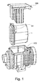
- FIG. 1 shows a schematic representation of an air filter housing 100 with a filter element to be used therein 1 and a closure or holding cover 199.
- the air filter housing 100 may include or receive a prefilter and a safety filter element next to the filter element 1, which is designed here as the main filter element.
- the filter element 1 is introduced in a direction orthogonal to the flow direction in the air filter housing. With help a corresponding geometry on the closure element 199, the introduced into the air filter housing 100 filter element 1 can be pressed, for example, sealingly against a corresponding sealing surface in the air filter housing 1. The application of force can take place in a substantially axial direction corresponding to the direction of flow.
- the filter element 1 has a seal configuration which requires a substantially radial application of force, so that by the closure element 199 is not necessarily a contact pressure in the axial direction must be.
- the closure element 199 may also have a corresponding sealing contact surface for the filter element 1.
- the closure element 199 expediently has a sealing configuration with which the air filter housing 100 can be sealingly closed when the filter element 1 is inserted.
- the filter element 1 can, as in FIG. 1 shown having a handle 94, with which the filter element can be introduced into both the air filter housing 100 and can be removed therefrom.
- Such handles 94 are suitably designed so that they can be found easily when no eye contact between an operator and the filter element 1 is present or the operator may also wearing protective gloves.
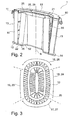
- FIG. 2 shows a schematic sectional view of a filter element according to an exemplary embodiment of the invention.
- the section through the filter element is designed in an axial extension direction A, along a longest extent in a radial expansion plane.
- the filter element 1 is provided with a first bellows 10 and a second bellows 20.
- the second bellows 20 lies radially inward relative to the first bellows 10.
- the first filter bellows 10 has filter pleats 15 which have a first pleat depth extending substantially in a plane orthogonal to the axial direction in the radial expansion direction.
- the second filter bellows 20 have filter folds 25 which extend in a plane extending essentially orthogonally to the axial expansion direction in the radial expansion direction.
- first filter bellows 10 and the second filter bellows 20 are folded in the form of a star filter.
- the second filter bellows 20 has a higher folding depth compared to the first filter bellows 10. In this way, the effective filter area of the inner second filter bellows 20 can be increased.
- the following table shows a selection of possible configurations that a filter device according to the invention may have.
- the first bellows 10 is provided at a first axial end 11 with a dimensionally stable cover 60.
- This dimensionally stable cover can be as in the FIG. 2 shown extend over the entire depth of wrinkles of the first bellows 10.
- this shape-preserving shell can also extend only over parts of the first fold depth of the bellows 10 and leave the folds uncovered, for example, at the radially inner region lying opposite to the folds of the second bellows 20 in a direction of flow. In the latter case, the effective inflow area increases in a channel which is formed by the first bellows 10 and the second bellows 20.
- the shape-preserving shell 60 may for example consist of a relatively hard plastic, as well as of a metal or other dimensionally stable material.
- the dimensionally stable shell 60 can be glued sealingly, for example by means of a polyurethane (PUR) foam. Furthermore, a sealing configuration can be arranged on the shape-preserving shell 60, with which the filter element can be sealed against an air filter housing, so that a raw gas side and a clean gas side of the filter element can be separated from each other in an air-tight manner.
- the provided Dichtungskonfguration can be both an axially sealing seal and a radially sealing seal.
- FIG. 2 embodiment shown here shows a circumferential seal groove into which a corresponding sealing geometry of an air filter housing or an air filter housing cover can intervene.
- the first filter bellows as well as the second filter bellows may have a curved first region 16, 26 and a curved second region 17, 27 and in each case first substantially straight region 18, 28 and a second substantially straight region 19, 29, such as later referring to FIG. 3 will be described.
- the substantially straight regions 28, 29 of the second bellows can be sealingly connected to each other with a sealing element 51 such that a clean gas side and a raw gas side are incorrectly separated from each other.
- the sealing element 51 may, for example, extend only partially over the filter folds 25 of the second filter bellows.
- the folds can then be adhesively bonded or closed on one side, so that a separation of raw gas side and clean gas side is achieved even with only partial overlap of the fold depth by the sealing element.
- the bond is then arranged on the side facing the sealing element.
- the sealing element 51 extends over the entire pleat depth of the filter pleats 25. In this case, an increased impact protection is made possible, in particular for the exposed corners of the filter pleats 25, but the effective inflow or outflow surface of an inflow or outflow channel, which is formed between the first filter bellows 10 and the second filter bellows 20, is reduced.
- a second sealing element 52 may be provided, which sealingly connects a second axial end 12 of the first filter bellows 10 and a second axial end 22 of the second filter bellows 20 so that a clean gas side and a raw gas side are separated from each other.
- Filter element shown can be flowed both from the first axial end 11, 21 and from the second axial end 12, 22 ago.
- the corresponding mounting direction in an air filter results from the corresponding requirements and external conditions.
- the second filter bellows 20 may be inclined relative to the first filter bellows 10. It can, as in FIG. 2 shown, the first filter bellows 10 extend substantially parallel to an axial extension direction A, while the second filter bellows 20 is inclined relative to the axial extension direction A. Due to this inclination, on the one hand, the diagonal can increase the effective filter area of the second filter bellows 20 and, on the other hand, a conically extending inflow or outflow channel can be provided, which is formed between the second filter bellows 20 and between the inner surfaces of the inner filter bellows 20.
- the radially outer filter bellows is cylindrical, wherein the outer diameter and the inner diameter do not change over the axial length.
- this cylindrical embodiment may be formed in an alternative embodiment with respect to the structural requirements of the filter housing 100 on the outer diameter conical, resulting in assembly of the filter element 1 in the filter housing 100 due to the steadily decreasing outer diameter forms an additional space in the interior of the filter housing, which influences the outflow of purified fluid in an advantageous manner, and minimizes the flow rate and with this self-adjusting noise.
- the radially inward of the filter bellows 20 can also have a conical shape, wherein the cone can taper from the inflow side to the outflow side. As a result, a flow space between the filter bellows 10, 20 is obtained in the form of a ring cone, which widened towards the downstream side and opens into an outflow opening.
- the flow space Seen over the axial length, the flow space thus has a changing cross section, wherein the rate of change in the axial direction is substantially constant. In principle, however, a varying over the axial length rate of change is possible. Furthermore, the flow space can also have a constant cross-section, which is the case when the inside of the outer filter bellows and the outer side of the inner filter bellows are concentric with one another, ie no conicities or matching inclinations are made on them.
- the outer of the two filter bellows is provided with a constant inner diameter, while a conicity is formed on the outer lateral surface of the radially inner filter bellows 20, a conically extending annular space is created.
- This annular space opens downstream in an outlet opening.
- a support frame 85 can be inserted, which encloses the flow space between the filter bellows.
- this support device which is made for example as a plastic injection molded part or made of metal, serves to increase the stability.
- This support frame 85 can have both in the axial and in the radial direction extending ribs, which in particular voluminous building filter bellows can be kept apart, so that the conical flow space formed between them in terms of its geometry maintains a constant appearance.
- the scaffold provides the required mechanical stability through support.
- the scaffold can for example be made in one piece. Both the first, radially outer filter bellows 10 and the second radially inner filter bellows 20 are flowed through substantially in the radial direction.
- such a conical shape can be stabilized by fixing the inclination and position of the second filter bellows relative to the first filter bellows by the sealing elements 52 and 51 and the shape-retaining shell 60, respectively.
- the stability can also be achieved by means of a cage or a framework 85, which maintains the dimensional stability of the two filter bellows to one another.
- the shape-retaining holding frame 85 can hold the filter bellows in position in such a way that a trouble-free application of the sealing elements 51 and 52 is made possible.
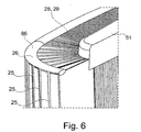
- FIG. 3 shows a sectional view which is orthogonal to the axial extension direction A, as they are in FIG. 2 is drawn.
- the filter element has a substantially oval shape with curved and substantially straight sections.
- Both the filter bellows 10 and the filter bellows 20 have a substantially first curved area 16, 26 as well as a second substantially curved area 17, 27, as well as a first substantially straight area 18, 28 as well as a second substantially straight portion 19, 29.
- the substantially straight portion 18, 28, 19, 29 may also have a curvature, but which is substantially less than the curvature of the curved portions 16, 26, 17, 27.
- curved regions essentially bend over into the substantially straight regions without kinking, so that a substantially oval or even elliptical cross-sectional shape of the filter element results.
- the filter element can be designed narrow and a corresponding opening in an air filter housing are made narrower than in a filter element with an example circular cross section with a comparable filter performance.
- FIG. 4 illustrates the structural configuration of a filter element according to an exemplary embodiment of the invention.
- the outer first filter bellows 10 has a first curved section 16 and a second curved section 17, not shown here due to the section.
- the substantially straight portions 18 and 19 are shown, which are designed without curvature in the embodiment shown here.
- the inclined second inner bellows also has a curved portion 26 and a second curved portion 27, not shown here, and a first substantially straight portion 28 and a second substantially straight portion 29.
- the two substantially straight portions 28, 29 executed without curvature.
- the two straight portions 28, 29 of the second filter bellows 20 are positioned relative to each other so that they are sealed against each other via a sealing member 51 at a first axial end 21 so that a Feasseasseite is tation Kunststoffdicht separated from a raw gas side.
- the shape-preserving shell 60 is here designed such that it extends over the entire depth of the fold of the outer first bellows 10. It should be noted, however, that the sealing element 51 may also extend over the entire depth of the fold of the second bellows, as well as the shape-preserving shell 60 may extend over only a part of the depth of wrinkles of the first bellows 10.
- a further sealing element 52 is provided in the embodiment shown, which seals the filter bellows 10 with respect to the second filter bellows 20 in such a false-tight manner as to ensure a proper filter function is.
- the sealing element 52 extends over the entire pleat depth of the outer bellows 10 as well as the inner bellows 20. It should be understood, however, that the sealing member 51 only partially over the pleat depth of the first bellows 10 or only partially over the pleat depth of the second bellows 20 may extend.
- Both the sealing element 51 as Also, the sealing member 52 may be made of a polyurethane foam, for example, but also of any other material suitable for a seal.
- the bellows 10 may be supported relative to the bellows 20 by a support cage or a support cage 85, so that the inflow and outflow can be kept open even with stronger air flow.
- This basket 85 may for example be attached to the shape-retaining shell 60, so that together with the shape-preserving shell a supporting framework for the mutually inclined filter bellows 10 and 20 results.
- FIG. 5 shows a sectional view in a radial plane of a filter element according to an exemplary embodiment of the invention.
- the contour of the filter element 1 shown here reference is only made to the curved and essentially straight sections with respect to the first outer bellows 10, the information being given analogously for the inner bellows 20.
- FIG. 5 shows an embodiment in which the two substantially straight portions 18, 19 are inclined to each other in a radial sectional plane. They connect the respective curved areas 16 and 17 with each other in such a way that a closed contour results, which can thus be given, for example, the shape of a pear or a drop.
- a facilitated and simplified introduction into an air filter housing can be achieved.
- FIG. 5 shown inclination or inclination in the radial plane is relatively pronounced.
- this inclination or inclination in an actual embodiment can also be significantly lower, in particular when it comes to an optimized design of a filter element, in which the inclination is optimized with respect to the remaining filter parameters.
- the curved regions can transition into the straight regions 18, 19 essentially without kinking.
- Such an arrangement of mutually inclined substantially straight sections is particularly relevant in the case of a radial application of force.
- FIG. 3 illustrates an exemplary embodiment of a second inner bellows.
- a spacer or edge protection 86 is provided which, in particular in the curved region 26 of the second bellows 20 arranged in this area filter folds 25 keeps at a certain distance, so that they are not pressed against each other in an increased air flow and collapse.
- This edge protection or spacer element 86 can be made of the same material as the sealing element 51 and applied in the same manufacturing step.
- the member 86 may be made of a different material, especially if the spacer and edge protection member 86 is also to perform the function of shock or deformation protection, but should not receive the spatial extent as the sealing member 51.
- a hard adhesive in the form of a glue bead are applied, which in this case, for example, has a higher hardness than the material of the sealing element 51st
Landscapes
- Chemical & Material Sciences (AREA)
- Chemical Kinetics & Catalysis (AREA)
- Engineering & Computer Science (AREA)
- Combustion & Propulsion (AREA)
- Mechanical Engineering (AREA)
- General Engineering & Computer Science (AREA)
- Physics & Mathematics (AREA)
- Geometry (AREA)
- Filtering Of Dispersed Particles In Gases (AREA)
Claims (11)
- Élément de filtre à air pour un filtre à air d'un moteur à combustion interne, l'élément filtrant (1) présentant :un premier soufflet de filtre (10) avec des plis de filtre (15) évoluant essentiellement dans une direction d'extension axiale (A) de l'élément filtrant et avec un premier creux de plis évoluant essentiellement dans un plan orthogonal par rapport aux plis de filtre dans une direction d'extension radiale ;un deuxième soufflet de filtre (20) avec des plis de filtre (25) évoluant essentiellement dans une direction d'extension axiale (A) de l'élément filtrant et avec un deuxième creux de plis évoluant essentiellement dans un plan orthogonal par rapport aux plis de filtre dans une direction d'extension radiale, le premier et le deuxième soufflets de filtre (10, 20) présentant chacun une première section courbe (26) et une deuxième section courbe dans un plan de la direction d'extension radiale, avec, entre elles, une première section essentiellement droite et une deuxième section essentiellement droite, de sorte que la première et la deuxième sections courbes ainsi que la première et la deuxième sections essentiellement droites forment un contour circonférentiel ovale fermé ;le deuxième soufflet de filtre (20) étant disposé de manière radiale, à l'intérieur, par rapport au premier soufflet de filtre (10) et, à une première extrémité axiale du deuxième soufflet de filtre, la première section droite étant reliée à la deuxième section droite au moyen d'un premier élément d'étanchéité de sorte qu'un côté de gaz pur et un côté de gaz brut du deuxième soufflet de filtre soient séparés l'un de l'autre de manière étanche aux fuites d'air ;un creux des deuxièmes plis de filtre (25) étant plus profond qu'un creux des premiers plis de filtre correspondants (15), le premier soufflet de filtre et le deuxième soufflet de filtre étant reliés à une deuxième extrémité axiale au moyen d'un deuxième élément d'étanchéité de sorte que les côtés de gaz pur et les côtés de gaz brut du premier soufflet de filtre et/ou du deuxième soufflet de filtre soient séparés l'un de l'autre de manière étanche aux fuites d'air.
- Élément de filtre à air selon la revendication 1, le creux des deuxièmes plis de filtre (25) étant plus profond du facteur 1,1 à 2,5, notamment du facteur 1,2 à 1,9, que le creux des premiers plis de filtre correspondants (15).
- Élément de filtre à air selon l'une des revendications 1 et 2, les plis de filtre (25) du deuxième soufflet de filtre (20) étant inclinés, au moins sur certaines sections, par rapport aux plis de filtre (15) du premier soufflet de filtre (10) dans une direction d'extension axiale (A).
- Élément de filtre à air selon l'une des revendications 1 à 3, une inclinaison des plis de filtre (25) du deuxième soufflet de filtre (20) par rapport à la direction d'extension axiale (A) étant supérieure à une inclinaison des plis de filtre (15) du premier soufflet de filtre (10) par rapport à la direction d'extension axiale (A).
- Élément de filtre à air selon l'une des revendications 1 à 4, le premier soufflet de filtre (10) étant pourvu, au niveau d'une première extrémité axiale (11), d'une coque (60) à la forme stable par rapport à un bord extérieur (13) du premier soufflet de filtre (10).
- Élément de filtre à air selon l'une des revendications 1 à 5, la première section essentiellement droite (18) et la deuxième section essentiellement droite (19) convergeant l'une vers l'autre dans le plan de la direction d'extension radiale.
- Élément de filtre à air selon l'une des revendications 1 à 6, le premier élément d'étanchéité (51) ne s'étendant dans un plan de la direction d'extension radiale que partiellement au-dessus du creux des deuxièmes plis de filtre (25) du deuxième soufflet de filtre (20).
- Élément de filtre à air selon l'une des revendications 1 à 7, le deuxième élément d'étanchéité (52) ne s'étendant dans un plan de la direction d'extension radiale que partiellement au-dessus du creux des premiers plis de filtre (15) et des deuxièmes plis de filtre (25).
- Élément de filtre à air selon l'une des revendications 1 à 8, l'élément d'étanchéité (51, 52, 53) étant constitué de mousse PUR.
- Élément de filtre à air selon l'une des revendications 1 à 9, un côté de gaz pur du premier soufflet de filtre (10) étant orienté vers un côté de gaz pur du deuxième soufflet de filtre (20).
- Élément de filtre à air selon l'une des revendications 1 à 10, le premier soufflet de filtre (10) présentant un premier côté de gaz brut et un premier côté de gaz pur et le deuxième soufflet de filtre (20) présentant un deuxième côté de gaz brut et un deuxième côté de gaz pur, le premier soufflet de filtre (10) et le deuxième soufflet de filtre (20) étant reliés l'un à l'autre de manière étanche aux fuites d'air sur une face frontale du premier soufflet de filtre et sur une face frontale du deuxième soufflet de filtre de sorte que soit un premier espace du côté de gaz brut corresponde à un deuxième espace du côté de gaz brut ou un premier espace du côté de gaz pur corresponde à un deuxième espace du côté de gaz pur.
Priority Applications (1)
| Application Number | Priority Date | Filing Date | Title |
|---|---|---|---|
| EP14179958.5A EP2829309A1 (fr) | 2008-02-26 | 2009-02-26 | Degré d'action d'un filtre à plusieurs soufflets amélioré |
Applications Claiming Priority (3)
| Application Number | Priority Date | Filing Date | Title |
|---|---|---|---|
| DE102008011186A DE102008011186A1 (de) | 2008-02-26 | 2008-02-26 | Filtereinrichtung, insbesondere Luftfilter für eine Brennkraftmaschine |
| DE102008062953A DE102008062953A1 (de) | 2008-12-23 | 2008-12-23 | Wirkungsgrad erhöhter Mehrfachbalgfilter |
| PCT/EP2009/052317 WO2009106589A1 (fr) | 2008-02-26 | 2009-02-26 | Filtre à soufflets multiples, à rendement accru |
Related Child Applications (1)
| Application Number | Title | Priority Date | Filing Date |
|---|---|---|---|
| EP14179958.5A Division EP2829309A1 (fr) | 2008-02-26 | 2009-02-26 | Degré d'action d'un filtre à plusieurs soufflets amélioré |
Publications (2)
| Publication Number | Publication Date |
|---|---|
| EP2249943A1 EP2249943A1 (fr) | 2010-11-17 |
| EP2249943B1 true EP2249943B1 (fr) | 2014-08-27 |
Family
ID=40585466
Family Applications (2)
| Application Number | Title | Priority Date | Filing Date |
|---|---|---|---|
| EP14179958.5A Withdrawn EP2829309A1 (fr) | 2008-02-26 | 2009-02-26 | Degré d'action d'un filtre à plusieurs soufflets amélioré |
| EP09715396.9A Active EP2249943B1 (fr) | 2008-02-26 | 2009-02-26 | Filtre à soufflets multiples, à rendement accru |
Family Applications Before (1)
| Application Number | Title | Priority Date | Filing Date |
|---|---|---|---|
| EP14179958.5A Withdrawn EP2829309A1 (fr) | 2008-02-26 | 2009-02-26 | Degré d'action d'un filtre à plusieurs soufflets amélioré |
Country Status (7)
| Country | Link |
|---|---|
| US (1) | US8979964B2 (fr) |
| EP (2) | EP2829309A1 (fr) |
| JP (1) | JP5635417B2 (fr) |
| KR (1) | KR101618382B1 (fr) |
| CN (1) | CN102015059B (fr) |
| BR (1) | BRPI0908029B1 (fr) |
| WO (1) | WO2009106589A1 (fr) |
Families Citing this family (41)
| Publication number | Priority date | Publication date | Assignee | Title |
|---|---|---|---|---|
| DE102010014277B4 (de) * | 2009-10-12 | 2020-03-12 | Mann+Hummel Gmbh | Filtervorrichtung und Hauptfilterelement für eine Filtervorrichtung |
| FR2967917B1 (fr) * | 2010-11-25 | 2015-12-18 | Airbus Operations Sas | Filtre destine a une bouche d'aspiration d'un systeme confine d'un aeronef |
| IN2014DN00092A (fr) | 2011-07-12 | 2015-05-15 | Nestec Sa | |
| IN2014DN00153A (fr) | 2011-07-12 | 2015-05-22 | Nestec Sa | |
| CA2841241A1 (fr) | 2011-07-12 | 2013-01-17 | Nestec S.A. | Support d'ingredient pour boisson se fermant par pivotement et dote d'un verrou |
| DE102012101185B4 (de) * | 2011-08-03 | 2025-07-10 | Gebr. Becker Gmbh | Filterteil |
| DE102012000482A1 (de) * | 2012-01-13 | 2013-07-18 | Mann + Hummel Gmbh | Luftfilterelement und Luftfilter |
| US10010210B2 (en) | 2012-12-20 | 2018-07-03 | Nestec S.A. | Double ramp for closing a receptacle holder |
| WO2014096122A1 (fr) | 2012-12-20 | 2014-06-26 | Nestec S.A. | Transmission variable de fermeture d'un dispositif de maintien de réceptacle |
| WO2014143778A1 (fr) | 2013-03-15 | 2014-09-18 | Donaldson Company, Inc. | Cartouches de filtre tubulaires ovoïdes et systèmes de filtre les utilisant |
| DE102013015052B4 (de) * | 2013-09-12 | 2015-10-15 | Mann + Hummel Gmbh | Zyklon-Filtereinrichtung |
| DE102014016300B4 (de) * | 2014-11-06 | 2018-05-30 | Mann + Hummel Gmbh | Filter sowie Verwendung eines Hohlfilterelements in diesem Filter |
| US9656199B2 (en) * | 2015-03-04 | 2017-05-23 | Tung-Tsai Lee | Oil mist filter |
| EP3349620B1 (fr) | 2015-09-18 | 2021-01-06 | Société des Produits Nestlé S.A. | Retrait d'une capsule à partir d'un support de capsule |
| DE102015226754A1 (de) * | 2015-12-28 | 2017-06-29 | Mahle International Gmbh | Filtereinrichtung |
| DE202016005074U1 (de) * | 2016-08-22 | 2016-09-21 | Carl Freudenberg Kg | Filterpartrone und Filterpatronenanordnung |
| DE102016011754A1 (de) * | 2016-09-30 | 2018-04-05 | Mann+Hummel Gmbh | Filterelement |
| DE102016012325A1 (de) | 2016-10-17 | 2018-04-19 | Mann + Hummel Gmbh | Rundfilterelement, insbesondere zur Gasfiltration |
| DE102016012330A1 (de) | 2016-10-17 | 2018-04-19 | Mann + Hummel Gmbh | Rundfilterelement, insbesondere zur Gasfiltration |
| DE102017000792B4 (de) | 2017-01-30 | 2022-08-04 | Mann+Hummel Gmbh | Filterelement, Verfahren zu dessen Herstellung und Luftfilter |
| CN107795415A (zh) * | 2017-11-29 | 2018-03-13 | 蚌埠金威滤清器有限公司 | 高效直通式空气滤清器 |
| CN112020387A (zh) | 2018-01-24 | 2020-12-01 | 唐纳森公司 | 过滤器元件、系统和方法 |
| JP7504867B2 (ja) | 2018-08-09 | 2024-06-24 | ソシエテ・デ・プロデュイ・ネスレ・エス・アー | 容易に挿入可能なカップ支持体 |
| CN109772063B (zh) * | 2019-02-28 | 2024-08-02 | 成都易态科技有限公司 | 折叠滤芯 |
| WO2020201469A1 (fr) | 2019-04-05 | 2020-10-08 | Société des Produits Nestlé SA | Dispositif de préparation de boissons à architecture thermiquement optimisée |
| CA3141941A1 (fr) | 2019-06-20 | 2020-12-24 | Societe Des Produits Nestle Sa | Dispositif de preparation de boisson a conditionnement thermique multiple simple |
| US11992800B2 (en) | 2020-11-24 | 2024-05-28 | Cummins Filtration Inc. | Arched air filter |
| PT4452021T (pt) | 2021-12-22 | 2025-12-30 | Nestle Sa | Preparação de bebida com uma válvula de saída flexível |
| EP4452019A1 (fr) | 2021-12-22 | 2024-10-30 | Société des Produits Nestlé S.A. | Préparation de boisson au moyen d'une soupape de sortie stable |
| AU2022419166A1 (en) | 2021-12-22 | 2024-05-09 | Société des Produits Nestlé S.A. | Beverage preparation with compact conditioning chamber |
| CN118369025A (zh) | 2021-12-22 | 2024-07-19 | 雀巢产品有限公司 | 通过稳定胶囊离心进行的饮料制备 |
| EP4452023B1 (fr) | 2021-12-22 | 2026-02-11 | Société des Produits Nestlé S.A. | Préparation de boisson par centrifugation avec transfert de capsule fiable |
| WO2023118247A1 (fr) | 2021-12-22 | 2023-06-29 | Société des Produits Nestlé S.A. | Préparation de boissons par simple transfert de capsules |
| JP2025511669A (ja) | 2022-04-14 | 2025-04-16 | ソシエテ・デ・プロデュイ・ネスレ・エス・アー | カプセル位置決めガイドを有する遠心チャンバ |
| EP4507544A1 (fr) | 2022-04-14 | 2025-02-19 | Société des Produits Nestlé S.A. | Chambre centrifuge avec éléments d'ouverture de capsule |
| EP4507545A1 (fr) | 2022-04-14 | 2025-02-19 | Société des Produits Nestlé S.A. | Chambre de boisson centrifuge avec élément de fixation de fermeture |
| WO2025120121A1 (fr) | 2023-12-07 | 2025-06-12 | Societe Des Produits Nestle S.A. | Réceptacle de capsules usagées pour machines à boisson |
| WO2025120122A1 (fr) | 2023-12-07 | 2025-06-12 | Societe Des Produits Nestle S.A. | Système de distribution de boisson à capsule fiable |
| WO2025120135A1 (fr) | 2023-12-07 | 2025-06-12 | Societe Des Produits Nestle S.A. | Système de retrait de capsule fiable |
| WO2025247763A1 (fr) | 2024-05-27 | 2025-12-04 | Societe Des Produits Nestle S.A. | Machine de préparation de boisson avec sortie |
| WO2026068344A1 (fr) | 2024-09-24 | 2026-04-02 | Societe Des Produits Nestle S.A. | Machine à boissons dotée d'une trappe d'insertion de capsule |
Family Cites Families (17)
| Publication number | Priority date | Publication date | Assignee | Title |
|---|---|---|---|---|
| FR877485A (fr) * | 1940-10-04 | 1942-12-08 | Gaz Et Prot | Filtre pour gazogènes |
| US3333624A (en) * | 1966-06-20 | 1967-08-01 | Southwire Co | Casting wheel cooling method |
| JPS6111397U (ja) | 1984-06-28 | 1986-01-23 | 株式会社 川口技研 | ロ−ル状トイレツトペ−パ−用のホルダ− |
| JPH0410373Y2 (fr) * | 1984-12-27 | 1992-03-13 | ||
| DE3805361A1 (de) * | 1987-02-20 | 1988-09-01 | Sartorius Gmbh | Integralfilter fuer fluide aus mehreren ineinander geschachtelten filterelementen mit unterschiedlichem rueckhaltevermoegen und gehaeuse dafuer |
| JPH0335875Y2 (fr) * | 1987-07-31 | 1991-07-30 | ||
| US5152890A (en) | 1989-10-27 | 1992-10-06 | Pall Corporation | Filter device |
| JPH0735749U (ja) * | 1993-11-30 | 1995-07-04 | 株式会社土屋製作所 | サブエレメント付エアクリーナ |
| JPH08309137A (ja) * | 1995-05-22 | 1996-11-26 | A M Shii:Kk | 集塵機用カートリッジフィルターエレメント |
| DE19547575A1 (de) * | 1995-12-20 | 1997-06-26 | Mann & Hummel Filter | Luftfilterelement |
| JP4344687B2 (ja) | 2002-05-09 | 2009-10-14 | ドナルドソン カンパニー,インコーポレイティド | 縦溝流路濾過媒体を有するエアフィルタ |
| DE10222800B4 (de) | 2002-05-23 | 2013-06-27 | Mann + Hummel Gmbh | Filter in einem Filtergehäuse |
| US20040103626A1 (en) * | 2002-08-23 | 2004-06-03 | Warth Scott B. | Filter element, filter assembly, gas turbine system, and methods |
| WO2005094655A2 (fr) | 2004-03-24 | 2005-10-13 | Donaldson Company, Inc. | Elements filtrants, epurateur d'air, ensemble et procedes |
| US7323106B2 (en) * | 2005-09-01 | 2008-01-29 | Fleetguard, Inc. | Multi-element filter with multiple pleat channel height |
| US20080011673A1 (en) | 2005-09-01 | 2008-01-17 | Janikowski Eric A | Modified Direct Flow Filter |
| US7740678B2 (en) * | 2007-08-07 | 2010-06-22 | Cummins Filtration Ip, Inc. | High capacity filter |
-
2009
- 2009-02-26 WO PCT/EP2009/052317 patent/WO2009106589A1/fr not_active Ceased
- 2009-02-26 CN CN200980114810.7A patent/CN102015059B/zh active Active
- 2009-02-26 JP JP2010548113A patent/JP5635417B2/ja not_active Expired - Fee Related
- 2009-02-26 EP EP14179958.5A patent/EP2829309A1/fr not_active Withdrawn
- 2009-02-26 BR BRPI0908029-5A patent/BRPI0908029B1/pt active IP Right Grant
- 2009-02-26 EP EP09715396.9A patent/EP2249943B1/fr active Active
- 2009-02-26 US US12/228,093 patent/US8979964B2/en active Active
- 2009-02-26 KR KR1020107020855A patent/KR101618382B1/ko not_active Expired - Fee Related
Also Published As
| Publication number | Publication date |
|---|---|
| CN102015059B (zh) | 2014-10-29 |
| KR101618382B1 (ko) | 2016-05-18 |
| KR20100128299A (ko) | 2010-12-07 |
| US20140053521A1 (en) | 2014-02-27 |
| EP2829309A1 (fr) | 2015-01-28 |
| JP2011514949A (ja) | 2011-05-12 |
| EP2249943A1 (fr) | 2010-11-17 |
| BRPI0908029A2 (pt) | 2019-10-01 |
| CN102015059A (zh) | 2011-04-13 |
| WO2009106589A1 (fr) | 2009-09-03 |
| US8979964B2 (en) | 2015-03-17 |
| BRPI0908029B1 (pt) | 2020-10-20 |
| JP5635417B2 (ja) | 2014-12-03 |
Similar Documents
| Publication | Publication Date | Title |
|---|---|---|
| EP2829309A1 (fr) | Degré d'action d'un filtre à plusieurs soufflets amélioré | |
| EP2254680B1 (fr) | Dispositif filtrant, en particulier filtre à air pour un moteur à combustion interne | |
| EP2532408B1 (fr) | Filtre à air doté d'un pré-dépoussiéreur | |
| EP2703059B1 (fr) | Agencement de filtration et procédé de fabrication d'un logement de filtre | |
| EP2254679B1 (fr) | Dispositif filtrant, notamment filtre à air pour un moteur à combustion interne | |
| EP2249944B2 (fr) | Élément filtrant à ensemble de plis optimisé | |
| EP3525910B1 (fr) | Installation de filtre et élément de filtre rond, en particulier pour la filtration de gaz | |
| EP2862614B2 (fr) | Système de filtre équipé d'un élément de filtre | |
| DE102010014277A1 (de) | Filtervorrichtung und Hauptfilterelement für eine Filtervorrichtung | |
| WO2011124675A1 (fr) | Séparateur à cyclone | |
| EP3017854A1 (fr) | Élément creux d'un filtre destiné à filtrer un fluide, filtre, carter de filtre et joint d'un élément creux de filtre | |
| DE102014016300B4 (de) | Filter sowie Verwendung eines Hohlfilterelements in diesem Filter | |
| DE102011120387A1 (de) | Luftfilteranordnung und Filtervorrichtung mit einer Luftfilteranordnung | |
| EP4426467B1 (fr) | Élément filtrant rond et dispositif filtrant | |
| DE102008062954B4 (de) | Filtereinrichtung, insbesondere Luftfilter für eine Brennkraftmaschine | |
| EP2702261B1 (fr) | Élément de filtration d'air et boîtier pour élément de filtration d'air | |
| DE102008062953A1 (de) | Wirkungsgrad erhöhter Mehrfachbalgfilter | |
| DE202018000744U1 (de) | Luftfilter mit geringem Druckverlust | |
| DE102014012944A1 (de) | Filtersystem mit Filterelement | |
| WO2025087748A1 (fr) | Élément filtrant et système de filtration |
Legal Events
| Date | Code | Title | Description |
|---|---|---|---|
| PUAI | Public reference made under article 153(3) epc to a published international application that has entered the european phase |
Free format text: ORIGINAL CODE: 0009012 |
|
| 17P | Request for examination filed |
Effective date: 20100820 |
|
| AK | Designated contracting states |
Kind code of ref document: A1 Designated state(s): AT BE BG CH CY CZ DE DK EE ES FI FR GB GR HR HU IE IS IT LI LT LU LV MC MK MT NL NO PL PT RO SE SI SK TR |
|
| AX | Request for extension of the european patent |
Extension state: AL BA RS |
|
| RIN1 | Information on inventor provided before grant (corrected) |
Inventor name: MUENKEL, KARLHEINZ Inventor name: BECKER, STEFAN Inventor name: KOLCZYK, MARKUS Inventor name: HEIM, MICHAEL |
|
| DAX | Request for extension of the european patent (deleted) | ||
| 17Q | First examination report despatched |
Effective date: 20111205 |
|
| GRAP | Despatch of communication of intention to grant a patent |
Free format text: ORIGINAL CODE: EPIDOSNIGR1 |
|
| GRAS | Grant fee paid |
Free format text: ORIGINAL CODE: EPIDOSNIGR3 |
|
| INTG | Intention to grant announced |
Effective date: 20140317 |
|
| GRAA | (expected) grant |
Free format text: ORIGINAL CODE: 0009210 |
|
| AK | Designated contracting states |
Kind code of ref document: B1 Designated state(s): AT BE BG CH CY CZ DE DK EE ES FI FR GB GR HR HU IE IS IT LI LT LU LV MC MK MT NL NO PL PT RO SE SI SK TR |
|
| REG | Reference to a national code |
Ref country code: GB Ref legal event code: FG4D Free format text: NOT ENGLISH |
|
| REG | Reference to a national code |
Ref country code: CH Ref legal event code: EP |
|
| REG | Reference to a national code |
Ref country code: AT Ref legal event code: REF Ref document number: 684226 Country of ref document: AT Kind code of ref document: T Effective date: 20140915 |
|
| REG | Reference to a national code |
Ref country code: IE Ref legal event code: FG4D Free format text: LANGUAGE OF EP DOCUMENT: GERMAN |
|
| REG | Reference to a national code |
Ref country code: DE Ref legal event code: R096 Ref document number: 502009009859 Country of ref document: DE Effective date: 20141009 |
|
| REG | Reference to a national code |
Ref country code: LT Ref legal event code: MG4D |
|
| REG | Reference to a national code |
Ref country code: NL Ref legal event code: VDEP Effective date: 20140827 |
|
| PG25 | Lapsed in a contracting state [announced via postgrant information from national office to epo] |
Ref country code: GR Free format text: LAPSE BECAUSE OF FAILURE TO SUBMIT A TRANSLATION OF THE DESCRIPTION OR TO PAY THE FEE WITHIN THE PRESCRIBED TIME-LIMIT Effective date: 20141128 Ref country code: BG Free format text: LAPSE BECAUSE OF FAILURE TO SUBMIT A TRANSLATION OF THE DESCRIPTION OR TO PAY THE FEE WITHIN THE PRESCRIBED TIME-LIMIT Effective date: 20141127 Ref country code: LT Free format text: LAPSE BECAUSE OF FAILURE TO SUBMIT A TRANSLATION OF THE DESCRIPTION OR TO PAY THE FEE WITHIN THE PRESCRIBED TIME-LIMIT Effective date: 20140827 Ref country code: FI Free format text: LAPSE BECAUSE OF FAILURE TO SUBMIT A TRANSLATION OF THE DESCRIPTION OR TO PAY THE FEE WITHIN THE PRESCRIBED TIME-LIMIT Effective date: 20140827 Ref country code: SE Free format text: LAPSE BECAUSE OF FAILURE TO SUBMIT A TRANSLATION OF THE DESCRIPTION OR TO PAY THE FEE WITHIN THE PRESCRIBED TIME-LIMIT Effective date: 20140827 Ref country code: PT Free format text: LAPSE BECAUSE OF FAILURE TO SUBMIT A TRANSLATION OF THE DESCRIPTION OR TO PAY THE FEE WITHIN THE PRESCRIBED TIME-LIMIT Effective date: 20141229 Ref country code: NO Free format text: LAPSE BECAUSE OF FAILURE TO SUBMIT A TRANSLATION OF THE DESCRIPTION OR TO PAY THE FEE WITHIN THE PRESCRIBED TIME-LIMIT Effective date: 20141127 Ref country code: ES Free format text: LAPSE BECAUSE OF FAILURE TO SUBMIT A TRANSLATION OF THE DESCRIPTION OR TO PAY THE FEE WITHIN THE PRESCRIBED TIME-LIMIT Effective date: 20140827 |
|
| PG25 | Lapsed in a contracting state [announced via postgrant information from national office to epo] |
Ref country code: CY Free format text: LAPSE BECAUSE OF FAILURE TO SUBMIT A TRANSLATION OF THE DESCRIPTION OR TO PAY THE FEE WITHIN THE PRESCRIBED TIME-LIMIT Effective date: 20140827 Ref country code: IS Free format text: LAPSE BECAUSE OF FAILURE TO SUBMIT A TRANSLATION OF THE DESCRIPTION OR TO PAY THE FEE WITHIN THE PRESCRIBED TIME-LIMIT Effective date: 20141227 Ref country code: LV Free format text: LAPSE BECAUSE OF FAILURE TO SUBMIT A TRANSLATION OF THE DESCRIPTION OR TO PAY THE FEE WITHIN THE PRESCRIBED TIME-LIMIT Effective date: 20140827 Ref country code: HR Free format text: LAPSE BECAUSE OF FAILURE TO SUBMIT A TRANSLATION OF THE DESCRIPTION OR TO PAY THE FEE WITHIN THE PRESCRIBED TIME-LIMIT Effective date: 20140827 |
|
| PG25 | Lapsed in a contracting state [announced via postgrant information from national office to epo] |
Ref country code: NL Free format text: LAPSE BECAUSE OF FAILURE TO SUBMIT A TRANSLATION OF THE DESCRIPTION OR TO PAY THE FEE WITHIN THE PRESCRIBED TIME-LIMIT Effective date: 20140827 |
|
| PG25 | Lapsed in a contracting state [announced via postgrant information from national office to epo] |
Ref country code: IT Free format text: LAPSE BECAUSE OF FAILURE TO SUBMIT A TRANSLATION OF THE DESCRIPTION OR TO PAY THE FEE WITHIN THE PRESCRIBED TIME-LIMIT Effective date: 20140827 Ref country code: CZ Free format text: LAPSE BECAUSE OF FAILURE TO SUBMIT A TRANSLATION OF THE DESCRIPTION OR TO PAY THE FEE WITHIN THE PRESCRIBED TIME-LIMIT Effective date: 20140827 Ref country code: SK Free format text: LAPSE BECAUSE OF FAILURE TO SUBMIT A TRANSLATION OF THE DESCRIPTION OR TO PAY THE FEE WITHIN THE PRESCRIBED TIME-LIMIT Effective date: 20140827 Ref country code: DK Free format text: LAPSE BECAUSE OF FAILURE TO SUBMIT A TRANSLATION OF THE DESCRIPTION OR TO PAY THE FEE WITHIN THE PRESCRIBED TIME-LIMIT Effective date: 20140827 Ref country code: RO Free format text: LAPSE BECAUSE OF FAILURE TO SUBMIT A TRANSLATION OF THE DESCRIPTION OR TO PAY THE FEE WITHIN THE PRESCRIBED TIME-LIMIT Effective date: 20140827 Ref country code: EE Free format text: LAPSE BECAUSE OF FAILURE TO SUBMIT A TRANSLATION OF THE DESCRIPTION OR TO PAY THE FEE WITHIN THE PRESCRIBED TIME-LIMIT Effective date: 20140827 |
|
| REG | Reference to a national code |
Ref country code: DE Ref legal event code: R097 Ref document number: 502009009859 Country of ref document: DE |
|
| PG25 | Lapsed in a contracting state [announced via postgrant information from national office to epo] |
Ref country code: PL Free format text: LAPSE BECAUSE OF FAILURE TO SUBMIT A TRANSLATION OF THE DESCRIPTION OR TO PAY THE FEE WITHIN THE PRESCRIBED TIME-LIMIT Effective date: 20140827 |
|
| PG25 | Lapsed in a contracting state [announced via postgrant information from national office to epo] |
Ref country code: BE Free format text: LAPSE BECAUSE OF NON-PAYMENT OF DUE FEES Effective date: 20150228 |
|
| PLBE | No opposition filed within time limit |
Free format text: ORIGINAL CODE: 0009261 |
|
| STAA | Information on the status of an ep patent application or granted ep patent |
Free format text: STATUS: NO OPPOSITION FILED WITHIN TIME LIMIT |
|
| 26N | No opposition filed |
Effective date: 20150528 |
|
| PG25 | Lapsed in a contracting state [announced via postgrant information from national office to epo] |
Ref country code: LU Free format text: LAPSE BECAUSE OF FAILURE TO SUBMIT A TRANSLATION OF THE DESCRIPTION OR TO PAY THE FEE WITHIN THE PRESCRIBED TIME-LIMIT Effective date: 20150226 |
|
| REG | Reference to a national code |
Ref country code: CH Ref legal event code: PL |
|
| PG25 | Lapsed in a contracting state [announced via postgrant information from national office to epo] |
Ref country code: MC Free format text: LAPSE BECAUSE OF FAILURE TO SUBMIT A TRANSLATION OF THE DESCRIPTION OR TO PAY THE FEE WITHIN THE PRESCRIBED TIME-LIMIT Effective date: 20140827 Ref country code: CH Free format text: LAPSE BECAUSE OF NON-PAYMENT OF DUE FEES Effective date: 20150228 Ref country code: LI Free format text: LAPSE BECAUSE OF NON-PAYMENT OF DUE FEES Effective date: 20150228 |
|
| REG | Reference to a national code |
Ref country code: IE Ref legal event code: MM4A |
|
| PG25 | Lapsed in a contracting state [announced via postgrant information from national office to epo] |
Ref country code: SI Free format text: LAPSE BECAUSE OF FAILURE TO SUBMIT A TRANSLATION OF THE DESCRIPTION OR TO PAY THE FEE WITHIN THE PRESCRIBED TIME-LIMIT Effective date: 20140827 |
|
| PG25 | Lapsed in a contracting state [announced via postgrant information from national office to epo] |
Ref country code: IE Free format text: LAPSE BECAUSE OF NON-PAYMENT OF DUE FEES Effective date: 20150226 |
|
| REG | Reference to a national code |
Ref country code: FR Ref legal event code: PLFP Year of fee payment: 8 |
|
| REG | Reference to a national code |
Ref country code: AT Ref legal event code: MM01 Ref document number: 684226 Country of ref document: AT Kind code of ref document: T Effective date: 20150226 |
|
| PG25 | Lapsed in a contracting state [announced via postgrant information from national office to epo] |
Ref country code: AT Free format text: LAPSE BECAUSE OF NON-PAYMENT OF DUE FEES Effective date: 20150226 |
|
| PG25 | Lapsed in a contracting state [announced via postgrant information from national office to epo] |
Ref country code: MT Free format text: LAPSE BECAUSE OF FAILURE TO SUBMIT A TRANSLATION OF THE DESCRIPTION OR TO PAY THE FEE WITHIN THE PRESCRIBED TIME-LIMIT Effective date: 20140827 |
|
| REG | Reference to a national code |
Ref country code: FR Ref legal event code: PLFP Year of fee payment: 9 |
|
| PG25 | Lapsed in a contracting state [announced via postgrant information from national office to epo] |
Ref country code: HU Free format text: LAPSE BECAUSE OF FAILURE TO SUBMIT A TRANSLATION OF THE DESCRIPTION OR TO PAY THE FEE WITHIN THE PRESCRIBED TIME-LIMIT; INVALID AB INITIO Effective date: 20090226 |
|
| PG25 | Lapsed in a contracting state [announced via postgrant information from national office to epo] |
Ref country code: TR Free format text: LAPSE BECAUSE OF FAILURE TO SUBMIT A TRANSLATION OF THE DESCRIPTION OR TO PAY THE FEE WITHIN THE PRESCRIBED TIME-LIMIT Effective date: 20140827 |
|
| REG | Reference to a national code |
Ref country code: FR Ref legal event code: PLFP Year of fee payment: 10 |
|
| PG25 | Lapsed in a contracting state [announced via postgrant information from national office to epo] |
Ref country code: MK Free format text: LAPSE BECAUSE OF FAILURE TO SUBMIT A TRANSLATION OF THE DESCRIPTION OR TO PAY THE FEE WITHIN THE PRESCRIBED TIME-LIMIT Effective date: 20140827 |
|
| REG | Reference to a national code |
Ref country code: DE Ref legal event code: R081 Ref document number: 502009009859 Country of ref document: DE Owner name: MANN+HUMMEL GMBH, DE Free format text: FORMER OWNER: MANN + HUMMEL GMBH, 71638 LUDWIGSBURG, DE |
|
| P01 | Opt-out of the competence of the unified patent court (upc) registered |
Effective date: 20230627 |
|
| PGFP | Annual fee paid to national office [announced via postgrant information from national office to epo] |
Ref country code: GB Payment date: 20260219 Year of fee payment: 18 |
|
| PGFP | Annual fee paid to national office [announced via postgrant information from national office to epo] |
Ref country code: DE Payment date: 20260218 Year of fee payment: 18 |
|
| PGFP | Annual fee paid to national office [announced via postgrant information from national office to epo] |
Ref country code: FR Payment date: 20260218 Year of fee payment: 18 |