EP2249948B1 - Procédé et dispositif de séparation de gaz étrangers contenus dans un gaz utile réducteur par adsorption modulée en pression à vapeur - Google Patents
Procédé et dispositif de séparation de gaz étrangers contenus dans un gaz utile réducteur par adsorption modulée en pression à vapeur Download PDFInfo
- Publication number
- EP2249948B1 EP2249948B1 EP09716244.0A EP09716244A EP2249948B1 EP 2249948 B1 EP2249948 B1 EP 2249948B1 EP 09716244 A EP09716244 A EP 09716244A EP 2249948 B1 EP2249948 B1 EP 2249948B1
- Authority
- EP
- European Patent Office
- Prior art keywords
- gas
- ejector
- swing adsorption
- useful gas
- pressure swing
- Prior art date
- Legal status (The legal status is an assumption and is not a legal conclusion. Google has not performed a legal analysis and makes no representation as to the accuracy of the status listed.)
- Not-in-force
Links
Images

Classifications
-
- B—PERFORMING OPERATIONS; TRANSPORTING
- B01—PHYSICAL OR CHEMICAL PROCESSES OR APPARATUS IN GENERAL
- B01D—SEPARATION
- B01D53/00—Separation of gases or vapours; Recovering vapours of volatile solvents from gases; Chemical or biological purification of waste gases, e.g. engine exhaust gases, smoke, fumes, flue gases, aerosols
- B01D53/02—Separation of gases or vapours; Recovering vapours of volatile solvents from gases; Chemical or biological purification of waste gases, e.g. engine exhaust gases, smoke, fumes, flue gases, aerosols by adsorption, e.g. preparative gas chromatography
- B01D53/04—Separation of gases or vapours; Recovering vapours of volatile solvents from gases; Chemical or biological purification of waste gases, e.g. engine exhaust gases, smoke, fumes, flue gases, aerosols by adsorption, e.g. preparative gas chromatography with stationary adsorbents
- B01D53/047—Pressure swing adsorption
- B01D53/0476—Vacuum pressure swing adsorption
-
- C—CHEMISTRY; METALLURGY
- C01—INORGANIC CHEMISTRY
- C01B—NON-METALLIC ELEMENTS; COMPOUNDS THEREOF; METALLOIDS OR COMPOUNDS THEREOF NOT COVERED BY SUBCLASS C01C
- C01B3/00—Hydrogen; Gaseous mixtures containing hydrogen; Separation of hydrogen from mixtures containing it; Purification of hydrogen; Reversible storage of hydrogen
- C01B3/02—Production of hydrogen; Production of gaseous mixtures containing hydrogen
- C01B3/32—Production of hydrogen; Production of gaseous mixtures containing hydrogen by reaction of gaseous or liquid organic compounds with gasifying agents, e.g. water, carbon dioxide or air
- C01B3/34—Production of hydrogen; Production of gaseous mixtures containing hydrogen by reaction of gaseous or liquid organic compounds with gasifying agents, e.g. water, carbon dioxide or air by reaction of hydrocarbons with gasifying agents
-
- C—CHEMISTRY; METALLURGY
- C01—INORGANIC CHEMISTRY
- C01B—NON-METALLIC ELEMENTS; COMPOUNDS THEREOF; METALLOIDS OR COMPOUNDS THEREOF NOT COVERED BY SUBCLASS C01C
- C01B3/00—Hydrogen; Gaseous mixtures containing hydrogen; Separation of hydrogen from mixtures containing it; Purification of hydrogen; Reversible storage of hydrogen
- C01B3/50—Separation of hydrogen or hydrogen-containing gases from gaseous mixtures, e.g. purification
- C01B3/56—Separation of hydrogen or hydrogen-containing gases from gaseous mixtures, e.g. purification by contacting with solids; Regeneration of used solids
-
- B—PERFORMING OPERATIONS; TRANSPORTING
- B01—PHYSICAL OR CHEMICAL PROCESSES OR APPARATUS IN GENERAL
- B01D—SEPARATION
- B01D2256/00—Main component in the product gas stream after treatment
- B01D2256/16—Hydrogen
-
- B—PERFORMING OPERATIONS; TRANSPORTING
- B01—PHYSICAL OR CHEMICAL PROCESSES OR APPARATUS IN GENERAL
- B01D—SEPARATION
- B01D2257/00—Components to be removed
- B01D2257/50—Carbon oxides
- B01D2257/504—Carbon dioxide
-
- C—CHEMISTRY; METALLURGY
- C01—INORGANIC CHEMISTRY
- C01B—NON-METALLIC ELEMENTS; COMPOUNDS THEREOF; METALLOIDS OR COMPOUNDS THEREOF NOT COVERED BY SUBCLASS C01C
- C01B2203/00—Integrated processes for the production of hydrogen or synthesis gas
- C01B2203/02—Processes for making hydrogen or synthesis gas
- C01B2203/0205—Processes for making hydrogen or synthesis gas containing a reforming step
- C01B2203/0227—Processes for making hydrogen or synthesis gas containing a reforming step containing a catalytic reforming step
- C01B2203/0233—Processes for making hydrogen or synthesis gas containing a reforming step containing a catalytic reforming step the reforming step being a steam reforming step
-
- C—CHEMISTRY; METALLURGY
- C01—INORGANIC CHEMISTRY
- C01B—NON-METALLIC ELEMENTS; COMPOUNDS THEREOF; METALLOIDS OR COMPOUNDS THEREOF NOT COVERED BY SUBCLASS C01C
- C01B2203/00—Integrated processes for the production of hydrogen or synthesis gas
- C01B2203/04—Integrated processes for the production of hydrogen or synthesis gas containing a purification step for the hydrogen or the synthesis gas
- C01B2203/042—Purification by adsorption on solids
- C01B2203/043—Regenerative adsorption process in two or more beds, one for adsorption, the other for regeneration
-
- C—CHEMISTRY; METALLURGY
- C01—INORGANIC CHEMISTRY
- C01B—NON-METALLIC ELEMENTS; COMPOUNDS THEREOF; METALLOIDS OR COMPOUNDS THEREOF NOT COVERED BY SUBCLASS C01C
- C01B2203/00—Integrated processes for the production of hydrogen or synthesis gas
- C01B2203/04—Integrated processes for the production of hydrogen or synthesis gas containing a purification step for the hydrogen or the synthesis gas
- C01B2203/0435—Catalytic purification
- C01B2203/044—Selective oxidation of carbon monoxide
-
- C—CHEMISTRY; METALLURGY
- C01—INORGANIC CHEMISTRY
- C01B—NON-METALLIC ELEMENTS; COMPOUNDS THEREOF; METALLOIDS OR COMPOUNDS THEREOF NOT COVERED BY SUBCLASS C01C
- C01B2203/00—Integrated processes for the production of hydrogen or synthesis gas
- C01B2203/04—Integrated processes for the production of hydrogen or synthesis gas containing a purification step for the hydrogen or the synthesis gas
- C01B2203/0465—Composition of the impurity
- C01B2203/047—Composition of the impurity the impurity being carbon monoxide
-
- C—CHEMISTRY; METALLURGY
- C01—INORGANIC CHEMISTRY
- C01B—NON-METALLIC ELEMENTS; COMPOUNDS THEREOF; METALLOIDS OR COMPOUNDS THEREOF NOT COVERED BY SUBCLASS C01C
- C01B2203/00—Integrated processes for the production of hydrogen or synthesis gas
- C01B2203/04—Integrated processes for the production of hydrogen or synthesis gas containing a purification step for the hydrogen or the synthesis gas
- C01B2203/0465—Composition of the impurity
- C01B2203/0475—Composition of the impurity the impurity being carbon dioxide
-
- C—CHEMISTRY; METALLURGY
- C01—INORGANIC CHEMISTRY
- C01B—NON-METALLIC ELEMENTS; COMPOUNDS THEREOF; METALLOIDS OR COMPOUNDS THEREOF NOT COVERED BY SUBCLASS C01C
- C01B2203/00—Integrated processes for the production of hydrogen or synthesis gas
- C01B2203/04—Integrated processes for the production of hydrogen or synthesis gas containing a purification step for the hydrogen or the synthesis gas
- C01B2203/0465—Composition of the impurity
- C01B2203/0495—Composition of the impurity the impurity being water
-
- C—CHEMISTRY; METALLURGY
- C01—INORGANIC CHEMISTRY
- C01B—NON-METALLIC ELEMENTS; COMPOUNDS THEREOF; METALLOIDS OR COMPOUNDS THEREOF NOT COVERED BY SUBCLASS C01C
- C01B2203/00—Integrated processes for the production of hydrogen or synthesis gas
- C01B2203/08—Methods of heating or cooling
- C01B2203/0805—Methods of heating the process for making hydrogen or synthesis gas
- C01B2203/0838—Methods of heating the process for making hydrogen or synthesis gas by heat exchange with exothermic reactions, other than by combustion of fuel
-
- C—CHEMISTRY; METALLURGY
- C01—INORGANIC CHEMISTRY
- C01B—NON-METALLIC ELEMENTS; COMPOUNDS THEREOF; METALLOIDS OR COMPOUNDS THEREOF NOT COVERED BY SUBCLASS C01C
- C01B2203/00—Integrated processes for the production of hydrogen or synthesis gas
- C01B2203/08—Methods of heating or cooling
- C01B2203/0872—Methods of cooling
- C01B2203/0883—Methods of cooling by indirect heat exchange
-
- C—CHEMISTRY; METALLURGY
- C01—INORGANIC CHEMISTRY
- C01B—NON-METALLIC ELEMENTS; COMPOUNDS THEREOF; METALLOIDS OR COMPOUNDS THEREOF NOT COVERED BY SUBCLASS C01C
- C01B2203/00—Integrated processes for the production of hydrogen or synthesis gas
- C01B2203/14—Details of the flowsheet
- C01B2203/148—Details of the flowsheet involving a recycle stream to the feed of the process for making hydrogen or synthesis gas
-
- C—CHEMISTRY; METALLURGY
- C01—INORGANIC CHEMISTRY
- C01B—NON-METALLIC ELEMENTS; COMPOUNDS THEREOF; METALLOIDS OR COMPOUNDS THEREOF NOT COVERED BY SUBCLASS C01C
- C01B2203/00—Integrated processes for the production of hydrogen or synthesis gas
- C01B2203/80—Aspect of integrated processes for the production of hydrogen or synthesis gas not covered by groups C01B2203/02 - C01B2203/1695
- C01B2203/84—Energy production
-
- Y—GENERAL TAGGING OF NEW TECHNOLOGICAL DEVELOPMENTS; GENERAL TAGGING OF CROSS-SECTIONAL TECHNOLOGIES SPANNING OVER SEVERAL SECTIONS OF THE IPC; TECHNICAL SUBJECTS COVERED BY FORMER USPC CROSS-REFERENCE ART COLLECTIONS [XRACs] AND DIGESTS
- Y02—TECHNOLOGIES OR APPLICATIONS FOR MITIGATION OR ADAPTATION AGAINST CLIMATE CHANGE
- Y02C—CAPTURE, STORAGE, SEQUESTRATION OR DISPOSAL OF GREENHOUSE GASES [GHG]
- Y02C20/00—Capture or disposal of greenhouse gases
- Y02C20/40—Capture or disposal of greenhouse gases of CO2
-
- Y—GENERAL TAGGING OF NEW TECHNOLOGICAL DEVELOPMENTS; GENERAL TAGGING OF CROSS-SECTIONAL TECHNOLOGIES SPANNING OVER SEVERAL SECTIONS OF THE IPC; TECHNICAL SUBJECTS COVERED BY FORMER USPC CROSS-REFERENCE ART COLLECTIONS [XRACs] AND DIGESTS
- Y02—TECHNOLOGIES OR APPLICATIONS FOR MITIGATION OR ADAPTATION AGAINST CLIMATE CHANGE
- Y02P—CLIMATE CHANGE MITIGATION TECHNOLOGIES IN THE PRODUCTION OR PROCESSING OF GOODS
- Y02P20/00—Technologies relating to chemical industry
- Y02P20/151—Reduction of greenhouse gas [GHG] emissions, e.g. CO2
-
- Y—GENERAL TAGGING OF NEW TECHNOLOGICAL DEVELOPMENTS; GENERAL TAGGING OF CROSS-SECTIONAL TECHNOLOGIES SPANNING OVER SEVERAL SECTIONS OF THE IPC; TECHNICAL SUBJECTS COVERED BY FORMER USPC CROSS-REFERENCE ART COLLECTIONS [XRACs] AND DIGESTS
- Y02—TECHNOLOGIES OR APPLICATIONS FOR MITIGATION OR ADAPTATION AGAINST CLIMATE CHANGE
- Y02P—CLIMATE CHANGE MITIGATION TECHNOLOGIES IN THE PRODUCTION OR PROCESSING OF GOODS
- Y02P30/00—Technologies relating to oil refining and petrochemical industry
Definitions
- the invention relates to a method for purifying a reducing useful gas by pressure swing adsorption using a so-called ejector, which is driven by a pressurized gas and generates a vacuum which improves the desorption of the pressure swing adsorption unit, wherein the invention uses steam as a pressurized gas, which is generated by the heater for producing the Nutzgases.
- the invention also relates to a device having an ejector driven by steam and whose vacuum is used to more desorb a pressure swing adsorption unit.
- reducing gases are commonly performed process in the art.
- An example of the production of a reducing gas is the steam reforming process.
- synthesis gas By heating a hydrocarbon-containing starting mixture with steam, for example, synthesis gas can be produced, which is a mixture of hydrogen, carbon monoxide and carbon dioxide.
- Synthesis gas is very often used as a fuel gas or as a starting material for chemical syntheses.
- Another commonly-used reducing gas is carbon monoxide.
- the reducing gas must be free of associated gases.
- a frequently occurring accompanying gas is carbon dioxide, which arises during the combustion or reforming processes. Converting the carbon monoxide from the synthesis gas by a so-called CO conversion in the presence of water vapor, we obtain a mixture of hydrogen and carbon dioxide. The latter can be removed from the synthesis gas by various methods. By removing the carbon dioxide, pure hydrogen is obtained, which is an important raw material for many syntheses and applications.
- Other, frequently occurring associated gases or foreign gases or foreign gas components, which are undesirable in reducing gases and must be separated, are residual gas components such as methane and nitrogen.
- gas scrubbing processes are used to separate the unwanted associated gases, which are suitable for the purposes mentioned.
- pressure swing adsorption systems are used, which intercept the gas to be separated by adsorption. pressure adsorption can almost completely remove foreign gases by adsorption, which is only possible to a limited extent by gas washing processes.
- Pressure swing adsorption systems use the adsorption capacity of adsorbent materials.
- adsorbent materials are activated carbon, molecular sieves, silica gel or zeolites.
- the adsorbent materials are packed in suitable containers which are flowed under pressure by the gas to be purified. In the process, the foreign gas components are adsorbed and the purified useful gas is obtained. After a certain time, the absorption capacity of the adsorbent material is exhausted. The container is expanded and purged with Nutzgas so that the adsorbent material releases the adsorbed foreign gas. This is then sent for further use or disposal.
- the processes of adsorption and desorption are carried out in cyclic alternation in order to be able to continuously purify supplied useful gas.
- the process of desorption after relaxation can be assisted by applying a vacuum.
- the adsorbed foreign gas can be almost completely removed from the adsorbent material.
- the adsorbent material is then completely available again for an adsorption process.
- a so-called ejector is used. This uses the pressure of the outflowing gas by exploiting the Venturi effect to generate vacuum. By means of a suitable valve circuit, in which the outflowing gas flows through the ejector, a sufficient evacuation of the pressure swing adsorption vessels can then be achieved.
- the EP 015413 B1 describes a pressure swing adsorption process that provides an array of pressure swing adsorption units that cyclically displaces a gas mixture by selectively adsorbing one or more constituents of the gas therefrom.
- a vacuum is used, which is generated by means of an ejector.
- the ejector is operated by the pressure of the gases flowing out of the pressure change units, whereby by suitable combination of the pressure swing adsorption units and valve circuits both the outflowing useful gas and the outflowing desorbed foreign gas can be utilized.
- the EP 1101731 A1 describes a process for the production of synthesis gas in conjunction with a pressure swing adsorption plant, by which the synthesis gas is freed of entrained carbon dioxide.
- the vacuum for desorption of the pressure change unit is generated by an ejector, wherein the ejector to operate the high pressure under which the heating gas is in the supply, exploits.
- the gas leaving the ejector can be used again as fuel gas.
- both the fuel gas and the vacuum of the respective capacity can be adjusted.
- the vacuum created by the ejectors is insufficient. For this reason, it is necessary to use devices that can further increase the vacuum. This is expensive and usually associated with high costs. Also, the pressure of the effluent gas is not always high enough to operate the ejector to produce a sufficient vacuum. The use of compressed gas is inconvenient for cost reasons. Therefore, a cheap way to operate the ejectors with improved efficiency is sought.
- the EP 864351 A2 describes a method of performing a vacuum swing absorption wherein air is separated into an oxygen-enriched and an oxygen-depleted stream, and the vacuum for vacuum swing absorption by steam under pressure is generated, and the pressurized steam is generated by an exothermic chemical reaction involving the oxygen-enriched stream is supplied and in which the oxygen is a reactant.
- the generation of the vacuum by the steam is carried out by at least one so-called eductor.
- the method is not suitable for the separation of usable gases from a gas mixture, since the separated oxygen-enriched gas is used to generate the steam. Furthermore, the separated gases are not under pressure.
- the invention solves this problem by the method according to claim 1 or the device according to claim 9.
- the invention also provides a solution for adapting the vacuum during the desorption process to the respective requirements, so that the capacity of the pressure change unit can be optimized.
- a system of storage tanks which are available as buffer tanks for vacuum and desorbed gases.
- the system according to the invention for operating a pressure swing adsorption unit is very well suited to the operation of steam reforming processes.
- the inventive system for operating pressure swing adsorption units is in principle suitable for any process that produces a reducing gas, cleans by pressure swing adsorption and provides hot flue gases and hot gases available, with which steam can be produced to operate an ejector.
- the steam for the operation of the ejector can be generated according to the invention both in the embodiment of the heating gas and in the execution device for the working gas.
- the steam generation can also be carried out at both positions in the process flow, wherein the resulting vapor streams can then be mixed as desired and are transported by appropriate pipes in the ejector.
- a steam generator is used as a heat exchanger only at one of the said positions in the process flow, a normal type of cooler, such as an air cooler, may be located at one of the other positions where no steam is generated. After these process steps, a cooled synthesis gas is obtained.
- the invention also claims a method of condensing the steam to operate the ejector so that it can be recycled back to the process of producing the vapor. It is also possible to supply the condensed vapor to the process for generating the useful gas. In principle, it is possible to use the condensed vapor for any purpose.
- the process for generating the useful gas is a reforming process that uses a hydrocarbon-containing source gas to produce synthesis gas with steam through a reforming process at elevated temperature.
- the hydrocarbon-containing starting gas used is preferably natural gas.
- LPG gas or a liquefied gas It is also possible to use naphtha or mineral spirits and all other substances which are suitable as feedstock for a reforming process.
- the inventive process for operating the ejector can finally be used in principle in all other processes for generating reducing gases.
- a pressure swing adsorption unit according to the invention in a process for the gasification of coal.
- a suitable process for the conversion of carbon monoxide into carbon dioxide describes the EP 1878782 A1 ,
- the process of the conversion is preceded by a cooling of the synthesis gas, wherein this cooling can be used as a heat exchange process or for steam generation.
- Steam can also be generated behind the process step of the heat-generating CO conversion and this can be fed into the vapor flow for the operation of the ejector. If no steam generator is provided behind the process step for the conversion, then there can also be a normal cooler there. After these processes, a cooled carbon monoxide-free synthesis gas is obtained.
- a pressure swing adsorption plant In order to remove the carbon dioxide completely from the synthesis gas, a pressure swing adsorption plant is usually used. It is possible to use these alone or in conjunction with any sour gas scrubbing. With a small proportion of gases to be adsorbed, the operation of a pressure swing adsorption system without previous acid gas scrubbing is generally sufficient.
- the pressure swing adsorption can be simple to remove the acid gas and loaded at atmospheric pressure, so that only for desorption of the loaded adsorbent, a negative pressure must be applied.
- the pressure swing adsorption can be operated continuously, so that the adsorption of the gas to be adsorbed takes place only by the adsorption force of the adsorbent. In an advantageous and preferred embodiment, however, the pressure swing adsorption unit is operated at overpressure in order to make better use of the adsorption force of the adsorbent.
- Typical pressures for operating a pressure swing adsorption unit are pressures of 5 to 50 bar.
- the unit is relaxed. Nevertheless, in order to be able to operate the process continuously, the adsorption must be carried out in cyclic change with desorption.
- batteries are usually used in which 5 to 50 units are operated side by side for pressure swing adsorption.
- a part of the units is flowed under increased pressure of the gas to be purified, whereby the foreign gas is retained by the adsorbent.
- the purified useful gas is obtained.
- Another part of the units is expanded, whereby the adsorbed gas is released in admixture with the useful gas. During the subsequent evacuation of the vessel, essentially the desorbed foreign gas is recovered.
- the relaxation and desorption can also be gradual or gradual be carried out to increase the separation effect of the pressure swing adsorption even further.
- the desorbed gas usually consists for the most part of the adsorbed foreign gas. However, depending on the process, it still contains larger amounts of unused useful gas. Since this still has a calorific value, which is indeed reduced due to the added, but usually incombustible foreign gas, this can be used for the combustion process for generating the Nutzgases. In order to keep the calorific value for the heating process sufficiently high, this is mixed in an advantageous embodiment with fresh fuel gas.
- a buffer tank in which the desorbed foreign gas can be stored. But it is also possible to dispose of the desorbed gas, for example in a torch line. This can be done temporarily or permanently.
- the ejector and the pressure in the associated buffer tank is preferably controlled so that the desorbed foreign gas to be fed is provided with the same or similar pressure with which the heating gas is fed into the heating process for generating the Nutzgases .
- the heating gas is preferably natural gas.
- Typical pressures of the heating gas for feeding into the combustion process are 1.2 to 5 bar. To achieve this pressure can be located between the buffer tank and the feed point in the Schugas Vogel also regulating devices. These can be both compressors and pressure reducing devices.
- the desorbed foreign gas can be fed both directly in front of the burner by suitable mixing devices and in the supply line for fuel gas.
- the vacuum generated is advantageously stored intermediately over a buffer container.
- a buffer container This can also be referred to as a vacuum reservoir.
- the vacuum can be applied to the various pressure swing adsorption vessels. Also, the vacuum can be gradually reduced in this way to improve the separation efficiency of the pressure swing adsorption units.
- the negative pressure in the storage container can be reinforced by suitable devices.
- the propellant gas for the ejector which is the process of the invention steam from the heating process for Nutzgaser Wegung, can be acted upon with other gases to produce the necessary pressure to drive the ejector. So you can use to drive the ejector and foreign gases or live steam, which are under pressure.
- the useful gas or the feed gas can be used, as in the EP 015413 B1 is proposed.
- these foreign gases are mixed with steam.
- the ejector may also be assisted with vacuum generating facilities to aid operation.
- the external vacuum can be generated in any manner. These may be, for example, vacuum-generating piston pumps or diaphragm pumps. It is also possible to support the process anywhere with compressors or pressure generating pumps.
- the ejector to be used can be of any kind. This can work, for example, according to the Venturi principle. However, it may also be a vacuum generating device that uses turbines to create a vacuum with compressed gas.
- the ejector on the outlet side means for condensation of the vapor.
- This can be an ordinary condensation cooler, but this can also be heat exchangers. It is also possible to use chillers to support the condensation process.
- the condensing device is then preferably followed by pipelines, with which the condensate can be returned to the water vapor of the starting gas. There may also be evaporators behind these devices that allow the condensate to evaporate to be reintroduced into the process of generating useful gas.
- the condensation process gives dried and cooled desorption gas.
- the desorption gas obtained can contain any suitable sour gas which can be eliminated by a pressure swing adsorption from the useful gas.
- suitable sour gases which can be eliminated from the gases by pressure swing adsorption are carbon dioxide, hydrogen sulfide, ammonia or hydrogen halides.
- the process flow also contains devices that are suitable for this purpose.
- torch devices can also be located behind the condensation device on the desorption gas side.
- the device according to the invention for carrying out the pressure swing adsorption can also be a device for sour gas scrubbing. This is preferably carried out with physical solvents that can be easily regenerated by desorption and therefore can be combined well with a pressure swing adsorption.
- An example of suitable Sauerergasskaschen which can be switched before the inventive system for pressure swing adsorption, gives the EP 968748 A2 ,
- the process for generating useful gas is a steam reforming process
- this process can be carried out using the known methods.
- An example of a steam reforming process that can be used to produce synthesis gas is described in US Pat WO 2006/119812 A1 described.
- the process for generating the useful gas is a coking process, then this can be carried out with the known devices.
- An example of a device for producing a coke oven gas describes the EP 1230321 A1 ,
- the gas generating device which is a steam generator.
- the steam generator can, for example, be located in the execution line for the coke oven gas.
- the useful gas is a synthesis gas from a steam reforming process, then the steam generator can be located in the execution line for the flue gas which is produced during the heating to produce the synthesis gas.
- the resulting synthesis gas from the steam reforming process is subjected to cooling in a preferred embodiment upon receipt.
- a suitable cooling device is used. This can be an air cooler by way of example. It is possible to use a heat exchanger for the cooling of the synthesis gas obtained as a useful gas, is generated by the steam. Also this steam can be used according to the invention for the operation of the ejector. It is also possible to dispense with the steam generator in the flue gas version and to use only the steam for the operation of the ejector, which is obtained in the cooling of the Nutzgases.
- the device according to the invention for pressure swing adsorption is arranged.
- An example of a suitable apparatus for pressure swing adsorption with a suitable number of different pressure swing adsorption vessels describes the EP 015413 B1 , In This teaching is an example of an ejector described how it can be used to generate a vacuum for the inventive method.
- a cooling device for the useful gas in the process flow behind the device for converting the carbon monoxide is also possible to arrange a cooling device for the useful gas in the process flow behind the device for converting the carbon monoxide.
- This is then in an exemplary embodiment of the invention as a heat exchanger or steam generator.
- steam can also be generated for the ejector.
- it is possible either to arrange a steam generator in the execution device for the heating gas, or to arrange in the execution device for the Nutzgas before the conversion device for the carbon monoxide, or in a further embodiment to arrange a steam generator behind the execution unit for the converted Nutzgas.
- the arrangement of the steam generator at said positions in the process flow can also be done multiple times and in all combinations.
- the units for pressure swing adsorption are connected to carry out the method according to the invention with a suitable number of valves and pipes. These are linked to the pressure swing adsorption vessels in such a way that a cyclic operation for the adsorption and desorption of the foreign gases can be carried out.
- Behind the pressure swing adsorption can advantageously be a vessel for storing the vacuum, so that it can be connected to the pressure swing adsorption depending on the requirements.
- a condenser can be connected to the ejector on the outlet side, by means of which the vapor obtained in the outlet gas is condensed out.
- the condensate can be returned to the process for generating the useful gas.
- the desorption gas that has been freed of the steam is preferably added to a storage tank for heating gas. From this, the desorbed foreign gas can be recycled into the process of mixing with the heating gas.
- This container is also referred to as a firing original container.
- the device according to the invention also includes piping and valves with which the devices for the method according to the invention can be linked and controlled.
- coolers for cooling or devices for heating the gas can also be located at any point of the process.
- the device according to the invention also includes compressors or vacuum pumps that support the process at any point in the process flow.
- the process according to the invention also includes thermometers, pressure gauges or other analyzers and the associated control devices with which the process can be controlled.
- the process of the invention provides a process for purifying reducing gases that is efficient and inexpensive. It also uses advantageously the heat of the heating process from the generation of the Nutzgases. It is also an effective means of utilizing the calorific value of the partially adsorbed gas contaminated with foreign gas.
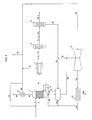
- FIG. 1 and FIG. 2 show the process flow of the method according to the invention each with and without a vacuum reservoir.
- FIG. 1 shows by way of example a reforming furnace ( 1 ) which is charged with a hydrocarbon-containing feed gas ( 2 ) and water vapor ( 3 ). This is heated with a hydrocarbon-containing fuel gas ( 4 ) and air ( 5 ). This gives synthesis gas, which is exemplified here as a mixture of hydrogen and carbon monoxide.
- synthesis gas which is exemplified here as a mixture of hydrogen and carbon monoxide.
- exhaust gases ( 4a ) are produced, which generate steam via a heat exchanger ( 6 ) ( FIG . 6a ).
- the exhaust gases are then delivered cooled as flue gases ( 6b ). If necessary, the steam can be returned directly to the starting gas ( 6c ) or blown off via a valve ( 6d ).
- the crude synthesis gas ( 3a ) obtained flows into a cooling device ( 7 ) where it is cooled and passed on to the carbon monoxide conversion device ( 8 ) ( 7a ). If the cooling device is a heat exchanger, steam can be obtained from the hot useful gas (FIG. 7b ).
- the carbon monoxide (CO) contained in the crude synthesis gas is converted to carbon dioxide (CO 2 ).
- This is passed into the pressure swing adsorption device ( 9 ). In this unit, the carbon dioxide is removed here by way of example, so that a purified synthesis gas ( 9a ) is obtained, which consists predominantly of hydrogen.
- the vacuum in the feed tank ( 11 ) is generated via a vacuum line ( 11a ) through an ejector ( 12 ) driven by the pressurized steam ( 6a ) from the steam generator ( 6 ).
- the ejector ( 12 ) generates, at least for the most part, the vacuum in the vacuum reservoir ( 11 ).
- the vacuum-desorbed gas ( 12a ) is obtained, which is passed into a condenser ( 13 ). This gives a condensate, which can be fed out ( 13a ), returned to the process for generating steam or can be returned to the water vapor as the starting gas ( 3 ) ( 13b ).
- the desorption gas obtained may be burnt by a torch line ( 13c ), put into the storage tank ( 10 ) for the heating gas ( 13d ) or fed directly into the heating gas ( 13e ). If the condensate is added to the starting gas ( 3 ), it is advantageously vaporized again via a reheater ( 13f ).
- FIG. 2 shows the process according to the invention, in which dispensed with a vacuum reservoir.
- the synthesis gas is produced in a reforming furnace ( 1 ) which is charged with a hydrocarbon-containing feed gas ( 2 ) and water vapor ( 3 ). This is heated with a hydrocarbon-containing fuel gas ( 4 ) and air ( 5 ). This gives synthesis gas, which is exemplified here as a mixture of hydrogen and carbon monoxide.
- exhaust gases ( 4a ) are produced, which generate steam via a heat exchanger ( 6 ) ( FIG . 6a ).
- the exhaust gases are then delivered cooled as flue gases ( 6b ).
- the steam can be returned directly to the starting gas ( 6c ) or blown off via a valve ( 6d ).
- the crude synthesis gas ( 3a ) obtained flows into a cooling device ( 7 ) where it is cooled and passed on to the carbon monoxide conversion device ( 8 ) ( 7a ). If the cooling device is a heat exchanger, steam can be obtained from the hot useful gas (FIG. 7b ).
- the carbon monoxide (CO) contained in the crude synthesis gas is converted to carbon dioxide (CO 2 ). This gives synthesis gas ( 8a ) with an excess of carbon dioxide. This is passed into the pressure swing adsorption device ( 9 ).
- the carbon dioxide is removed here by way of example, so that a purified synthesis gas ( 9a ) is obtained, which consists predominantly of hydrogen.
- a purified synthesis gas ( 9a ) is obtained, which consists predominantly of hydrogen.
- predominantly desorbed foreign gas ( 9b ) is obtained, which still contains adsorbed synthesis gas.
- This is desorbed and placed in the storage tank for the heating gas ( 10 ). From there, it can be fed into the heating gas for synthesis gas production ( 10a ) as desired.
- the desorption process is over the ejector ( 12 ) applied a vacuum and the desorption gas desorbed by vacuum through a vacuum line ( 9c ). If necessary, it can also be remixed with the desorption gas ( 10b ).
- the vacuum-desorbed gas ( 12a ) is obtained, which is passed into a condenser ( 13 ). This gives a condensate ( 13a ).
- the desorption gas obtained may be burnt by a torch line ( 13c ), put into the storage tank ( 10 ) for the heating gas ( 13d ) or fed directly into the heating gas ( 13e ).
Landscapes
- Chemical & Material Sciences (AREA)
- Organic Chemistry (AREA)
- Engineering & Computer Science (AREA)
- Chemical Kinetics & Catalysis (AREA)
- Combustion & Propulsion (AREA)
- Inorganic Chemistry (AREA)
- General Chemical & Material Sciences (AREA)
- Oil, Petroleum & Natural Gas (AREA)
- Analytical Chemistry (AREA)
- Health & Medical Sciences (AREA)
- General Health & Medical Sciences (AREA)
- Separation Of Gases By Adsorption (AREA)
- Hydrogen, Water And Hydrids (AREA)
Claims (16)
- Procédé de séparation de gaz étrangers (8a) contenus dans un gaz utile réducteur (3a) par adsorption modulée en pression (9), selon lequel- un gaz utile réducteur (3a), qui, en plus du composant réducteur, contient également un gaz étranger (8a) à adsorber, est fabriqué par un procédé approprié comprenant un procédé de chauffage, et- ce gaz utile (3a) est introduit pour la séparation de gaz étrangers adsorbables (8a) sous pression élevée dans une unité d'adsorption modulée en pression (9), qui retient les gaz étrangers à adsorber (8a) par un procédé d'adsorption, de manière à obtenir un gaz utile purifié (9a), et- les gaz étrangers adsorbés (8a) sont libérés par détente de l'unité d'adsorption modulée en pression (9) en mélange avec le gaz utile (9a), de manière à pouvoir être utilisés ultérieurement ou mis au rebus,- un vide (9c) est appliqué à l'unité d'adsorption modulée en pression (9) après la détente avec un éjecteur (12) pour la désorption, les gaz étrangers adsorbés restants (8a) étant ainsi soutirés de l'unité d'adsorption modulée en pression (9),
caractérisé en ce que- l'éjecteur (12) est actionné avec de la vapeur (6a), qui est générée par chauffage avec le gaz utile chaud (3a) et avec les gaz de fumée (4a) issus du procédé de chauffage pour la génération du gaz utile (3a). - Procédé selon la revendication 1, caractérisé en ce que la vapeur est condensée après l'éjecteur (12) par un dispositif approprié (13) et l'eau condensée (13b) est introduite dans le procédé de génération du gaz utile (3a) ou dans le générateur de vapeur (6) pour l'actionnement de l'éjecteur (12).
- Procédé selon l'une quelconque des revendications 1 ou 2, caractérisé en ce que- le gaz utile (3a) est un gaz de synthèse et le procédé de génération du gaz utile (3a) est un procédé de reformage à la vapeur,- un mélange de gaz naturel ou d'hydrocarbures légers et de vapeur d'eau est utilisé en tant que gaz de procédé (2) pour la génération du gaz de synthèse.
- Procédé selon la revendication 3, caractérisé en ce qu'une conversion (8) du monoxyde de carbone avec de la vapeur d'eau en dioxyde de carbone et en hydrogène a lieu après le procédé (1) de génération du gaz utile (3a) et avant l'adsorption modulée en pression (9).
- Procédé selon l'une quelconque des revendications 1 à 4, caractérisé en ce que les gaz étrangers (8a) désorbés dans l'unité d'adsorption modulée en pression (9) sont utilisés en tant que gaz de chauffage (4) pour la génération du gaz utile (3a) ou sont utilisés en mélange avec un gaz de chauffage frais en tant que gaz de combustion (4) pour la génération du gaz utile (3a), les gaz étrangers (8a) désorbés et soutirés par l'éjecteur (12) étant préparés directement par ajustement approprié de l'éjecteur (12) ou par des dispositifs appropriés à la même pression que celle à laquelle le gaz de chauffage (4) est introduit dans le procédé de combustion pour la génération du gaz utile (3a).
- Procédé selon l'une quelconque des revendications 1 à 5, caractérisé en ce que les gaz étrangers désorbés (8a) sont introduits avant le recyclage (13e) dans le procédé de chauffage pour la génération du gaz utile (3a) dans un contenant de stockage (10), qui peut être utilisé pour le stockage des gaz étrangers désorbés (8a) ou pour le stockage des gaz étrangers désorbés (8a) en mélange avec un gaz de chauffage.
- Procédé selon l'une quelconque des revendications 1 à 6, caractérisé en ce que- la sous-pression pour la désorption de l'unité d'adsorption modulée en pression (9) et les gaz étrangers désorbés (8a) sont stockés dans un contenant de stockage (11),- la sous-pression générée par l'éjecteur (12) peut être augmentée par un dispositif générant un vide supplémentaire à un emplacement quelconque dans le flux de procédé ou la sous-pression dans le contenant de stockage (11) peut être augmentée.
- Procédé selon l'une quelconque des revendications 1 à 7, caractérisé en ce que l'éjecteur (12) est actionné temporairement ou partiellement ou temporairement et partiellement avec un gaz auxiliaire ou le gaz de synthèse ou un mélange des deux gaz, le gaz auxiliaire consistant en totalité ou en partie en de la vapeur issue d'une source externe à l'unité.
- Dispositif pour la séparation de gaz étrangers (8a) contenus dans un gaz utile réducteur (3a) par adsorption modulée en pression (9), qui comprend- une partie d'unité comprenant un dispositif de chauffage pour la génération du gaz utile (3a),- une partie d'unité comprenant une adsorption modulée en pression (9) pour la séparation de gaz étrangers (8a) suivant la partie d'unité pour la génération du gaz utile (3a), et- un vide pouvant être appliqué à la partie d'unité pour l'adsorption modulée en pression (9) par un éjecteur (12), qui est approprié pour la génération d'une sous-pression, pour la désorption complète, caractérisé en ce que- un générateur de vapeur (7) se trouve après le dispositif de chauffage ou la partie d'unité (1) pour la génération du gaz utile (3a), ledit générateur utilisant le gaz de fumée chaud (4a) et le gaz utile chaud (3a) issu du procédé de chauffage pour la génération de vapeur chaude, et- la vapeur provenant du générateur de vapeur est utilisée pour l'actionnement de l'éjecteur (12).
- Dispositif selon la revendication 9, caractérisé en ce qu'un dispositif (13) se trouve au niveau de la conduite de sortie du côté de l'actionnement de l'éjecteur (12), avec lequel la vapeur utilisée pour l'actionnement de l'éjecteur (12) peut être condensée, des canalisations étant connectées au dispositif de condensation (13), avec lesquelles le condensat peut être recyclé dans le procédé de génération du gaz utile en tant que composant de départ (13b).
- Dispositif selon l'une quelconque des revendications 9 ou 10, caractérisé en ce qu'un dispositif (8) pour la conversion de monoxyde de carbone se trouve après le dispositif (1) pour la génération du gaz utile (3a), dans lequel le monoxyde de carbone contenu dans le gaz utile réducteur (3a) est transformé en un mélange (8a) de dioxyde de carbone et d'hydrogène.
- Dispositif selon la revendication 11, caractérisé en ce qu'un dispositif de refroidissement (7) pour le gaz utile (3a) se trouve entre l'unité de génération (1) pour la génération du gaz utile (3a) et le dispositif (8) pour la conversion du monoxyde de carbone, le dispositif de refroidissement (7) pour le gaz utile (3a) consistant en un générateur de vapeur.
- Dispositif selon l'une quelconque des revendications 11 à 12, caractérisé en ce qu'un dispositif de refroidissement pour le gaz utile (3a) se trouve après le dispositif (8) pour la conversion du monoxyde de carbone, le dispositif de refroidissement pour le gaz utile (3a) après le dispositif de conversion du monoxyde de carbone consistant en un générateur de vapeur.
- Dispositif selon l'une quelconque des revendications 9 à 13, caractérisé en ce qu'un contenant de stockage (11) pour le vide généré se trouve après l'unité d'adsorption modulée en pression (9) du côté de l'aspiration de l'éjecteur (12).
- Dispositif selon l'une quelconque des revendications 9 à 14, caractérisé en ce qu'un contenant de stockage (10) pour le gaz de chauffage se trouve après l'unité d'adsorption modulée en pression (9), ledit contenant pouvant également être alimenté avec les gaz étrangers désorbés (8a) par des canalisations (13d) par le côté de sortie de l'éjecteur (12) ou par un condensateur (13) connecté en aval de l'éjecteur (12).
- Dispositif selon l'une quelconque des revendications 9 à 15, caractérisé en ce qu'un dispositif se trouve du côté de l'aspiration après l'éjecteur (12), ledit dispositif générant un vide de manière à ce que le vide généré par l'éjecteur (12) puisse être renforcé avec celui-ci.
Priority Applications (1)
| Application Number | Priority Date | Filing Date | Title |
|---|---|---|---|
| PL09716244T PL2249948T3 (pl) | 2008-03-05 | 2009-02-17 | Sposób i instalacja do wytrącania gazów obcych z redukującego gazu użytecznego z zastosowaniem parowej adsorpcji zmiennociśnieniowej |
Applications Claiming Priority (2)
| Application Number | Priority Date | Filing Date | Title |
|---|---|---|---|
| DE102008012735A DE102008012735B4 (de) | 2008-03-05 | 2008-03-05 | Verfahren und Vorrichtung zur Abscheidung von Fremdgasen aus einem reduzierenden Nutzgas durch dampfbetriebene Druckwechseladsorption |
| PCT/EP2009/001092 WO2009109290A1 (fr) | 2008-03-05 | 2009-02-17 | Procédé et dispositif de séparation de gaz étrangers contenus dans un gaz utile réducteur par adsorption modulée en pression à vapeur |
Publications (2)
| Publication Number | Publication Date |
|---|---|
| EP2249948A1 EP2249948A1 (fr) | 2010-11-17 |
| EP2249948B1 true EP2249948B1 (fr) | 2015-06-24 |
Family
ID=40873340
Family Applications (1)
| Application Number | Title | Priority Date | Filing Date |
|---|---|---|---|
| EP09716244.0A Not-in-force EP2249948B1 (fr) | 2008-03-05 | 2009-02-17 | Procédé et dispositif de séparation de gaz étrangers contenus dans un gaz utile réducteur par adsorption modulée en pression à vapeur |
Country Status (14)
| Country | Link |
|---|---|
| US (1) | US8361198B2 (fr) |
| EP (1) | EP2249948B1 (fr) |
| CN (1) | CN101959576A (fr) |
| BR (1) | BRPI0909815A2 (fr) |
| CA (1) | CA2716781A1 (fr) |
| CO (1) | CO6300851A2 (fr) |
| DE (1) | DE102008012735B4 (fr) |
| EA (1) | EA017672B1 (fr) |
| HU (1) | HUE026169T2 (fr) |
| MX (1) | MX2010009719A (fr) |
| MY (1) | MY152106A (fr) |
| PL (1) | PL2249948T3 (fr) |
| WO (1) | WO2009109290A1 (fr) |
| ZA (1) | ZA201005950B (fr) |
Families Citing this family (13)
| Publication number | Priority date | Publication date | Assignee | Title |
|---|---|---|---|---|
| AT507954B1 (de) * | 2009-02-20 | 2010-12-15 | Siemens Vai Metals Tech Gmbh | Verfahren und vorrichtung zum abscheiden eines gasförmigen bestandteils |
| DE102009042520A1 (de) * | 2009-09-22 | 2011-03-24 | Uhde Gmbh | Verfahren zum Betrieb einer Koksofenanordnung |
| JP5638262B2 (ja) * | 2010-02-23 | 2014-12-10 | 三菱重工業株式会社 | Co2回収装置およびco2回収方法 |
| CN101954233B (zh) * | 2010-09-26 | 2013-09-11 | 西安建筑科技大学 | 柠檬酸盐溶液吸收二氧化硫的吸收富液的解吸方法及装置 |
| JP6035553B2 (ja) * | 2011-03-01 | 2016-11-30 | エクソンモービル アップストリーム リサーチ カンパニー | スイング吸着により炭化水素流から汚染物質を除去する方法並びに関連装置及びシステム |
| EP2938425A4 (fr) * | 2012-12-31 | 2016-11-23 | Inventys Thermal Technologies Inc | Système et procédé de séparation intégrée de gaz carbonique à partir de gaz de combustion |
| DK3426981T3 (da) * | 2016-03-31 | 2022-06-20 | Inventys Thermal Tech Inc | Forbrændingssystem, der inkorporerer gasseparation ved temperatursvingningsadsorption |
| CN106925074A (zh) * | 2017-03-20 | 2017-07-07 | 西安纳瑞工控科技有限公司 | 一种尾气净化及资源化回收工艺及其装置 |
| DE102017004326A1 (de) * | 2017-05-04 | 2018-11-08 | Linde Aktiengesellschaft | Verbesserte Verwendung des Restgases einer Druckwechseladsorptionsanlage |
| CN107983081B (zh) * | 2017-12-27 | 2024-04-30 | 江苏刚正薄板科技有限公司 | 一种钢板生产过程中产生的无组织废气吸附解吸装置 |
| CN109939535A (zh) * | 2018-12-17 | 2019-06-28 | 上海伊尔庚环境工程有限公司 | 一种二甲苯有机废气治理回收的方法及系统 |
| WO2024059964A1 (fr) * | 2022-09-19 | 2024-03-28 | 重庆冲能动力机械有限公司 | Système de séparation de gaz par adsorption modulée en pression entraîné par des turbines, et procédé de séparation |
| KR102795475B1 (ko) * | 2023-07-18 | 2025-04-11 | 더 유니버시티 코트 오브 더 유니버시티 오브 에딘버그 | 가스 분리 방법 및 시스템 |
Family Cites Families (12)
| Publication number | Priority date | Publication date | Assignee | Title |
|---|---|---|---|---|
| US3141748A (en) * | 1961-11-20 | 1964-07-21 | Exxon Research Engineering Co | Hydrogen purification process |
| DE2906057A1 (de) | 1979-02-16 | 1980-08-28 | Linde Ag | Druckwechseladsorptionsverfahren zur zerlegung oder reinigung von gasgemischen |
| US5203888A (en) * | 1990-11-23 | 1993-04-20 | Uop | Pressure swing adsorption process with multiple desorption steps |
| GB9703959D0 (en) | 1997-02-26 | 1997-04-16 | Boc Group Plc | Air separation |
| DE19829389C1 (de) | 1998-07-01 | 2000-01-05 | Krupp Uhde Gmbh | Verfahren zur Rückgewinnung von Gasen |
| DE19951191C2 (de) | 1999-10-22 | 2001-08-23 | Thyssen Krupp Encoke Gmbh | Verfahren und Vorrichtung zur Ableitung von heissen Rohgasen, die bei einer Verkokung in den Ofenkammern einer Koksofenbatterie entstehen |
| DE19955676B4 (de) * | 1999-11-19 | 2004-06-03 | Uhde Gmbh | Verfahren zur Herstellung von Synthesegas in Verbindung mit einer Druckwechsel-Adsorptionsanlage |
| US6322612B1 (en) * | 1999-12-23 | 2001-11-27 | Air Products And Chemicals, Inc. | PSA process for removal of bulk carbon dioxide from a wet high-temperature gas |
| US7285350B2 (en) * | 2002-09-27 | 2007-10-23 | Questair Technologies Inc. | Enhanced solid oxide fuel cell systems |
| DE102005021500A1 (de) | 2005-05-10 | 2006-11-16 | Uhde Gmbh | Verfahren zur Aufheizung eines Dampf-/Erdgasgemisches im Bereich eines Gassammelrohres nach einem Primärreformer |
| JP3956993B1 (ja) * | 2006-01-30 | 2007-08-08 | 石川島播磨重工業株式会社 | ガスタービンを用いた揮発性有機化合物処理方法及び揮発性有機化合物処理システム |
| DE102006032104A1 (de) | 2006-07-11 | 2008-01-24 | Linde Ag | Verfahren zur Erzeugung von Wasserstoff und Wasserstoff enthaltenden Gasgemischen |
-
2008
- 2008-03-05 DE DE102008012735A patent/DE102008012735B4/de not_active Expired - Fee Related
-
2009
- 2009-02-17 MY MYPI20104029 patent/MY152106A/en unknown
- 2009-02-17 EP EP09716244.0A patent/EP2249948B1/fr not_active Not-in-force
- 2009-02-17 EA EA201071030A patent/EA017672B1/ru not_active IP Right Cessation
- 2009-02-17 US US12/736,046 patent/US8361198B2/en not_active Expired - Fee Related
- 2009-02-17 CA CA2716781A patent/CA2716781A1/fr not_active Abandoned
- 2009-02-17 WO PCT/EP2009/001092 patent/WO2009109290A1/fr not_active Ceased
- 2009-02-17 HU HUE09716244A patent/HUE026169T2/en unknown
- 2009-02-17 MX MX2010009719A patent/MX2010009719A/es active IP Right Grant
- 2009-02-17 PL PL09716244T patent/PL2249948T3/pl unknown
- 2009-02-17 CN CN2009801077440A patent/CN101959576A/zh active Pending
- 2009-02-17 BR BRPI0909815-1A patent/BRPI0909815A2/pt not_active IP Right Cessation
-
2010
- 2010-08-20 ZA ZA2010/05950A patent/ZA201005950B/en unknown
- 2010-10-05 CO CO10123518A patent/CO6300851A2/es active IP Right Grant
Also Published As
| Publication number | Publication date |
|---|---|
| MY152106A (en) | 2014-08-15 |
| WO2009109290A1 (fr) | 2009-09-11 |
| US8361198B2 (en) | 2013-01-29 |
| PL2249948T3 (pl) | 2016-01-29 |
| DE102008012735A1 (de) | 2009-09-10 |
| EP2249948A1 (fr) | 2010-11-17 |
| EA201071030A1 (ru) | 2011-02-28 |
| DE102008012735B4 (de) | 2013-05-08 |
| CA2716781A1 (fr) | 2009-09-11 |
| ZA201005950B (en) | 2011-07-27 |
| HUE026169T2 (en) | 2016-05-30 |
| MX2010009719A (es) | 2010-09-30 |
| BRPI0909815A2 (pt) | 2019-03-06 |
| EA017672B1 (ru) | 2013-02-28 |
| CN101959576A (zh) | 2011-01-26 |
| CO6300851A2 (es) | 2011-07-21 |
| US20110061529A1 (en) | 2011-03-17 |
Similar Documents
| Publication | Publication Date | Title |
|---|---|---|
| EP2249948B1 (fr) | Procédé et dispositif de séparation de gaz étrangers contenus dans un gaz utile réducteur par adsorption modulée en pression à vapeur | |
| EP4098610A1 (fr) | Procédé et installation de production d'hydrogène pur par vaporeformage à émission réduite de dioxyde de carbone | |
| CH697901B1 (de) | Polygenerationsanordnung. | |
| DE102005051952B3 (de) | Verfahren zur Herstellung von Methan und flüssigem Kohlendioxid aus Raffinerie- und/oder Biogas | |
| US11760632B2 (en) | Regeneration schemes for a two-stage adsorption process for Claus tail gas treatment | |
| CN107754555B (zh) | 一种变压吸附分离臭氧与氧气的方法及装置 | |
| EP3176152B1 (fr) | Procede de fabrication d'uree | |
| EP2485980B1 (fr) | Procédé permettant de faire fonctionner un processus de centrale igcc à séparation de co2 intégrée | |
| EP1101731B1 (fr) | Procédé pour la production de gaz de synthèse combiné avec un dispositif d'adsorption à pression alternée | |
| EP1961697A1 (fr) | Production de produits à partir de gaz d'échappement de raffinerie | |
| EP2481705A1 (fr) | Procédé et dispositif de recyclage matériel et/ou énergétique de résidus biogènes | |
| WO2009118227A1 (fr) | Procédé et dispositif de séparation de dioxyde de carbone d'un effluent gazeux d'une centrale électrique à combustible fossile | |
| CN213101492U (zh) | 从石化排放尾气中同时回收氢气和甲烷气的装置 | |
| EP1519781B1 (fr) | Dispositif de desorption de dioxyde de carbone a partir de methanol | |
| DE102016103321B4 (de) | Vorrichtung und Verfahren zur Dampfreformierung | |
| WO2024078713A1 (fr) | Production de mélanges gazeux d'hydrogène et de dioxyde de carbone | |
| EP3674261B1 (fr) | Procédé de synthèse d'un composé contenant de l'hydrogène | |
| EP4098609A1 (fr) | Procédé et installation de production d'hydrogène pur par vaporeformage à émission réduite de dioxyde de carbone | |
| EP0203323B1 (fr) | Procédé et dispositif pour purifier et enrichir des gaz de décharge | |
| CN114073882B (zh) | 从石化排放尾气中同时回收氢气和甲烷气等多种气体的工艺技术和装置 | |
| DE10305806A1 (de) | Brennstoffzelle mit integrierter Vergasung oder Reformierung | |
| DE102024121674A1 (de) | Verfahren und Vorrichtung zum Herstellen eines methanhaltigen Produktgases aus einem kohlendioxidhaltigen Eingangsgas und Wasserstoff | |
| US20090065108A1 (en) | Integrated Reformer and Batch Annealing Processes and Apparatus Therefor | |
| WO2025088183A1 (fr) | Procédé et installation de production d'ammoniac avec reformeur autothermique | |
| CA3241116A1 (fr) | Traitement de gaz residuaire de claus a base d'adsorption |
Legal Events
| Date | Code | Title | Description |
|---|---|---|---|
| PUAI | Public reference made under article 153(3) epc to a published international application that has entered the european phase |
Free format text: ORIGINAL CODE: 0009012 |
|
| 17P | Request for examination filed |
Effective date: 20100830 |
|
| AK | Designated contracting states |
Kind code of ref document: A1 Designated state(s): AT BE BG CH CY CZ DE DK EE ES FI FR GB GR HR HU IE IS IT LI LT LU LV MC MK MT NL NO PL PT RO SE SI SK TR |
|
| AX | Request for extension of the european patent |
Extension state: AL BA RS |
|
| DAX | Request for extension of the european patent (deleted) | ||
| RAP1 | Party data changed (applicant data changed or rights of an application transferred) |
Owner name: THYSSENKRUPP UHDE GMBH |
|
| 17Q | First examination report despatched |
Effective date: 20140219 |
|
| RAP1 | Party data changed (applicant data changed or rights of an application transferred) |
Owner name: THYSSENKRUPP INDUSTRIAL SOLUTIONS AG |
|
| GRAP | Despatch of communication of intention to grant a patent |
Free format text: ORIGINAL CODE: EPIDOSNIGR1 |
|
| RIC1 | Information provided on ipc code assigned before grant |
Ipc: B01D 53/047 20060101AFI20150209BHEP Ipc: C01B 3/56 20060101ALI20150209BHEP Ipc: C01B 3/34 20060101ALI20150209BHEP |
|
| INTG | Intention to grant announced |
Effective date: 20150317 |
|
| GRAS | Grant fee paid |
Free format text: ORIGINAL CODE: EPIDOSNIGR3 |
|
| GRAA | (expected) grant |
Free format text: ORIGINAL CODE: 0009210 |
|
| AK | Designated contracting states |
Kind code of ref document: B1 Designated state(s): AT BE BG CH CY CZ DE DK EE ES FI FR GB GR HR HU IE IS IT LI LT LU LV MC MK MT NL NO PL PT RO SE SI SK TR |
|
| REG | Reference to a national code |
Ref country code: GB Ref legal event code: FG4D Free format text: NOT ENGLISH |
|
| REG | Reference to a national code |
Ref country code: CH Ref legal event code: EP |
|
| REG | Reference to a national code |
Ref country code: AT Ref legal event code: REF Ref document number: 732659 Country of ref document: AT Kind code of ref document: T Effective date: 20150715 |
|
| REG | Reference to a national code |
Ref country code: IE Ref legal event code: FG4D Free format text: LANGUAGE OF EP DOCUMENT: GERMAN |
|
| REG | Reference to a national code |
Ref country code: DE Ref legal event code: R096 Ref document number: 502009011177 Country of ref document: DE |
|
| REG | Reference to a national code |
Ref country code: RO Ref legal event code: EPE |
|
| PG25 | Lapsed in a contracting state [announced via postgrant information from national office to epo] |
Ref country code: LT Free format text: LAPSE BECAUSE OF FAILURE TO SUBMIT A TRANSLATION OF THE DESCRIPTION OR TO PAY THE FEE WITHIN THE PRESCRIBED TIME-LIMIT Effective date: 20150624 Ref country code: HR Free format text: LAPSE BECAUSE OF FAILURE TO SUBMIT A TRANSLATION OF THE DESCRIPTION OR TO PAY THE FEE WITHIN THE PRESCRIBED TIME-LIMIT Effective date: 20150624 |
|
| REG | Reference to a national code |
Ref country code: NL Ref legal event code: FP |
|
| REG | Reference to a national code |
Ref country code: NO Ref legal event code: T2 Effective date: 20150624 |
|
| REG | Reference to a national code |
Ref country code: LT Ref legal event code: MG4D |
|
| PG25 | Lapsed in a contracting state [announced via postgrant information from national office to epo] |
Ref country code: GR Free format text: LAPSE BECAUSE OF FAILURE TO SUBMIT A TRANSLATION OF THE DESCRIPTION OR TO PAY THE FEE WITHIN THE PRESCRIBED TIME-LIMIT Effective date: 20150925 Ref country code: LV Free format text: LAPSE BECAUSE OF FAILURE TO SUBMIT A TRANSLATION OF THE DESCRIPTION OR TO PAY THE FEE WITHIN THE PRESCRIBED TIME-LIMIT Effective date: 20150624 Ref country code: BG Free format text: LAPSE BECAUSE OF FAILURE TO SUBMIT A TRANSLATION OF THE DESCRIPTION OR TO PAY THE FEE WITHIN THE PRESCRIBED TIME-LIMIT Effective date: 20150924 |
|
| REG | Reference to a national code |
Ref country code: EE Ref legal event code: FG4A Ref document number: E011245 Country of ref document: EE Effective date: 20150918 |
|
| PG25 | Lapsed in a contracting state [announced via postgrant information from national office to epo] |
Ref country code: IS Free format text: LAPSE BECAUSE OF FAILURE TO SUBMIT A TRANSLATION OF THE DESCRIPTION OR TO PAY THE FEE WITHIN THE PRESCRIBED TIME-LIMIT Effective date: 20151024 Ref country code: PT Free format text: LAPSE BECAUSE OF FAILURE TO SUBMIT A TRANSLATION OF THE DESCRIPTION OR TO PAY THE FEE WITHIN THE PRESCRIBED TIME-LIMIT Effective date: 20151026 Ref country code: ES Free format text: LAPSE BECAUSE OF FAILURE TO SUBMIT A TRANSLATION OF THE DESCRIPTION OR TO PAY THE FEE WITHIN THE PRESCRIBED TIME-LIMIT Effective date: 20150624 Ref country code: SK Free format text: LAPSE BECAUSE OF FAILURE TO SUBMIT A TRANSLATION OF THE DESCRIPTION OR TO PAY THE FEE WITHIN THE PRESCRIBED TIME-LIMIT Effective date: 20150624 Ref country code: CZ Free format text: LAPSE BECAUSE OF FAILURE TO SUBMIT A TRANSLATION OF THE DESCRIPTION OR TO PAY THE FEE WITHIN THE PRESCRIBED TIME-LIMIT Effective date: 20150624 |
|
| REG | Reference to a national code |
Ref country code: DE Ref legal event code: R097 Ref document number: 502009011177 Country of ref document: DE |
|
| PG25 | Lapsed in a contracting state [announced via postgrant information from national office to epo] |
Ref country code: DK Free format text: LAPSE BECAUSE OF FAILURE TO SUBMIT A TRANSLATION OF THE DESCRIPTION OR TO PAY THE FEE WITHIN THE PRESCRIBED TIME-LIMIT Effective date: 20150624 |
|
| PGFP | Annual fee paid to national office [announced via postgrant information from national office to epo] |
Ref country code: TR Payment date: 20160126 Year of fee payment: 8 Ref country code: DE Payment date: 20160218 Year of fee payment: 8 Ref country code: IT Payment date: 20160223 Year of fee payment: 8 Ref country code: NO Payment date: 20160222 Year of fee payment: 8 Ref country code: EE Payment date: 20160212 Year of fee payment: 8 |
|
| PLBE | No opposition filed within time limit |
Free format text: ORIGINAL CODE: 0009261 |
|
| STAA | Information on the status of an ep patent application or granted ep patent |
Free format text: STATUS: NO OPPOSITION FILED WITHIN TIME LIMIT |
|
| REG | Reference to a national code |
Ref country code: HU Ref legal event code: AG4A Ref document number: E026169 Country of ref document: HU |
|
| PGFP | Annual fee paid to national office [announced via postgrant information from national office to epo] |
Ref country code: NL Payment date: 20160217 Year of fee payment: 8 Ref country code: FI Payment date: 20160211 Year of fee payment: 8 Ref country code: RO Payment date: 20160126 Year of fee payment: 8 Ref country code: AT Payment date: 20160218 Year of fee payment: 8 Ref country code: HU Payment date: 20160216 Year of fee payment: 8 Ref country code: PL Payment date: 20160128 Year of fee payment: 8 Ref country code: BE Payment date: 20160217 Year of fee payment: 8 |
|
| 26N | No opposition filed |
Effective date: 20160329 |
|
| PG25 | Lapsed in a contracting state [announced via postgrant information from national office to epo] |
Ref country code: SI Free format text: LAPSE BECAUSE OF FAILURE TO SUBMIT A TRANSLATION OF THE DESCRIPTION OR TO PAY THE FEE WITHIN THE PRESCRIBED TIME-LIMIT Effective date: 20150624 |
|
| PG25 | Lapsed in a contracting state [announced via postgrant information from national office to epo] |
Ref country code: MC Free format text: LAPSE BECAUSE OF FAILURE TO SUBMIT A TRANSLATION OF THE DESCRIPTION OR TO PAY THE FEE WITHIN THE PRESCRIBED TIME-LIMIT Effective date: 20150624 Ref country code: LU Free format text: LAPSE BECAUSE OF FAILURE TO SUBMIT A TRANSLATION OF THE DESCRIPTION OR TO PAY THE FEE WITHIN THE PRESCRIBED TIME-LIMIT Effective date: 20160217 |
|
| REG | Reference to a national code |
Ref country code: CH Ref legal event code: PL |
|
| GBPC | Gb: european patent ceased through non-payment of renewal fee |
Effective date: 20160217 |
|
| PG25 | Lapsed in a contracting state [announced via postgrant information from national office to epo] |
Ref country code: CH Free format text: LAPSE BECAUSE OF NON-PAYMENT OF DUE FEES Effective date: 20160229 Ref country code: LI Free format text: LAPSE BECAUSE OF NON-PAYMENT OF DUE FEES Effective date: 20160229 |
|
| REG | Reference to a national code |
Ref country code: FR Ref legal event code: ST Effective date: 20161028 |
|
| REG | Reference to a national code |
Ref country code: IE Ref legal event code: MM4A |
|
| PG25 | Lapsed in a contracting state [announced via postgrant information from national office to epo] |
Ref country code: GB Free format text: LAPSE BECAUSE OF NON-PAYMENT OF DUE FEES Effective date: 20160217 Ref country code: IE Free format text: LAPSE BECAUSE OF NON-PAYMENT OF DUE FEES Effective date: 20160217 Ref country code: FR Free format text: LAPSE BECAUSE OF NON-PAYMENT OF DUE FEES Effective date: 20160229 |
|
| PG25 | Lapsed in a contracting state [announced via postgrant information from national office to epo] |
Ref country code: BE Free format text: LAPSE BECAUSE OF NON-PAYMENT OF DUE FEES Effective date: 20170228 |
|
| PG25 | Lapsed in a contracting state [announced via postgrant information from national office to epo] |
Ref country code: SE Free format text: LAPSE BECAUSE OF FAILURE TO SUBMIT A TRANSLATION OF THE DESCRIPTION OR TO PAY THE FEE WITHIN THE PRESCRIBED TIME-LIMIT Effective date: 20150624 |
|
| PG25 | Lapsed in a contracting state [announced via postgrant information from national office to epo] |
Ref country code: MT Free format text: LAPSE BECAUSE OF FAILURE TO SUBMIT A TRANSLATION OF THE DESCRIPTION OR TO PAY THE FEE WITHIN THE PRESCRIBED TIME-LIMIT Effective date: 20150624 |
|
| REG | Reference to a national code |
Ref country code: DE Ref legal event code: R119 Ref document number: 502009011177 Country of ref document: DE |
|
| REG | Reference to a national code |
Ref country code: EE Ref legal event code: MM4A Ref document number: E011245 Country of ref document: EE Effective date: 20170228 |
|
| REG | Reference to a national code |
Ref country code: NO Ref legal event code: MMEP |
|
| REG | Reference to a national code |
Ref country code: NL Ref legal event code: MM Effective date: 20170301 |
|
| REG | Reference to a national code |
Ref country code: AT Ref legal event code: MM01 Ref document number: 732659 Country of ref document: AT Kind code of ref document: T Effective date: 20170217 |
|
| PG25 | Lapsed in a contracting state [announced via postgrant information from national office to epo] |
Ref country code: AT Free format text: LAPSE BECAUSE OF NON-PAYMENT OF DUE FEES Effective date: 20170217 Ref country code: EE Free format text: LAPSE BECAUSE OF NON-PAYMENT OF DUE FEES Effective date: 20170228 Ref country code: NO Free format text: LAPSE BECAUSE OF NON-PAYMENT OF DUE FEES Effective date: 20170228 Ref country code: FI Free format text: LAPSE BECAUSE OF NON-PAYMENT OF DUE FEES Effective date: 20170217 |
|
| PG25 | Lapsed in a contracting state [announced via postgrant information from national office to epo] |
Ref country code: HU Free format text: LAPSE BECAUSE OF NON-PAYMENT OF DUE FEES Effective date: 20170218 Ref country code: NL Free format text: LAPSE BECAUSE OF NON-PAYMENT OF DUE FEES Effective date: 20170301 |
|
| PG25 | Lapsed in a contracting state [announced via postgrant information from national office to epo] |
Ref country code: DE Free format text: LAPSE BECAUSE OF NON-PAYMENT OF DUE FEES Effective date: 20170901 |
|
| REG | Reference to a national code |
Ref country code: BE Ref legal event code: MM Effective date: 20170228 |
|
| PG25 | Lapsed in a contracting state [announced via postgrant information from national office to epo] |
Ref country code: IT Free format text: LAPSE BECAUSE OF NON-PAYMENT OF DUE FEES Effective date: 20170217 |
|
| PG25 | Lapsed in a contracting state [announced via postgrant information from national office to epo] |
Ref country code: CY Free format text: LAPSE BECAUSE OF FAILURE TO SUBMIT A TRANSLATION OF THE DESCRIPTION OR TO PAY THE FEE WITHIN THE PRESCRIBED TIME-LIMIT Effective date: 20150624 |
|
| PG25 | Lapsed in a contracting state [announced via postgrant information from national office to epo] |
Ref country code: MK Free format text: LAPSE BECAUSE OF FAILURE TO SUBMIT A TRANSLATION OF THE DESCRIPTION OR TO PAY THE FEE WITHIN THE PRESCRIBED TIME-LIMIT Effective date: 20150624 |
|
| PG25 | Lapsed in a contracting state [announced via postgrant information from national office to epo] |
Ref country code: PL Free format text: LAPSE BECAUSE OF NON-PAYMENT OF DUE FEES Effective date: 20170217 |
|
| PG25 | Lapsed in a contracting state [announced via postgrant information from national office to epo] |
Ref country code: RO Free format text: LAPSE BECAUSE OF NON-PAYMENT OF DUE FEES Effective date: 20170217 |
|
| PG25 | Lapsed in a contracting state [announced via postgrant information from national office to epo] |
Ref country code: TR Free format text: LAPSE BECAUSE OF NON-PAYMENT OF DUE FEES Effective date: 20170217 |