EP2249994B1 - Unité de production de pression hydraulique pour une visseuse mécanique - Google Patents
Unité de production de pression hydraulique pour une visseuse mécanique Download PDFInfo
- Publication number
- EP2249994B1 EP2249994B1 EP09719703A EP09719703A EP2249994B1 EP 2249994 B1 EP2249994 B1 EP 2249994B1 EP 09719703 A EP09719703 A EP 09719703A EP 09719703 A EP09719703 A EP 09719703A EP 2249994 B1 EP2249994 B1 EP 2249994B1
- Authority
- EP
- European Patent Office
- Prior art keywords
- pressure
- supply unit
- supply
- hydraulic pressure
- connector
- Prior art date
- Legal status (The legal status is an assumption and is not a legal conclusion. Google has not performed a legal analysis and makes no representation as to the accuracy of the status listed.)
- Active
Links
Images

Classifications
-
- B—PERFORMING OPERATIONS; TRANSPORTING
- B25—HAND TOOLS; PORTABLE POWER-DRIVEN TOOLS; MANIPULATORS
- B25B—TOOLS OR BENCH DEVICES NOT OTHERWISE PROVIDED FOR, FOR FASTENING, CONNECTING, DISENGAGING, OR HOLDING
- B25B21/00—Portable power-driven screw or nut setting or loosening tools; Attachments for drilling apparatus serving the same purpose
- B25B21/004—Portable power-driven screw or nut setting or loosening tools; Attachments for drilling apparatus serving the same purpose of the ratchet type
- B25B21/005—Portable power-driven screw or nut setting or loosening tools; Attachments for drilling apparatus serving the same purpose of the ratchet type driven by a radially acting hydraulic or pneumatic piston
-
- B—PERFORMING OPERATIONS; TRANSPORTING
- B25—HAND TOOLS; PORTABLE POWER-DRIVEN TOOLS; MANIPULATORS
- B25B—TOOLS OR BENCH DEVICES NOT OTHERWISE PROVIDED FOR, FOR FASTENING, CONNECTING, DISENGAGING, OR HOLDING
- B25B29/00—Accessories
- B25B29/02—Bolt tensioners
-
- F—MECHANICAL ENGINEERING; LIGHTING; HEATING; WEAPONS; BLASTING
- F15—FLUID-PRESSURE ACTUATORS; HYDRAULICS OR PNEUMATICS IN GENERAL
- F15B—SYSTEMS ACTING BY MEANS OF FLUIDS IN GENERAL; FLUID-PRESSURE ACTUATORS, e.g. SERVOMOTORS; DETAILS OF FLUID-PRESSURE SYSTEMS, NOT OTHERWISE PROVIDED FOR
- F15B11/00—Servomotor systems without provision for follow-up action; Circuits therefor
- F15B11/02—Systems essentially incorporating special features for controlling the speed or actuating force of an output member
- F15B11/028—Systems essentially incorporating special features for controlling the speed or actuating force of an output member for controlling the actuating force
- F15B11/032—Systems essentially incorporating special features for controlling the speed or actuating force of an output member for controlling the actuating force by means of fluid-pressure converters
-
- F—MECHANICAL ENGINEERING; LIGHTING; HEATING; WEAPONS; BLASTING
- F15—FLUID-PRESSURE ACTUATORS; HYDRAULICS OR PNEUMATICS IN GENERAL
- F15B—SYSTEMS ACTING BY MEANS OF FLUIDS IN GENERAL; FLUID-PRESSURE ACTUATORS, e.g. SERVOMOTORS; DETAILS OF FLUID-PRESSURE SYSTEMS, NOT OTHERWISE PROVIDED FOR
- F15B2211/00—Circuits for servomotor systems
- F15B2211/20—Fluid pressure source, e.g. accumulator or variable axial piston pump
- F15B2211/21—Systems with pressure sources other than pumps, e.g. with a pyrotechnical charge
-
- F—MECHANICAL ENGINEERING; LIGHTING; HEATING; WEAPONS; BLASTING
- F15—FLUID-PRESSURE ACTUATORS; HYDRAULICS OR PNEUMATICS IN GENERAL
- F15B—SYSTEMS ACTING BY MEANS OF FLUIDS IN GENERAL; FLUID-PRESSURE ACTUATORS, e.g. SERVOMOTORS; DETAILS OF FLUID-PRESSURE SYSTEMS, NOT OTHERWISE PROVIDED FOR
- F15B2211/00—Circuits for servomotor systems
- F15B2211/20—Fluid pressure source, e.g. accumulator or variable axial piston pump
- F15B2211/25—Pressure control functions
- F15B2211/251—High pressure control
-
- F—MECHANICAL ENGINEERING; LIGHTING; HEATING; WEAPONS; BLASTING
- F15—FLUID-PRESSURE ACTUATORS; HYDRAULICS OR PNEUMATICS IN GENERAL
- F15B—SYSTEMS ACTING BY MEANS OF FLUIDS IN GENERAL; FLUID-PRESSURE ACTUATORS, e.g. SERVOMOTORS; DETAILS OF FLUID-PRESSURE SYSTEMS, NOT OTHERWISE PROVIDED FOR
- F15B2211/00—Circuits for servomotor systems
- F15B2211/30—Directional control
- F15B2211/305—Directional control characterised by the type of valves
- F15B2211/3052—Shuttle valves
-
- F—MECHANICAL ENGINEERING; LIGHTING; HEATING; WEAPONS; BLASTING
- F15—FLUID-PRESSURE ACTUATORS; HYDRAULICS OR PNEUMATICS IN GENERAL
- F15B—SYSTEMS ACTING BY MEANS OF FLUIDS IN GENERAL; FLUID-PRESSURE ACTUATORS, e.g. SERVOMOTORS; DETAILS OF FLUID-PRESSURE SYSTEMS, NOT OTHERWISE PROVIDED FOR
- F15B2211/00—Circuits for servomotor systems
- F15B2211/30—Directional control
- F15B2211/305—Directional control characterised by the type of valves
- F15B2211/30525—Directional control valves, e.g. 4/3-directional control valve
-
- F—MECHANICAL ENGINEERING; LIGHTING; HEATING; WEAPONS; BLASTING
- F15—FLUID-PRESSURE ACTUATORS; HYDRAULICS OR PNEUMATICS IN GENERAL
- F15B—SYSTEMS ACTING BY MEANS OF FLUIDS IN GENERAL; FLUID-PRESSURE ACTUATORS, e.g. SERVOMOTORS; DETAILS OF FLUID-PRESSURE SYSTEMS, NOT OTHERWISE PROVIDED FOR
- F15B2211/00—Circuits for servomotor systems
- F15B2211/30—Directional control
- F15B2211/305—Directional control characterised by the type of valves
- F15B2211/3056—Assemblies of multiple valves
- F15B2211/30565—Assemblies of multiple valves having multiple valves for a single output member, e.g. for creating higher valve function by use of multiple valves like two 2/2-valves replacing a 5/3-valve
-
- F—MECHANICAL ENGINEERING; LIGHTING; HEATING; WEAPONS; BLASTING
- F15—FLUID-PRESSURE ACTUATORS; HYDRAULICS OR PNEUMATICS IN GENERAL
- F15B—SYSTEMS ACTING BY MEANS OF FLUIDS IN GENERAL; FLUID-PRESSURE ACTUATORS, e.g. SERVOMOTORS; DETAILS OF FLUID-PRESSURE SYSTEMS, NOT OTHERWISE PROVIDED FOR
- F15B2211/00—Circuits for servomotor systems
- F15B2211/30—Directional control
- F15B2211/31—Directional control characterised by the positions of the valve element
- F15B2211/3138—Directional control characterised by the positions of the valve element the positions being discrete
-
- F—MECHANICAL ENGINEERING; LIGHTING; HEATING; WEAPONS; BLASTING
- F15—FLUID-PRESSURE ACTUATORS; HYDRAULICS OR PNEUMATICS IN GENERAL
- F15B—SYSTEMS ACTING BY MEANS OF FLUIDS IN GENERAL; FLUID-PRESSURE ACTUATORS, e.g. SERVOMOTORS; DETAILS OF FLUID-PRESSURE SYSTEMS, NOT OTHERWISE PROVIDED FOR
- F15B2211/00—Circuits for servomotor systems
- F15B2211/30—Directional control
- F15B2211/315—Directional control characterised by the connections of the valve or valves in the circuit
- F15B2211/3157—Directional control characterised by the connections of the valve or valves in the circuit being connected to a pressure source, an output member and a return line
-
- F—MECHANICAL ENGINEERING; LIGHTING; HEATING; WEAPONS; BLASTING
- F15—FLUID-PRESSURE ACTUATORS; HYDRAULICS OR PNEUMATICS IN GENERAL
- F15B—SYSTEMS ACTING BY MEANS OF FLUIDS IN GENERAL; FLUID-PRESSURE ACTUATORS, e.g. SERVOMOTORS; DETAILS OF FLUID-PRESSURE SYSTEMS, NOT OTHERWISE PROVIDED FOR
- F15B2211/00—Circuits for servomotor systems
- F15B2211/70—Output members, e.g. hydraulic motors or cylinders or control therefor
- F15B2211/705—Output members, e.g. hydraulic motors or cylinders or control therefor characterised by the type of output members or actuators
- F15B2211/7051—Linear output members
- F15B2211/7053—Double-acting output members
-
- F—MECHANICAL ENGINEERING; LIGHTING; HEATING; WEAPONS; BLASTING
- F15—FLUID-PRESSURE ACTUATORS; HYDRAULICS OR PNEUMATICS IN GENERAL
- F15B—SYSTEMS ACTING BY MEANS OF FLUIDS IN GENERAL; FLUID-PRESSURE ACTUATORS, e.g. SERVOMOTORS; DETAILS OF FLUID-PRESSURE SYSTEMS, NOT OTHERWISE PROVIDED FOR
- F15B2211/00—Circuits for servomotor systems
- F15B2211/70—Output members, e.g. hydraulic motors or cylinders or control therefor
- F15B2211/76—Control of force or torque of the output member
Definitions
- Such a pressure supply unit is described in WO 03/097304 A1 (Wagner ).
- the two ports of the pressure delivery unit are connected to the cylinder of a power wrench.
- the piston located in the cylinder is thereby reciprocally driven, wherein it rotates stepwise by means of a ratchet mechanism, the screw to be rotated.
- the reversal of the connections takes place with a stroke control device as a function of the change in the hydraulic pressure measured in time intervals.
- the working process is ended when the increase in the hydraulic pressure during a load stroke within a predetermined time is less than a predefined limit value.
- Another possibility provides that during the load stroke, the time change of the hydraulic pressure is measured in time intervals and a switchover to the return stroke, if in at least one of the time intervals, the pressure is one stitch greater than in at least one of the preceding intervals of the operation.
- screwing technology In screwing technology, a distinction is made between screwing and clamping methods.
- a screw In a screwing process, as in WO 03/097304 A1 is described, a screw is rotated by means of hydraulic force.
- piston cylinder units are usually used.
- the pressure is up to 800 bar.
- a tensioning process as in US 4,246,810 is described, a bolt is stretched by means of an axial biasing force, so that the seated on the bolt nut can be easily rotated.
- Tensioning processes work with a hydraulic high pressure of up to 2000 bar. Both systems require hydraulic power units that generate the corresponding pressures. Therefore, dedicated pressure feed units are used for each of the two bolting procedures.
- a hydraulic supply unit with a pressure generator and a pressure booster for a high pressure application is described in DE 102 49 524 B4 ,
- the pressure booster is in extension of the pressure generator and in one common housing arranged with the pressure generator. Consequently, the entire unit must always be carried along.
- the AT 008 986 U1 shows a pressure-supply unit according to the preamble of claim 1.
- the pressure supply unit according to the invention is defined by the patent claim 1. It is characterized in that a pressure booster is provided which has a first piston part of larger diameter and a second piston part of smaller diameter, wherein the first piston part of the pressures of the first and the second port is controlled alternately and the second piston part at a high pressure port a high pressure generated, which is greater than the delivery pressure, wherein a high pressure device is connected to the high pressure port.
- the invention offers the advantage that the same hydraulic pressure supply unit for the screwing and a high-pressure application, for. B. the clamping method, is usable.
- the pressure booster is additionally used, which is inactive during the screwing process.
- the user therefore only needs to purchase a single device which is suitable for each of the two screwing methods, that is to say can be used for a screwdriving drive or for a clamping device.
- the reversal of the piston of the pressure booster is carried out by the same stroke control device, which also performs the stroke control for the screwing operation. So there is no additional Hub Kunststoff for the pressure intensifier required.
- the pressure booster can consist of a relatively simple and inexpensive part without own control.
- the pressure supply unit according to the invention With the pressure supply unit according to the invention, the user has the opportunity to use the same device for both Verschraubungsbacter. As a result, the device costs are reduced for the user.
- the additional pressure booster does not need its own stroke control device for the alternately moving booster piston.
- the pressure supply unit according to the invention is of compact design, low weight and consists of few components. With the system according to the invention, one or more hydraulic working devices can be operated simultaneously.
- the pressure intensifier is contained in a separate module which is removably attached to the pressure generating unit.
- the pressure booster forms an accessory that can be selectively mounted when the pressure supply unit is to be used for a tensioner.
- the pressure booster module does not contain its own stroke control device, but uses that of the basic device. It is also possible to connect the pressure intensifier module in different ways to the basic unit. This includes the direct coupling to the basic unit, the connection via hydraulic connecting pieces and the connection via longer hose or piping, where the pressure intensifier module is a self-installable unit.
- the stroke control device includes a Hubschaltventil, which makes the switching of the delivery pressure between the first and second port in response to the change in pressure over time.
- the control can take place according to one of the methods described in US Pat WO 03/097304 A1 are described.
- a manual actuation of the Hubschaltventils is possible directly or via a radio link.
- the adjustment of the high pressure is advantageously carried out on a pressure relief valve with which the delivery pressure is set.
- the High pressure differs from the delivery pressure by a structurally specified factor.
- With the pressure relief valve on the one hand in a screwing the delivery pressure and on the other hand in a tensioning process of the high pressure can be varied. To set both pressures so only one pressure relief valve is required.
- a relief valve should be provided on the pressure intensifier, which can be opened manually and, when open, connects the first port to the high pressure port.
- a preferred embodiment of the invention has a control unit which continuously adds the number of working strokes during operation of the bolt tensioning device with the high pressure in order to determine the expiration of a maintenance interval.
- a running count of the strokes is done.
- the available service life is limited by a certain limit stroke rate.
- a pressure generating unit 10 which generates a delivery pressure for a power wrench 11, which is represented here only by a piston-cylinder unit.
- the pressure generator 10 includes a pump 12 which is driven by a motor 13 and pumps hydraulic fluid from a tank 25 to create a pressure.
- the pressure is supplied to each input of a switching valve 14 for flow and a switching valve 15 for return.
- the switching valve 14 has an outlet 14 a, which is connected to a first port 16.
- the switching valve 15 has a first outlet 15 a, which is connected to a second port 17.
- the connections 16 and 17 are couplings for the hydraulic coupling of the power wrench 11.
- the control of the switching valves 14 and 15 is effected by a respective control cylinder 14b, 15b.
- the control cylinder 14b is controlled by the pressure at the outlet 15a.
- the control cylinder 15b is controlled by a lift control valve 20, which is a solenoid valve operated in response to the signals of a control unit.
- the stroke control valve connects in a (in FIG. 1 shown) first position the control cylinder 15b with the return line 26 and in a second position the control cylinder 15b with the pressure line 18 of the pump 12th
- the outlet 15 a of the switching valve 15 is connected to the return line 26 via a pressure relief valve 21 for the back pressure, which is set to 100 bar.
- the outlet 14a of the switching valve 14 is connected via an adjustable pressure relief valve 24, which is adjustable between 0 and 800 bar, with another return 26a.
- the pressure limiting valve 24 generates the delivery pressure PL, which is supplied to the terminal 16.
- the return pressure PR is generated, which is limited by the pressure limiting valve 21.
- the port 17 is connected to a pressure transducer 22 and the port 16 is connected to a pressure transducer 23.
- the electrical signals corresponding to the pressures are supplied to the control unit, which controls the lift switching valve 20 in response thereto.
- the control of the power wrench 11 is effected in response to the pressures of the pressure transducers 22 and 23 in the manner as in FIG WO 03/097304 A1 which is incorporated by reference into the present specification.
- a pressure booster 30 is provided, which is contained in a separate module 31.
- the module 31 has a high pressure port 32, to which a high pressure device, here a clamping cylinder unit 33, can be connected.
- the clamping cylinder unit 33 is operated at a pressure which is considerably greater than that of the power wrench 11. For this reason, the high pressure PH is generated by the pressure booster 30.
- the supply pressure PL varies from 0 to 800 bar, the high pressure PH can be up to 2000 bar.
- a manually operated unlocking valve 35 serves to relieve the high pressure port 32 to depressurize the clamping cylinder.
- the pressure booster 30 has a port D which is connected to the port 16 of the pressure generating unit and a port E which is connected to the port 17 of the pressure generating unit. To the Ports E and D are alternately the supply pressure PL generated while the other port is connected to the return.
- the pressure generating unit 10 includes a pressure gauge 25, which indicates the delivery pressure.
- the module 31 includes a pressure gauge 36 indicative of high pressure.
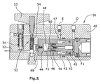
- the module 31 with the pressure amplifier 30 is in FIG. 2 shown.
- the module has a block 40 which contains a cylinder 41 with a booster piston 42 displaceable therein.
- the cylinder 41 has a large cylinder bore 43 and an adjoining small cylinder bore 44.
- the booster piston 42 has a first piston part 45 of large diameter and a second piston part 46 of small diameter.
- the piston area of the first piston part 45 is F1 and the piston area of the second piston part 46 is F2.
- the areas F1 and F2 are in the ratio 3: 1.
- the cylinder space bounded by the piston surface F1 is connected to the port D.
- the rear space 47 is connected to the terminal E.
- the small piston surface F2 defines a high pressure chamber 48, which is connected via a check valve 49 to the high pressure port 32.
- the booster piston 42 extends a longitudinal bore containing a check valve 50.
- the delivery pressure which acts on the piston surface F1
- the area ratio F1: F2 arises in the high-pressure chamber 48, an increased pressure.
- the delivery pressure is increased to the magnitude of the high pressure.
- a relief valve 52 which is to be operated with a handle 53, serves to remove the high pressure from the clamping cylinder unit 33, to relieve this.
- the relief valve 52 includes a spring-loaded ball which is urged against a valve seat and can be removed from the valve seat by a pin 54 of the handle. When open, this connects Relief valve 52 the port D to the high pressure port 32 so that it is relieved to the return.
- the pressure generating unit 10 is used only in conjunction with a power wrench 11 or with a clamping cylinder unit 33, but not with both together.
- a power wrench 11 is connected to the connections 16, 17 or the module 31.
- the stroke control of the piston 42 of the pressure booster 30 takes place through the lift switching valve 20 in the same control as in the power wrench operation.
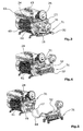
- FIGS. 3, 4 and 5 show different variants of the attachment of the module 31 to the pressure generating unit.
- the pressure generating unit has a housing 60 containing the pump 12 and the motor 13. This housing is closed at a front end by a distributor block 61, which the in FIG. 1 illustrated valve assembly carries.
- the distribution block also carries the manometer 25. From the outside is accessible to the manifold block, the pressure relief valve 24 for adjusting the delivery pressure PL and thus also the high pressure PH.
- the distribution block has the front side of the terminals 16 and 17, to which either a power wrench or a module 31 can be connected.
- the terminals 16 and 17 may be provided in duplicate, each unused ports are closed.
- the module 31 has the relief valve 52, the handle is accessible from the outside. In addition, the high-pressure port 32 can be seen.
- an attachment 62 which contains the electronic control unit 63 which controls the lift control device with the lift control valve 20.
- the control unit 63 receives inter alia the signals of the pressure sensors 22 and when operating the pressure supply unit with a clamping cylinder, it also provides an indication of the number of strokes carried out.
- the Figures 3 - 5 show different ways of attaching the module 31 to the manifold block 61 by direct connection or with hoses 64.
Landscapes
- Engineering & Computer Science (AREA)
- Mechanical Engineering (AREA)
- Physics & Mathematics (AREA)
- Fluid Mechanics (AREA)
- General Engineering & Computer Science (AREA)
- Fluid-Pressure Circuits (AREA)
- Supply Devices, Intensifiers, Converters, And Telemotors (AREA)
Abstract
Claims (6)
- Unité de distribution de pression pour visseuse mécanique (11), comportant- une unité de génération de pression (10) qui génère une pression de distribution (PL),- un dispositif de commande de course qui amène la pression de distribution alternativement à un premier raccord (16) et à un deuxième raccord (17) et relie l'autre des deux raccords à un retour (26),caractérisée en ce qui
il est prévu un amplificateur de pression (30) qui comporte une première partie de piston (45) de plus grand diamètre et une deuxième partie de piston (46) de plus petit diamètre, la première partie de piston étant commandée alternativement par les pressions des premier et deuxième raccords (16, 17) et la deuxième partie de piston (46) générant au niveau d'un raccord de haute pression (32) une haute pression (PH) qui est supérieure à la pression de distribution (PL), un dispositif à haute pression (33) pouvant être raccordé au raccord à haute pression (32). - Unité de distribution de pression hydraulique selon la revendication 1, caractérisée en ce que l'amplificateur de pression (30) est contenu dans un module séparé (31) qui est fixé de façon amovible à l'unité de génération pression (10).
- Unité de distribution de pression hydraulique selon la revendication 1 ou 2, caractérisée en ce que le dispositif de commande de course contient un clapet de commande de course (20) qui effectue la commutation de la pression de distribution (PL) entre un premier et un deuxième raccord (16, 17) en fonction de la variation de la pression dans le temps.
- Unité de distribution de pression hydraulique selon l'une des revendications 1 à 3, caractérisée en ce qu'un clapet de limitation de pression réglable (24) est prévu pour régler la pression de distribution (PL) et par conséquent également la haute pression (PH).
- Unité de distribution de pression hydraulique selon l'une des revendications 1 à 4, caractérisé en ce qu'il est prévu un clapet de décharge (52) qui est à ouverture manuelle et qui relie à l'état ouvert le deuxième raccord (17) au raccord à haute pression (32).
- Unité de distribution de pression hydraulique selon l'une des revendications 1 à 5, caractérisée en ce qu'il est prévu une unité de commande (63) qui ajoute, lorsque le dispositif de serrage de boulon (33) est en fonctionnement, en continu le nombre de courses de travail à la haute pression (PH) pour déterminer l'expiration de l'intervalle de maintenance.
Priority Applications (1)
| Application Number | Priority Date | Filing Date | Title |
|---|---|---|---|
| PL09719703T PL2249994T3 (pl) | 2008-03-12 | 2009-03-11 | Zespół hydraulicznego zasilacza ciśnieniowego dla wkrętarki mechanicznej |
Applications Claiming Priority (2)
| Application Number | Priority Date | Filing Date | Title |
|---|---|---|---|
| DE202008003500U DE202008003500U1 (de) | 2008-03-12 | 2008-03-12 | Hydraulische Druckliefereinheit für einen Kraftschrauber |
| PCT/EP2009/052850 WO2009112517A1 (fr) | 2008-03-12 | 2009-03-11 | Unité de production de pression hydraulique pour une visseuse mécanique |
Publications (2)
| Publication Number | Publication Date |
|---|---|
| EP2249994A1 EP2249994A1 (fr) | 2010-11-17 |
| EP2249994B1 true EP2249994B1 (fr) | 2012-06-27 |
Family
ID=40627717
Family Applications (1)
| Application Number | Title | Priority Date | Filing Date |
|---|---|---|---|
| EP09719703A Active EP2249994B1 (fr) | 2008-03-12 | 2009-03-11 | Unité de production de pression hydraulique pour une visseuse mécanique |
Country Status (7)
| Country | Link |
|---|---|
| US (1) | US8667789B2 (fr) |
| EP (1) | EP2249994B1 (fr) |
| DE (1) | DE202008003500U1 (fr) |
| DK (1) | DK2249994T3 (fr) |
| ES (1) | ES2388991T3 (fr) |
| PL (1) | PL2249994T3 (fr) |
| WO (1) | WO2009112517A1 (fr) |
Cited By (1)
| Publication number | Priority date | Publication date | Assignee | Title |
|---|---|---|---|---|
| EP2784331A1 (fr) * | 2013-03-25 | 2014-10-01 | miniBOOSTER HYDRAULICS A/S | Système hydraulique |
Families Citing this family (7)
| Publication number | Priority date | Publication date | Assignee | Title |
|---|---|---|---|---|
| DE102010015496B4 (de) * | 2010-04-16 | 2018-07-12 | Gedore Torque Solutions Gmbh | Gehäuse für ein Hydraulikaggregat |
| DE102010034187A1 (de) * | 2010-08-12 | 2012-02-16 | Lukas Hydraulik Gmbh | Steuereinrichtung für erstes und zweites Arbeitsgerät |
| JP5617945B2 (ja) * | 2013-02-26 | 2014-11-05 | コベルコクレーン株式会社 | 油圧回路および建設機械 |
| DE102016116880B4 (de) * | 2016-09-08 | 2018-03-22 | Tkr Spezialwerkzeuge Gmbh | Stationäre Hydraulikwerkzeugversorgungseinheit |
| GB2580113B (en) | 2018-12-21 | 2021-04-28 | Caterpillar Energy Solutions Gmbh | Device for tensioning a connecting element |
| EP4126459A1 (fr) | 2020-03-25 | 2023-02-08 | Milwaukee Electric Tool Corporation | Outil de serrage de boulon |
| GB202017991D0 (en) * | 2020-11-16 | 2020-12-30 | Acutension Ltd | Improved bolt tensioner |
Family Cites Families (13)
| Publication number | Priority date | Publication date | Assignee | Title |
|---|---|---|---|---|
| US3382669A (en) * | 1966-05-25 | 1968-05-14 | Burndy Corp | Hydraulic booster apparatus |
| GB1393618A (en) * | 1972-07-03 | 1975-05-07 | Nsw Corp | Wrenching |
| US4246810A (en) | 1979-05-10 | 1981-01-27 | Caterpillar Tractor Co. | Tool for pre-tensioning a fastener |
| US4523742A (en) * | 1982-01-25 | 1985-06-18 | Gripper, Inc. | Apparatus for tensioning a stud and method of doing same |
| DE3239596A1 (de) * | 1982-10-26 | 1984-05-03 | Alho, Harry, 78053 Nas | Druckmittelgesteuertes werkzeug |
| US5394693A (en) * | 1994-02-25 | 1995-03-07 | Daniels Manufacturing Corporation | Pneumatic/hydraulic remote power unit |
| JP3455479B2 (ja) * | 1999-09-22 | 2003-10-14 | 日精樹脂工業株式会社 | 射出成形機の油圧駆動装置 |
| DE19959569A1 (de) * | 1999-12-10 | 2001-06-13 | Mannesmann Rexroth Ag | Hydraulische Steueranordnung zum Steuern von zwei unterschiedlich hohen Drücken an einem hydraulischen Verbraucher, insbesondere von zwei unterschiedlich hohen Spanndrücken zum Halten eines Werkstücks in einer Werkzeugmaschine |
| DE10222159A1 (de) * | 2002-05-17 | 2003-11-27 | Paul-Heinz Wagner | Verfahren zur Steuerung einer hydraulischen Kolbenzylindereinheit |
| DE10249524B4 (de) * | 2002-10-23 | 2005-12-29 | Minibooster Hydraulics A/S | Fluid-Versorgungseinheit, insbesondere hydraulische Versorgungseinheit |
| US20090151517A1 (en) * | 2002-12-16 | 2009-06-18 | Martin Gosling | Bolted Assembly and Apparatus and Method for Tensioning the Bolted Assembly |
| DE102004007684C5 (de) * | 2004-02-16 | 2010-01-07 | Minibooster Hydraulics A/S | Tragbares hydraulisches Werkzeug |
| AT8986U1 (de) * | 2005-10-28 | 2007-03-15 | Hoerbiger Automatisierungstech | Hydraulische druckversorgungseinheit, sowie elektrohydraulische arbeitseinheit und spannsystem mit einer derartigen druckversorgungseinheit |
-
2008
- 2008-03-12 DE DE202008003500U patent/DE202008003500U1/de not_active Expired - Lifetime
-
2009
- 2009-03-11 DK DK09719703.2T patent/DK2249994T3/da active
- 2009-03-11 PL PL09719703T patent/PL2249994T3/pl unknown
- 2009-03-11 ES ES09719703T patent/ES2388991T3/es active Active
- 2009-03-11 US US12/922,309 patent/US8667789B2/en active Active
- 2009-03-11 WO PCT/EP2009/052850 patent/WO2009112517A1/fr not_active Ceased
- 2009-03-11 EP EP09719703A patent/EP2249994B1/fr active Active
Cited By (4)
| Publication number | Priority date | Publication date | Assignee | Title |
|---|---|---|---|---|
| EP2784331A1 (fr) * | 2013-03-25 | 2014-10-01 | miniBOOSTER HYDRAULICS A/S | Système hydraulique |
| CN104074809A (zh) * | 2013-03-25 | 2014-10-01 | 迷你液压增压器公司 | 液压系统 |
| CN104074809B (zh) * | 2013-03-25 | 2017-12-19 | 迷你液压增压器公司 | 液压系统 |
| US10337535B2 (en) | 2013-03-25 | 2019-07-02 | Minibooster Hydraulics A/S | Hydraulic system |
Also Published As
| Publication number | Publication date |
|---|---|
| WO2009112517A1 (fr) | 2009-09-17 |
| EP2249994A1 (fr) | 2010-11-17 |
| DK2249994T3 (da) | 2012-08-27 |
| ES2388991T3 (es) | 2012-10-22 |
| US8667789B2 (en) | 2014-03-11 |
| US20110005221A1 (en) | 2011-01-13 |
| PL2249994T3 (pl) | 2012-12-31 |
| DE202008003500U1 (de) | 2009-07-30 |
Similar Documents
| Publication | Publication Date | Title |
|---|---|---|
| EP2249994A1 (fr) | Unité de production de pression hydraulique pour une visseuse mécanique | |
| EP2016290A1 (fr) | Procede pour alimenter un cylindre moteur, commande de ce dernier, cylindre moteur et utilisation de celui-ci | |
| DE102010048068B4 (de) | Ventilanordnung | |
| DE102008030344A1 (de) | Kombiniertes Ansaugventil und elektrische Drucksteuerung für Farbsprühpumpen | |
| DE1909503U (de) | Druckmittelbetaetigter zylinder, insbesondere stellzylinder mit durchfluss- bzw. stellgeschwindigkeitssteuergliedern. | |
| EP1302663A1 (fr) | Groupe moto-pompe électro-hydraulique et clapet anti-retour | |
| EP4377571A1 (fr) | Pompe à piston haute pression et utilisation d'une pompe à piston haute pression | |
| DE112013003866T5 (de) | Autozyklus-Pumpe und Betriebsverfahren | |
| EP1818547A2 (fr) | Dispositif d'entretien d'air comprimé | |
| DE102018200680B4 (de) | Drucküberwachungsvorrichtung und damit ausgestattete Ventilanordnung | |
| WO1999066212A2 (fr) | Dispositif de reglage destine a des appareils hydrauliques | |
| DE3537337C2 (fr) | ||
| DE3332189C1 (de) | Landwirtschaftliches Gerät zum dosierten Ausbringen von Flüssigkeiten | |
| DE19521051C2 (de) | Hochdruckwasserstrahlbearbeitungseinrichtung | |
| EP1020643B1 (fr) | Bloc de sûreté de pression pour un nettoyeur à haute pression | |
| DE909295C (de) | Steuerung fuer Arbeitskolben von hydraulischen Pressen, Fahrzeughebern od. dgl. | |
| DE3105408C2 (de) | Bremsventil fuer hydraulische antriebe | |
| WO1990014258A1 (fr) | Systeme de freinage | |
| DE3501455A1 (de) | Leistungsregler fuer eine hydrostatische pumpe | |
| EP1963677A1 (fr) | Unite de compresseur | |
| EP2291586B1 (fr) | Dispositif destine a augmenter la pression dans des cylindres, avec equipement de commutation | |
| AT337531B (de) | Presse, insbesondere obst- oder weinpresse | |
| DE10110883C1 (de) | Blockierbares Kolben-Zylinderaggregat | |
| DE1627857C (de) | Ventilausbildung und Anordnung zur Gleichlaufsteuerung wahrend des Ruckhubes an pumpengetnebenen Mehrzylinderpressen | |
| DE102007042635A1 (de) | Fluidbetriebene Massageeinrichtung |
Legal Events
| Date | Code | Title | Description |
|---|---|---|---|
| PUAI | Public reference made under article 153(3) epc to a published international application that has entered the european phase |
Free format text: ORIGINAL CODE: 0009012 |
|
| 17P | Request for examination filed |
Effective date: 20100831 |
|
| AK | Designated contracting states |
Kind code of ref document: A1 Designated state(s): AT BE BG CH CY CZ DE DK EE ES FI FR GB GR HR HU IE IS IT LI LT LU LV MC MK MT NL NO PL PT RO SE SI SK TR |
|
| AX | Request for extension of the european patent |
Extension state: AL BA RS |
|
| DAX | Request for extension of the european patent (deleted) | ||
| REG | Reference to a national code |
Ref country code: DE Ref legal event code: R079 Ref document number: 502009003932 Country of ref document: DE Free format text: PREVIOUS MAIN CLASS: B25B0021000000 Ipc: F15B0011032000 |
|
| GRAP | Despatch of communication of intention to grant a patent |
Free format text: ORIGINAL CODE: EPIDOSNIGR1 |
|
| RIC1 | Information provided on ipc code assigned before grant |
Ipc: F15B 3/00 20060101ALI20111207BHEP Ipc: B25B 21/00 20060101ALI20111207BHEP Ipc: B25B 29/02 20060101ALI20111207BHEP Ipc: F15B 11/032 20060101AFI20111207BHEP |
|
| GRAS | Grant fee paid |
Free format text: ORIGINAL CODE: EPIDOSNIGR3 |
|
| GRAA | (expected) grant |
Free format text: ORIGINAL CODE: 0009210 |
|
| AK | Designated contracting states |
Kind code of ref document: B1 Designated state(s): AT BE BG CH CY CZ DE DK EE ES FI FR GB GR HR HU IE IS IT LI LT LU LV MC MK MT NL NO PL PT RO SE SI SK TR |
|
| REG | Reference to a national code |
Ref country code: GB Ref legal event code: FG4D Free format text: NOT ENGLISH |
|
| REG | Reference to a national code |
Ref country code: CH Ref legal event code: EP |
|
| REG | Reference to a national code |
Ref country code: AT Ref legal event code: REF Ref document number: 564401 Country of ref document: AT Kind code of ref document: T Effective date: 20120715 |
|
| REG | Reference to a national code |
Ref country code: IE Ref legal event code: FG4D Free format text: LANGUAGE OF EP DOCUMENT: GERMAN |
|
| REG | Reference to a national code |
Ref country code: DE Ref legal event code: R096 Ref document number: 502009003932 Country of ref document: DE Effective date: 20120823 |
|
| REG | Reference to a national code |
Ref country code: DK Ref legal event code: T3 |
|
| REG | Reference to a national code |
Ref country code: NL Ref legal event code: T3 |
|
| REG | Reference to a national code |
Ref country code: ES Ref legal event code: FG2A Ref document number: 2388991 Country of ref document: ES Kind code of ref document: T3 Effective date: 20121022 |
|
| PG25 | Lapsed in a contracting state [announced via postgrant information from national office to epo] |
Ref country code: FI Free format text: LAPSE BECAUSE OF FAILURE TO SUBMIT A TRANSLATION OF THE DESCRIPTION OR TO PAY THE FEE WITHIN THE PRESCRIBED TIME-LIMIT Effective date: 20120627 Ref country code: SE Free format text: LAPSE BECAUSE OF FAILURE TO SUBMIT A TRANSLATION OF THE DESCRIPTION OR TO PAY THE FEE WITHIN THE PRESCRIBED TIME-LIMIT Effective date: 20120627 Ref country code: LT Free format text: LAPSE BECAUSE OF FAILURE TO SUBMIT A TRANSLATION OF THE DESCRIPTION OR TO PAY THE FEE WITHIN THE PRESCRIBED TIME-LIMIT Effective date: 20120627 |
|
| REG | Reference to a national code |
Ref country code: NO Ref legal event code: T2 Effective date: 20120627 |
|
| REG | Reference to a national code |
Ref country code: LT Ref legal event code: MG4D Effective date: 20120627 |
|
| PG25 | Lapsed in a contracting state [announced via postgrant information from national office to epo] |
Ref country code: GR Free format text: LAPSE BECAUSE OF FAILURE TO SUBMIT A TRANSLATION OF THE DESCRIPTION OR TO PAY THE FEE WITHIN THE PRESCRIBED TIME-LIMIT Effective date: 20120928 Ref country code: HR Free format text: LAPSE BECAUSE OF FAILURE TO SUBMIT A TRANSLATION OF THE DESCRIPTION OR TO PAY THE FEE WITHIN THE PRESCRIBED TIME-LIMIT Effective date: 20120627 Ref country code: LV Free format text: LAPSE BECAUSE OF FAILURE TO SUBMIT A TRANSLATION OF THE DESCRIPTION OR TO PAY THE FEE WITHIN THE PRESCRIBED TIME-LIMIT Effective date: 20120627 Ref country code: SI Free format text: LAPSE BECAUSE OF FAILURE TO SUBMIT A TRANSLATION OF THE DESCRIPTION OR TO PAY THE FEE WITHIN THE PRESCRIBED TIME-LIMIT Effective date: 20120627 |
|
| REG | Reference to a national code |
Ref country code: PL Ref legal event code: T3 |
|
| PG25 | Lapsed in a contracting state [announced via postgrant information from national office to epo] |
Ref country code: IS Free format text: LAPSE BECAUSE OF FAILURE TO SUBMIT A TRANSLATION OF THE DESCRIPTION OR TO PAY THE FEE WITHIN THE PRESCRIBED TIME-LIMIT Effective date: 20121027 Ref country code: CZ Free format text: LAPSE BECAUSE OF FAILURE TO SUBMIT A TRANSLATION OF THE DESCRIPTION OR TO PAY THE FEE WITHIN THE PRESCRIBED TIME-LIMIT Effective date: 20120627 Ref country code: RO Free format text: LAPSE BECAUSE OF FAILURE TO SUBMIT A TRANSLATION OF THE DESCRIPTION OR TO PAY THE FEE WITHIN THE PRESCRIBED TIME-LIMIT Effective date: 20120627 Ref country code: EE Free format text: LAPSE BECAUSE OF FAILURE TO SUBMIT A TRANSLATION OF THE DESCRIPTION OR TO PAY THE FEE WITHIN THE PRESCRIBED TIME-LIMIT Effective date: 20120627 Ref country code: SK Free format text: LAPSE BECAUSE OF FAILURE TO SUBMIT A TRANSLATION OF THE DESCRIPTION OR TO PAY THE FEE WITHIN THE PRESCRIBED TIME-LIMIT Effective date: 20120627 Ref country code: CY Free format text: LAPSE BECAUSE OF FAILURE TO SUBMIT A TRANSLATION OF THE DESCRIPTION OR TO PAY THE FEE WITHIN THE PRESCRIBED TIME-LIMIT Effective date: 20120627 |
|
| PG25 | Lapsed in a contracting state [announced via postgrant information from national office to epo] |
Ref country code: PT Free format text: LAPSE BECAUSE OF FAILURE TO SUBMIT A TRANSLATION OF THE DESCRIPTION OR TO PAY THE FEE WITHIN THE PRESCRIBED TIME-LIMIT Effective date: 20121029 |
|
| PLBE | No opposition filed within time limit |
Free format text: ORIGINAL CODE: 0009261 |
|
| STAA | Information on the status of an ep patent application or granted ep patent |
Free format text: STATUS: NO OPPOSITION FILED WITHIN TIME LIMIT |
|
| 26N | No opposition filed |
Effective date: 20130328 |
|
| REG | Reference to a national code |
Ref country code: DE Ref legal event code: R097 Ref document number: 502009003932 Country of ref document: DE Effective date: 20130328 |
|
| PG25 | Lapsed in a contracting state [announced via postgrant information from national office to epo] |
Ref country code: BG Free format text: LAPSE BECAUSE OF FAILURE TO SUBMIT A TRANSLATION OF THE DESCRIPTION OR TO PAY THE FEE WITHIN THE PRESCRIBED TIME-LIMIT Effective date: 20120927 |
|
| BERE | Be: lapsed |
Owner name: WAGNER VERMOGENSVERWALTUNGS-GMBH & CO. K.G. Effective date: 20130331 |
|
| PG25 | Lapsed in a contracting state [announced via postgrant information from national office to epo] |
Ref country code: MC Free format text: LAPSE BECAUSE OF NON-PAYMENT OF DUE FEES Effective date: 20130331 |
|
| REG | Reference to a national code |
Ref country code: CH Ref legal event code: PL |
|
| REG | Reference to a national code |
Ref country code: IE Ref legal event code: MM4A |
|
| PG25 | Lapsed in a contracting state [announced via postgrant information from national office to epo] |
Ref country code: BE Free format text: LAPSE BECAUSE OF NON-PAYMENT OF DUE FEES Effective date: 20130331 Ref country code: LI Free format text: LAPSE BECAUSE OF NON-PAYMENT OF DUE FEES Effective date: 20130331 Ref country code: CH Free format text: LAPSE BECAUSE OF NON-PAYMENT OF DUE FEES Effective date: 20130331 Ref country code: IE Free format text: LAPSE BECAUSE OF NON-PAYMENT OF DUE FEES Effective date: 20130311 |
|
| PG25 | Lapsed in a contracting state [announced via postgrant information from national office to epo] |
Ref country code: MT Free format text: LAPSE BECAUSE OF FAILURE TO SUBMIT A TRANSLATION OF THE DESCRIPTION OR TO PAY THE FEE WITHIN THE PRESCRIBED TIME-LIMIT Effective date: 20120627 |
|
| PG25 | Lapsed in a contracting state [announced via postgrant information from national office to epo] |
Ref country code: HU Free format text: LAPSE BECAUSE OF FAILURE TO SUBMIT A TRANSLATION OF THE DESCRIPTION OR TO PAY THE FEE WITHIN THE PRESCRIBED TIME-LIMIT; INVALID AB INITIO Effective date: 20090311 Ref country code: MK Free format text: LAPSE BECAUSE OF FAILURE TO SUBMIT A TRANSLATION OF THE DESCRIPTION OR TO PAY THE FEE WITHIN THE PRESCRIBED TIME-LIMIT Effective date: 20120627 Ref country code: LU Free format text: LAPSE BECAUSE OF NON-PAYMENT OF DUE FEES Effective date: 20130311 |
|
| REG | Reference to a national code |
Ref country code: FR Ref legal event code: PLFP Year of fee payment: 8 |
|
| PGFP | Annual fee paid to national office [announced via postgrant information from national office to epo] |
Ref country code: NO Payment date: 20160321 Year of fee payment: 8 Ref country code: TR Payment date: 20160229 Year of fee payment: 8 |
|
| REG | Reference to a national code |
Ref country code: FR Ref legal event code: PLFP Year of fee payment: 9 |
|
| REG | Reference to a national code |
Ref country code: NO Ref legal event code: MMEP |
|
| PG25 | Lapsed in a contracting state [announced via postgrant information from national office to epo] |
Ref country code: NO Free format text: LAPSE BECAUSE OF NON-PAYMENT OF DUE FEES Effective date: 20170331 |
|
| REG | Reference to a national code |
Ref country code: FR Ref legal event code: PLFP Year of fee payment: 10 |
|
| PG25 | Lapsed in a contracting state [announced via postgrant information from national office to epo] |
Ref country code: TR Free format text: LAPSE BECAUSE OF NON-PAYMENT OF DUE FEES Effective date: 20170311 |
|
| PGFP | Annual fee paid to national office [announced via postgrant information from national office to epo] |
Ref country code: ES Payment date: 20250416 Year of fee payment: 17 |
|
| PGFP | Annual fee paid to national office [announced via postgrant information from national office to epo] |
Ref country code: IT Payment date: 20250331 Year of fee payment: 17 |
|
| PGFP | Annual fee paid to national office [announced via postgrant information from national office to epo] |
Ref country code: GB Payment date: 20260324 Year of fee payment: 18 |
|
| PGFP | Annual fee paid to national office [announced via postgrant information from national office to epo] |
Ref country code: DE Payment date: 20260316 Year of fee payment: 18 Ref country code: DK Payment date: 20260323 Year of fee payment: 18 |
|
| PGFP | Annual fee paid to national office [announced via postgrant information from national office to epo] |
Ref country code: AT Payment date: 20260319 Year of fee payment: 18 |
|
| PGFP | Annual fee paid to national office [announced via postgrant information from national office to epo] |
Ref country code: NL Payment date: 20260323 Year of fee payment: 18 |
|
| PGFP | Annual fee paid to national office [announced via postgrant information from national office to epo] |
Ref country code: FR Payment date: 20260325 Year of fee payment: 18 |
|
| PGFP | Annual fee paid to national office [announced via postgrant information from national office to epo] |
Ref country code: PL Payment date: 20260303 Year of fee payment: 18 |