EP2250397B1 - Betätigungsanordnung eines zentralsynchronisierten doppelkupplungsgetriebes - Google Patents
Betätigungsanordnung eines zentralsynchronisierten doppelkupplungsgetriebes Download PDFInfo
- Publication number
- EP2250397B1 EP2250397B1 EP09720790.6A EP09720790A EP2250397B1 EP 2250397 B1 EP2250397 B1 EP 2250397B1 EP 09720790 A EP09720790 A EP 09720790A EP 2250397 B1 EP2250397 B1 EP 2250397B1
- Authority
- EP
- European Patent Office
- Prior art keywords
- transmission
- actuating assembly
- assembly according
- synchronization means
- actuator
- Prior art date
- Legal status (The legal status is an assumption and is not a legal conclusion. Google has not performed a legal analysis and makes no representation as to the accuracy of the status listed.)
- Not-in-force
Links
- 230000005540 biological transmission Effects 0.000 title claims description 98
- 230000001360 synchronised effect Effects 0.000 title claims description 9
- 230000008878 coupling Effects 0.000 description 4
- 238000010168 coupling process Methods 0.000 description 4
- 238000005859 coupling reaction Methods 0.000 description 4
- 238000010586 diagram Methods 0.000 description 2
- 230000009977 dual effect Effects 0.000 description 2
- 238000003199 nucleic acid amplification method Methods 0.000 description 2
- 230000001154 acute effect Effects 0.000 description 1
- 210000000078 claw Anatomy 0.000 description 1
- 238000002485 combustion reaction Methods 0.000 description 1
- 238000010276 construction Methods 0.000 description 1
- 230000001419 dependent effect Effects 0.000 description 1
- 238000009434 installation Methods 0.000 description 1
- 238000004519 manufacturing process Methods 0.000 description 1
- 230000009347 mechanical transmission Effects 0.000 description 1
- 230000002093 peripheral effect Effects 0.000 description 1
Images


Classifications
-
- F—MECHANICAL ENGINEERING; LIGHTING; HEATING; WEAPONS; BLASTING
- F16—ENGINEERING ELEMENTS AND UNITS; GENERAL MEASURES FOR PRODUCING AND MAINTAINING EFFECTIVE FUNCTIONING OF MACHINES OR INSTALLATIONS; THERMAL INSULATION IN GENERAL
- F16H—GEARING
- F16H61/00—Control functions within control units of change-speed- or reversing-gearings for conveying rotary motion ; Control of exclusively fluid gearing, friction gearing, gearings with endless flexible members or other particular types of gearing
- F16H61/68—Control functions within control units of change-speed- or reversing-gearings for conveying rotary motion ; Control of exclusively fluid gearing, friction gearing, gearings with endless flexible members or other particular types of gearing specially adapted for stepped gearings
- F16H61/684—Control functions within control units of change-speed- or reversing-gearings for conveying rotary motion ; Control of exclusively fluid gearing, friction gearing, gearings with endless flexible members or other particular types of gearing specially adapted for stepped gearings without interruption of drive
- F16H61/688—Control functions within control units of change-speed- or reversing-gearings for conveying rotary motion ; Control of exclusively fluid gearing, friction gearing, gearings with endless flexible members or other particular types of gearing specially adapted for stepped gearings without interruption of drive with two inputs, e.g. selection of one of two torque-flow paths by clutches
-
- F—MECHANICAL ENGINEERING; LIGHTING; HEATING; WEAPONS; BLASTING
- F16—ENGINEERING ELEMENTS AND UNITS; GENERAL MEASURES FOR PRODUCING AND MAINTAINING EFFECTIVE FUNCTIONING OF MACHINES OR INSTALLATIONS; THERMAL INSULATION IN GENERAL
- F16D—COUPLINGS FOR TRANSMITTING ROTATION; CLUTCHES; BRAKES
- F16D49/00—Brakes with a braking member co-operating with the periphery of a drum, wheel-rim, or the like
- F16D49/08—Brakes with a braking member co-operating with the periphery of a drum, wheel-rim, or the like shaped as an encircling band extending over approximately 360 degrees
-
- F—MECHANICAL ENGINEERING; LIGHTING; HEATING; WEAPONS; BLASTING
- F16—ENGINEERING ELEMENTS AND UNITS; GENERAL MEASURES FOR PRODUCING AND MAINTAINING EFFECTIVE FUNCTIONING OF MACHINES OR INSTALLATIONS; THERMAL INSULATION IN GENERAL
- F16D—COUPLINGS FOR TRANSMITTING ROTATION; CLUTCHES; BRAKES
- F16D63/00—Brakes not otherwise provided for; Brakes combining more than one of the types of groups F16D49/00 - F16D61/00
-
- F—MECHANICAL ENGINEERING; LIGHTING; HEATING; WEAPONS; BLASTING
- F16—ENGINEERING ELEMENTS AND UNITS; GENERAL MEASURES FOR PRODUCING AND MAINTAINING EFFECTIVE FUNCTIONING OF MACHINES OR INSTALLATIONS; THERMAL INSULATION IN GENERAL
- F16D—COUPLINGS FOR TRANSMITTING ROTATION; CLUTCHES; BRAKES
- F16D65/00—Parts or details
- F16D65/14—Actuating mechanisms for brakes; Means for initiating operation at a predetermined position
-
- F—MECHANICAL ENGINEERING; LIGHTING; HEATING; WEAPONS; BLASTING
- F16—ENGINEERING ELEMENTS AND UNITS; GENERAL MEASURES FOR PRODUCING AND MAINTAINING EFFECTIVE FUNCTIONING OF MACHINES OR INSTALLATIONS; THERMAL INSULATION IN GENERAL
- F16H—GEARING
- F16H3/00—Toothed gearings for conveying rotary motion with variable gear ratio or for reversing rotary motion
- F16H3/02—Toothed gearings for conveying rotary motion with variable gear ratio or for reversing rotary motion without gears having orbital motion
- F16H3/08—Toothed gearings for conveying rotary motion with variable gear ratio or for reversing rotary motion without gears having orbital motion exclusively or essentially with continuously meshing gears, that can be disengaged from their shafts
- F16H3/12—Toothed gearings for conveying rotary motion with variable gear ratio or for reversing rotary motion without gears having orbital motion exclusively or essentially with continuously meshing gears, that can be disengaged from their shafts with means for synchronisation not incorporated in the clutches
-
- F—MECHANICAL ENGINEERING; LIGHTING; HEATING; WEAPONS; BLASTING
- F16—ENGINEERING ELEMENTS AND UNITS; GENERAL MEASURES FOR PRODUCING AND MAINTAINING EFFECTIVE FUNCTIONING OF MACHINES OR INSTALLATIONS; THERMAL INSULATION IN GENERAL
- F16D—COUPLINGS FOR TRANSMITTING ROTATION; CLUTCHES; BRAKES
- F16D2121/00—Type of actuator operation force
- F16D2121/18—Electric or magnetic
- F16D2121/24—Electric or magnetic using motors
-
- F—MECHANICAL ENGINEERING; LIGHTING; HEATING; WEAPONS; BLASTING
- F16—ENGINEERING ELEMENTS AND UNITS; GENERAL MEASURES FOR PRODUCING AND MAINTAINING EFFECTIVE FUNCTIONING OF MACHINES OR INSTALLATIONS; THERMAL INSULATION IN GENERAL
- F16D—COUPLINGS FOR TRANSMITTING ROTATION; CLUTCHES; BRAKES
- F16D2125/00—Components of actuators
- F16D2125/18—Mechanical mechanisms
- F16D2125/44—Mechanical mechanisms transmitting rotation
- F16D2125/46—Rotating members in mutual engagement
- F16D2125/52—Rotating members in mutual engagement with non-parallel stationary axes, e.g. worm or bevel gears
-
- F—MECHANICAL ENGINEERING; LIGHTING; HEATING; WEAPONS; BLASTING
- F16—ENGINEERING ELEMENTS AND UNITS; GENERAL MEASURES FOR PRODUCING AND MAINTAINING EFFECTIVE FUNCTIONING OF MACHINES OR INSTALLATIONS; THERMAL INSULATION IN GENERAL
- F16D—COUPLINGS FOR TRANSMITTING ROTATION; CLUTCHES; BRAKES
- F16D2125/00—Components of actuators
- F16D2125/18—Mechanical mechanisms
- F16D2125/58—Mechanical mechanisms transmitting linear movement
- F16D2125/64—Levers
-
- F—MECHANICAL ENGINEERING; LIGHTING; HEATING; WEAPONS; BLASTING
- F16—ENGINEERING ELEMENTS AND UNITS; GENERAL MEASURES FOR PRODUCING AND MAINTAINING EFFECTIVE FUNCTIONING OF MACHINES OR INSTALLATIONS; THERMAL INSULATION IN GENERAL
- F16H—GEARING
- F16H3/00—Toothed gearings for conveying rotary motion with variable gear ratio or for reversing rotary motion
- F16H3/02—Toothed gearings for conveying rotary motion with variable gear ratio or for reversing rotary motion without gears having orbital motion
- F16H3/08—Toothed gearings for conveying rotary motion with variable gear ratio or for reversing rotary motion without gears having orbital motion exclusively or essentially with continuously meshing gears, that can be disengaged from their shafts
- F16H3/12—Toothed gearings for conveying rotary motion with variable gear ratio or for reversing rotary motion without gears having orbital motion exclusively or essentially with continuously meshing gears, that can be disengaged from their shafts with means for synchronisation not incorporated in the clutches
- F16H2003/123—Toothed gearings for conveying rotary motion with variable gear ratio or for reversing rotary motion without gears having orbital motion exclusively or essentially with continuously meshing gears, that can be disengaged from their shafts with means for synchronisation not incorporated in the clutches using a brake
-
- F—MECHANICAL ENGINEERING; LIGHTING; HEATING; WEAPONS; BLASTING
- F16—ENGINEERING ELEMENTS AND UNITS; GENERAL MEASURES FOR PRODUCING AND MAINTAINING EFFECTIVE FUNCTIONING OF MACHINES OR INSTALLATIONS; THERMAL INSULATION IN GENERAL
- F16H—GEARING
- F16H61/00—Control functions within control units of change-speed- or reversing-gearings for conveying rotary motion ; Control of exclusively fluid gearing, friction gearing, gearings with endless flexible members or other particular types of gearing
- F16H61/04—Smoothing ratio shift
- F16H61/0403—Synchronisation before shifting
- F16H2061/0411—Synchronisation before shifting by control of shaft brakes
-
- F—MECHANICAL ENGINEERING; LIGHTING; HEATING; WEAPONS; BLASTING
- F16—ENGINEERING ELEMENTS AND UNITS; GENERAL MEASURES FOR PRODUCING AND MAINTAINING EFFECTIVE FUNCTIONING OF MACHINES OR INSTALLATIONS; THERMAL INSULATION IN GENERAL
- F16H—GEARING
- F16H63/00—Control outputs from the control unit to change-speed- or reversing-gearings for conveying rotary motion or to other devices than the final output mechanism
- F16H63/02—Final output mechanisms therefor; Actuating means for the final output mechanisms
- F16H63/30—Constructional features of the final output mechanisms
- F16H63/3003—Band brake actuating mechanisms
- F16H2063/3006—Band brake actuating mechanisms moved by a non-mechanical force
-
- F—MECHANICAL ENGINEERING; LIGHTING; HEATING; WEAPONS; BLASTING
- F16—ENGINEERING ELEMENTS AND UNITS; GENERAL MEASURES FOR PRODUCING AND MAINTAINING EFFECTIVE FUNCTIONING OF MACHINES OR INSTALLATIONS; THERMAL INSULATION IN GENERAL
- F16H—GEARING
- F16H2306/00—Shifting
- F16H2306/40—Shifting activities
- F16H2306/48—Synchronising of new gear
-
- Y—GENERAL TAGGING OF NEW TECHNOLOGICAL DEVELOPMENTS; GENERAL TAGGING OF CROSS-SECTIONAL TECHNOLOGIES SPANNING OVER SEVERAL SECTIONS OF THE IPC; TECHNICAL SUBJECTS COVERED BY FORMER USPC CROSS-REFERENCE ART COLLECTIONS [XRACs] AND DIGESTS
- Y10—TECHNICAL SUBJECTS COVERED BY FORMER USPC
- Y10T—TECHNICAL SUBJECTS COVERED BY FORMER US CLASSIFICATION
- Y10T74/00—Machine element or mechanism
- Y10T74/19—Gearing
- Y10T74/19219—Interchangeably locked
- Y10T74/19233—Plurality of counter shafts
-
- Y—GENERAL TAGGING OF NEW TECHNOLOGICAL DEVELOPMENTS; GENERAL TAGGING OF CROSS-SECTIONAL TECHNOLOGIES SPANNING OVER SEVERAL SECTIONS OF THE IPC; TECHNICAL SUBJECTS COVERED BY FORMER USPC CROSS-REFERENCE ART COLLECTIONS [XRACs] AND DIGESTS
- Y10—TECHNICAL SUBJECTS COVERED BY FORMER USPC
- Y10T—TECHNICAL SUBJECTS COVERED BY FORMER US CLASSIFICATION
- Y10T74/00—Machine element or mechanism
- Y10T74/19—Gearing
- Y10T74/19219—Interchangeably locked
- Y10T74/19284—Meshing assisters
Definitions
- the present invention relates to an actuating arrangement for actuating synchronization means of a centrally synchronized dual-clutch transmission according to the closer defined in the preamble of claim 1.
- the document EP 1 400 731 shows the closest prior art with all features of the preamble of claim 1.
- a coupling device with a clutch and a transmission brake for an internal combustion engine with a transmission known.
- the provided for actuating the clutch coupling device also has a transmission element by means of which the movement of the clutch is mechanically transferable to the transmission brake, so that an individual driving the transmission brake is possible.
- a launch clutch system for a vehicle which comprises a starting clutch and a transmission brake.
- the starting clutch and the transmission brake are actuated via an actuator. From the aforementioned publications it is thus known that the actuator provided for actuating the clutch is also provided for actuating a transmission brake.
- each partial transmission and thus each transmission input shaft are assigned a synchronization means.
- at least two actuators are required, each actuate a synchronization means.
- synchronization means different versions, such as classic synchronizers or transmission brakes for differential speed compensation are known.
- a synchronization means in number of idler gears to be switched is arranged. In this embodiment, further actuators are required to operate the synchronization means at each switching point.
- the present invention is based on the object to propose an actuating arrangement of a centrally synchronized dual-clutch transmission of the type described above, in which a particularly cost and space-saving actuator is provided.
- an actuating arrangement for actuating synchronization means of a centrally synchronized dual-clutch transmission with at least one first partial transmission and a second partial transmission wherein each partial transmission is associated with at least one synchronization means.
- at least the synchronization means of the two partial transmissions can be actuated via a common actuator.
- only one actuator is required for both synchronization means, in addition to the cost savings also results in a space advantage.
- a savings can also be made in the electrical control device for driving the actuator with regard to the required installation space and the production costs. It is also possible that further provided synchronization means of the transmission are actuated with the actuator.
- the synchronization means of the first partial transmission or the synchronization means of the second partial transmission can be controlled depending on the respective direction of movement of the actuator from its zero position out.
- other control possibilities of the synchronization means of the two partial transmissions are also conceivable.
- the so-called combination actuator of the actuating arrangement according to the invention can act with a transmission means on the two synchronization means. It is also possible that two transmission means are provided on the actuator, each acting on a synchronization means.
- mechanical, hydraulic, pneumatic or the like means can be used as a means of transmission.
- a variant of the actuator assembly according to the invention with only one transmission means which can be designed as a component, provide that the transmission means includes at least one eccentric.
- the transmission means includes at least one eccentric.
- two eccentrics are arranged on a shaft and thus combined to form a double eccentric shaft.
- the ends of the eccentric are each connected to a movable end of the example formed as a band brake synchronization means.
- the eccentric shaft can actuate both synchronization means by the actuator.
- the structural design of the double eccentric shaft can be designed such that the two eccentrics are arranged, for example, axially with each other.
- the eccentrics may be formed as cranked portions of the double eccentric shaft, which are arranged in the circumferential direction of the double eccentric shaft at a predetermined angle to each other.
- the eccentric can be arranged distributed at an angle of about 180 ° around the circumference.
- the eccentric shaft can be actuated, for example, via a toothed segment disc.
- Another embodiment of the actuating arrangement according to the invention with e.g. two means of transmission may provide that as transmission means each as e.g. Gear brake trained synchronization means is associated with a lever element or the like, wherein the two lever elements via a common actuating element, e.g. a driven by the actuator toothed segment disc or the like are actuated.
- the coupling of the transmission means to the common actuator can be done for example via plunger.
- the actuator drives the lever elements designed as transmission means, which then each act separately on the respective synchronization means.
- a toothed output shaft of e.g. formed as an electric motor actuator are in engagement with a toothing of the toothed segment disc, wherein the axis of rotation of the toothed segment disc is equipped with receiving portions or the like, which are in operative connection via an articulation lever or plunger with the associated lever elements.
- the axis of rotation of the respective lever element may be fixed to the housing at the end facing away from the toothed segment disc, on which also the housing-fixed end of the band brake designed as a gear brake is held, wherein the movable end of the band brake e.g. may be attached to the respective lever element between the two ends.
- other designs are conceivable.
- the synchronization means is assigned to a gear gear with the highest ratio of the respective sub-transmission.
- the actuator can be arranged, for example, substantially parallel to the axis or perpendicular to the countershafts of the dual clutch transmission. Again, other arrangement options are conceivable.
- each synchronization means e.g. is arranged concentrically to the respective circuit on one of the countershafts.
- the synchronization means can be accommodated in the same axial space, so that a radial nested construction is possible.
- the actuator provided for actuating the two synchronization means can be, for example, an electric motor, in the form of a rotary or linear motor or the like. It is also possible that an electromagnet or a cylinder-piston unit is used as the actuator.
- each partial transmission can be assigned at least one transmission brake and / or one clutch.
- a transmission brakes band brakes multi-disc brake and / or cone brake can be provided, for example.
- the required brake drum, brake disc or brake cone can be made in one piece with the associated fixed or idler gear.
- the transmission brake There are also other structural embodiments of the transmission brake conceivable.
- a coupling for example, a cone clutch, a multi-plate clutch or the like may be provided.
- the switching elements or switching devices for gear selection can preferably be actuated out of the shaft with a so-called internal operation.
- the switching elements themselves may be, for example, claws or the like. There are also other switching elements usable.
- FIGS. 1 to 6 show various embodiments of an actuator assembly according to the invention for actuating synchronization means in a centrally synchronized dual-clutch transmission with a first partial transmission 6 and a second partial transmission 7, wherein each partial transmission 6, 7 is associated with a synchronization means.
- each partial transmission 6, 7 is associated with a synchronization means.
- the dual-clutch transmission is in the inventive Actuating arrangement provided that the two synchronization means of the partial transmission 6, 7 can be actuated by means of a common actuator 1.
- the actuator 1 is provided as Kombiaktuator, which can selectively operate the Getriebesynchronisationsstoff the parallel-connected partial transmission 6, 7.
- the actuator assembly includes as an actuator 1, an electric motor 2, which drives an output shaft 3.
- the actuating arrangement is configured such that the band brake 4 of the first partial transmission 6 or the band brake 5 of the second partial transmission 7 is controlled as a function of the respective direction of movement of the actuator 1 from its zero position.
- FIGS. 1 and 2 a first possible embodiment of the actuator assembly according to the invention is shown on the centrally synchronized dual-clutch transmission.
- two mechanical transmission means between the electric motor 2 and the band brakes 4, 5 are provided for transmitting the rotational movement of the electric motor 2 and the output shaft 3 to the respective band brakes 4, 5.
- Each transmission means comprises a lever element 8, 8 ', which in each case via a plunger 9, 9' with a driven by the output shaft 3 of the electric motor 2 toothed disk segment 10 is in operative connection.
- the teeth having an output shaft 3 of the electric motor 2 is in engagement with a toothing 11 of the toothed disk 10, wherein the axis of rotation 12 of the toothed disk 10 is equipped with receiving portions 13,14, respectively via the plunger 9, 9 'with the facing end of the respective Lever element 8, 8 'are in operative connection.
- the the plunger 9, 9 'facing away from the end of the respective lever element 8, 8' is as a rotation axis 15, 15 'stored fixed to the housing.
- the axis of rotation 15, 15 'forming end of the respective lever member 8, 8' simultaneously serves to receive the housing fixed end of the respective band brake 4, 5.
- the movable or actuatable end for actuating the band brake 4, 5 is in each case on the respective lever element 8, eighth 'added between the two ends.
- the associated band brake 4, 5 ' can be activated or tensioned or released or relaxed by the pivoting of the respective lever element 8, 8'.
- the electric motor 2 is arranged approximately perpendicular to the two countershafts w_v1, w_v2 and the transmission input shafts w_k1, w_k2 of the two partial transmissions 6, 7 of the exemplified double clutch transmission.
- the toothing 11 of the toothed segment disc 10 is provided radially outside on the peripheral region of the toothed segment disc 10.
- the electric motor 2 is arranged approximately parallel or a predetermined, in particular acute angle to the two countershafts w_v1, w_v2 and the transmission input shafts w_k1, w_k2 of the two partial transmissions 6, 7 of the dual clutch transmission.
- the toothing 11 of the toothed segment disc 10 is provided on the surface.
- the receiving portions 13,14 can be arranged at an angle of 180 ° to the circumference of the axis of rotation of the toothed segment disc 10 to each other in the first embodiment. There are also other angles conceivable.
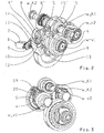
- FIGS. 3 to 5 views of a second possible embodiment are shown, wherein like components are denoted by the same reference numerals as in the first embodiment.
- only one transmission means is provided for transmitting the direction of movement of the electric motor 2 to the band brakes 4, 5.
- a transmission means a double eccentric shaft 20 is provided, the eccentric 16,17 are each connected to the movable end of the respective band brake 4, 5.
- the housing-fixed ends of the band brakes 4, 5 are fixed to a bearing pin 18, which is held with its ends in receiving sockets of a support unit 19.
- the double eccentric shaft 20 is rotatably supported in the carrier unit 19.
- the two eccentrics 16,17 of the double eccentric shaft 20 are arranged one behind the other in the axial direction and offset in the circumferential direction at an angle of approximately 180 ° to each other. There are other angles possible.
- the band brakes 4, 5 facing away from the end of the double eccentric shaft 20 is in a manner not shown with the output shaft 3 of the electric motor 2 in operative connection.
- FIG. 6 is a schematic diagram of a possible dual-clutch transmission with the indication of the location of the synchronization means on the two partial transmissions 6, 7 shown. From this representation, it follows that the synchronization means are respectively assigned to the highest gear of the respective subtransmission 6, 7.
- the synchronization means are actuated in a prescribed manner by the schematically indicated actuator 1.
- the outgoing of the actuator 1 arrows point to the respective location of the synchronization means and are to represent the transfer means schematically.
- the transmission input shaft w_k2 associated with the second subgear 7, which is associated with the clutch K2 and the output shaft w_ab.
- band brakes 4, 5 are actuated via the lever elements 8, 8 'or the double eccentric shaft 20, a self-amplification and thus a lower braking force is required in an operation on the leading side of the brake band, wherein the band brakes 4, 5 coefficient of friction are more sensitive. If the actuation takes place on the running side of the brake band, no self-amplification occurs, so that higher braking forces are required, the band brakes 4, 5 then friction coefficient are less sensitive. This may possibly be done a better dosage of the braking force. Regardless of the particular embodiment, a suitable friction lining is applied to the brake band of each band brake 4, 5.
- a return element to ensure a clearance on the brake band.
- a return element For example, a return spring or the like can be used.
Landscapes
- Engineering & Computer Science (AREA)
- General Engineering & Computer Science (AREA)
- Mechanical Engineering (AREA)
- Gear-Shifting Mechanisms (AREA)
- Braking Arrangements (AREA)
- Control Of Transmission Device (AREA)
Description
- Die vorliegende Erfindung betrifft eine Betätigungsanordnung zum Betätigen von Synchronisationsmitteln eines zentralsynchronisierten Doppelkupplungsgetriebes gemäß der im Oberbegriff des Patentanspruches 1 näher definierten Art.
- Das Dokument
EP 1 400 731 zeigt den nächstliegenden Stand der Technik mit allen Merkmalen des Oberbegriffs des Anspruchs 1. - Beispielsweise aus der Druckschrift
DE 10 2006 015 898 A1 ist eine Kupplungseinrichtung mit einer Kupplung und einer Getriebebremse für eine Verbrennungskraftmaschine mit einem Getriebe bekannt. Die zur Betätigung der Kupplung vorgesehene Kupplungseinrichtung weist zudem ein Übertragungselement auf, mittels dessen die Bewegung der Kupplung mechanisch auf die Getriebebremse übertragbar ist, so dass ein individuelles Ansteuern der Getriebebremse möglich ist. Ferner ist aus der DruckschriftDE 10 2004 002 045 A1 ein Anfahrkupplungssystem für ein Fahrzeug bekannt, welches eine Anfahrkupplung und eine Getriebebremse umfasst. Die Anfahrkupplung und die Getriebebremse werden über einen Aktuator betätigt. Aus den vorgenannten Druckschriften ist somit bekannt, dass der zur Betätigung der Kupplung vorgesehene Aktuator auch zur Betätigung einer Getriebebremse vorgesehen ist. - Bei den vorgeschriebenen zentralsynchronisierten Getrieben mit nur einer Getriebeeingangswelle ist demzufolge auch nur ein Synchronisationsmittel an der Getriebeeingangswelle vorgesehen. Im Gegensatz dazu sind bei zentralsynchronisierten Doppelkupplungsgetrieben jedem Teilgetriebe und damit jeder Getriebeeingangswelle ein Synchronisationsmittel zugeordnet. Somit sind zumindest zwei Aktuatoren erforderlich, die jeweils ein Synchronisationsmittel betätigen. Als Synchronisationsmittel sind verschiedene Ausführungen, wie z.B. klassische Synchronisierungen beziehungsweise Getriebebremsen zum Differenzdrehzahlausgleich bekannt. Es ist auch möglich, dass an jeder Schaltstelle ein Synchronisationsmittel in Zahl der zu schaltenden Losräder angeordnet ist. Bei dieser Ausführungsvariante sind weitere Aktuatoren erforderlich, um die Synchronisationsmittel an jeder Schaltstelle zu betätigen.
- Der vorliegenden Erfindung liegt die Aufgabe zu Grunde, eine Betätigungsanordnung eines zentralsynchronisierten Doppelkupplungsgetriebes der eingangs beschriebenen Gattung vorzuschlagen, bei dem eine besonders kosten- und bauraumgünstige Aktuatorik vorgesehen ist.
- Diese Aufgabe wird erfindungsgemäß durch die Merkmale des Patentanspruches 1 gelöst. Weitere vorteilhafte Ausgestaltungen ergeben sich aus den Unteransprüchen und den Zeichnungen.
- Demnach wird eine Betätigungsanordnung zum Betätigen von Synchronisationsmitteln eines zentralsynchronisierten Doppelkupplungsgetriebes mit zumindest einem ersten Teilgetriebe und einen zweiten Teilgetriebe vorgeschlagen, wobei jedem Teilgetriebe zumindest ein Synchronisationsmittel zugeordnet ist. Erfindungsgemäß ist vorgesehen, dass zumindest die Synchronisationsmittel der beiden Teilgetriebe über einen gemeinsamen Aktuator betätigbar sind. Dadurch, dass nur ein Aktuator für beide Synchronisationsmittel erforderlich ist, ergibt sich neben der Kostenersparnis auch ein Bauraumvorteil. Zudem kann auch bei dem elektrischen Steuergerät zum Ansteuern des Aktuators hinsichtlich des erforderlichen Bauraumes und der Herstellungskosten eine Einsparung erfolgen. Es ist auch möglich, dass mit dem Aktuator weitere vorgesehene Synchronisationsmittel des Getriebes betätigt werden.
- Im Rahmen einer vorteilhaften Weiterbildung der Erfindung kann vorgesehen sein, dass in Abhängigkeit der jeweiligen Bewegungsrichtung des Aktuators aus seiner Nulllage heraus das Synchronisationsmittel des ersten Teilgetriebes oder das Synchronisationsmittel des zweiten Teilgetriebes ansteuerbar ist. Dadurch ergibt sich der Vorteil einer höheren Funktionssicherheit bei dem Doppelkupplungsgetriebe, da in keinem Fall beide Synchronisationsmittel gleichzeitig angesteuert werden können. Auf diese Weise können die Synchronisationsmittel nie gegeneinander wirken. Es sind jedoch auch andere Ansteuerungsmöglichkeiten der Synchronisationsmittel der beiden Teilgetriebe denkbar.
- Gemäß einer möglichen Ausgestaltung der Erfindung kann vorgesehen sein, dass zur Übertragung der Bewegungsrichtung des Aktuators auf die Synchronisationsmittel zumindest ein Übertragungsmittel oder dergleichen zwischen dem Aktuator und den jeweiligen Synchronisationsmittel vorgesehen ist. Beispielsweise kann der so genannte Kombiaktuator der erfindungsgemäßen Betätigungsanordnung mit einem Übertragungsmittel auf die beiden Synchronisationsmittel wirken. Es ist auch möglich, dass zwei Übertragungsmittel an dem Aktuator vorgesehen sind, die jeweils auf ein Synchronisationsmittel wirken. Als Übertragungsmittel können mechanische, hydraulische, pneumatische oder dergleichen Mittel eingesetzt werden.
- Beispielsweise kann eine Ausführungsvariante der erfindungsgemäßen Betätigungsanordnung mit nur einem Übertragungsmittel, welches als ein Bauteil ausgeführt sein kann, vorsehen, dass das Übertragungsmittel zumindest einen Exzenter enthält. In einer bevorzugten Ausführungsvariante werden zwei Exzenter auf einer Welle angeordnet und somit zu einer Doppelexzenterwelle zusammengefasst. Die Enden der Exzenter sind jeweils mit einem bewegbaren Ende des z.B. als Bandbremse ausgebildeten Synchronisationsmittel verbunden. Auf diese Weise kann die Exzenterwelle beide Synchronisationsmittel durch den Aktuator betätigen. Die konstruktive Ausführung der Doppelexzenterwelle kann derart gestaltet sein, dass die beiden Exzenter beispielsweise axial miteinander angeordnet sind. Dabei können die Exzenter als gekröpfte Bereiche der Doppelexzenterwelle ausgebildet sein, welche in Umfangsrichtung der Doppelexzenterwelle in einem vorbestimmten Winkel zueinander angeordnet sind. Beispielsweise können die Exzenter in einem Winkel von etwa 180° über den Umfang verteilt angeordnet sein. Die Exzenterwelle ist z.B. über eine Zahnsegmentscheibe betätigbar.
- Eine andere Ausführungsvariante der erfindungsgemäßen Betätigungsanordnung mit z.B. zwei Übertragungsmittel kann vorsehen, dass als Übertragungsmittel jedem als z.B. Getriebebremse ausgebildeten Synchronisationsmittel ein Hebelelement oder dergleichen zugeordnet ist, wobei die beiden Hebelelemente über ein gemeinsames Betätigungselement, z.B. eine von dem Aktuator angetriebene Zahnsegmentscheibe oder dergleichen betätigbar sind. Die Ankoppelung der Übertragungsmittel an das gemeinsame Betätigungselement kann beispielsweise über Stößel erfolgen. Bei dieser Ausführungsvariante treibt der Aktuator die als Übertragungsmittel ausgebildeten Hebelelemente an, die dann jeweils separat auf das jeweilige Synchronisationsmittel wirken.
- Bei der vorgenannten Ausführungsvariante kann beispielsweise eine verzahnte Ausgangswelle eines z.B. als Elektromotor ausgebildeten Aktuators mit einer Verzahnung der Zahnsegmentscheibe in Eingriff stehen, wobei die Drehachse der Zahnsegmentscheibe mit Aufnahmeabschnitten oder dergleichen ausgerüstet ist, welche jeweils über einen Anlenkhebel bzw. Stößel mit den zugeordneten Hebelelementen in Wirkverbindung stehen. Somit kann je nach Drehrichtung des Aktuators die eine oder andere Getriebebremse betätigt werden. Beispielsweise kann die Drehachse des jeweiligen Hebelelements an dem der Zahnsegmentscheibe abgewandten Ende gehäusefest gelagert sein, an dem auch das gehäusefeste Ende der als Bandbremse ausgebildeten Getriebebremse gehalten ist, wobei das bewegliche Ende der Bandbremse z.B. an dem jeweiligen Hebelelement zwischen den beiden Enden befestigt sein kann. Es sind jedoch auch andere Ausführungen denkbar.
- Unabhängig von der jeweiligen Ausführung der Synchronisationsmittel und auch des Aktuators bei der erfindungsgemäßen Betätigungsanordnung kann vorzugsweise vorgesehen sein, dass die Synchronisationsmittel jeweils einem Gangzahnrad mit der höchsten Übersetzung des jeweiligen Teilgetriebes zugeordnet ist. Es sind jedoch auch andere Anordnungsmöglichkeiten denkbar. Der Aktuator kann beispielsweise im Wesentlichen achsparallel oder auch senkrecht zu den Vorgelegewellen des Doppelkupplungsgetriebes angeordnet sein. Auch hier sind andere Anordnungsmöglichkeiten denkbar.
- Um einen besonderen Bauraumvorteil bei dem Doppelkupplungsgetriebe zu erreichen, kann vorgesehen sein, dass jedes Synchronisationsmittel z.B. konzentrisch zu der jeweiligen Schaltung an einer der Vorgelegewellen angeordnet ist. Somit können die Synchronisationsmittel im gleichen axialen Bauraum untergebracht werden, so dass eine radiale ineinander geschachtelte Bauweise möglich ist.
- Der zur Betätigung der beiden Synchronisationsmittel vorgesehene Aktuator kann zum Beispiel ein Elektromotor, in Form eines Rotations- oder Linearmotores oder dergleichen, sein. Es ist auch möglich, dass als Aktuator ein Elektromagnet oder eine Zylinder-Kolben-Einheit verwendet wird.
- Als Synchronisationsmittel können beispielsweise jedem Teilgetriebe zumindest eine Getriebebremse und/oder eine Kupplung zugeordnet sein. Als Getriebebremsen können zum Beispiel Bandbremsen, Lamellenbremse und/oder Konusbremse vorgesehen sein. Beispielsweise kann bei der Verwendung einer Getriebebremse die erforderliche Bremstrommel, Bremsscheibe oder der Bremskonus einteilig mit dem zugeordneten Fest- oder Losrad ausgeführt sein. Es sind auch andere konstruktive Ausgestaltungen der Getriebebremse denkbar.
- Als Kupplung kann z.B. eine Konuskupplung, eine Lamellenkupplung oder dergleichen vorgesehen sein. Die Schaltelemente beziehungsweise Schalteinrichtungen zur Gangwahl können vorzugsweise aus der Welle heraus mit einer so genannten Innenbetätigung betätigt werden. Die Schaltelemente selbst können zum Beispiel Klauen oder dergleichen sein. Es sind auch andere Schaltelemente verwendbar.
- Nachfolgend wird die Erfindung anhand der Zeichnungen näher erläutert. Es zeigen:
-
Fig. 1 eine perspektivische Teilansicht einer ersten Ausführungsvariante einer Betätigungsanordnung mit einem Aktuator zur Betätigung der Synchronisationsmittel beider Teilgetriebe; -
Fig. 2 eine perspektivische Teilansicht der ersten Ausführungsvariante mit einer alternativen Anordnung des Aktuators; -
Fig. 3 eine perspektivische Teileinsicht einer zweiten Ausführungsvariante der Betätigungsanordnung mit dem Aktuator mit nur einem Übertragungsmittel zur Betätigung der Synchronisationsmittel beider Teilgetriebe; -
Fig. 4 eine weitere perspektivische Teilansicht der zweiten Ausführungsvariante; -
Fig. 5 eine perspektivische Einzelteilansicht des als Bandbremsen ausgebildeten Synchronisationsmittel gemäßFigur 3 und4 ; und -
Fig. 6 eine schematische Prinzipdarstellung eines Doppelkupplungsgetriebes mit möglichen Anbauorten der Synchronisationsmittel an den beiden Teilgetriebe. - Die
Figuren 1 bis 6 zeigen verschiedene Ausführungsvarianten einer erfindungsgemäßen Betätigungsanordnung zur Betätigung von Synchronisationsmitteln bei einem zentralsynchronisierten Doppelkupplungsgetriebe mit einem ersten Teilgetriebe 6 und einem zweiten Teilgetriebe 7, wobei jedem Teilgetriebe 6, 7 ein Synchronisationsmittel zugeordnet ist. Unabhängig von der konkreten Ausgestaltung des Doppelkupplungsgetriebes ist bei der erfindungsgemäßen Betätigungsanordnung vorgesehen, dass die beiden Synchronisationsmittel der Teilgetriebe 6, 7 mittels eines gemeinsamen Aktuator 1 betätigt werden können. Somit ist der Aktuator 1 als Kombiaktuator vorgesehen, der wahlweise die Getriebesynchronisationsmittel der parallel geschalteten Teilgetriebe 6, 7 betätigen kann. - Unabhängig von der jeweiligen Ausführungsvariante umfasst die Betätigungsanordnung als Aktuator 1 einen Elektromotor 2, der eine Ausgangswelle 3 antreibt. Als Synchronisationsmittel sind Getriebebremsen in Form von Bandbremsen 4, 5 vorgesehen, wobei die Bandbremse 4 dem ersten Teilgetriebe 6 und die Bandbremse 5 dem zweiten Teilgetriebe 7 zugeordnet sind. Die Betätigungsanordnung ist derart ausgestaltet, dass in Abhängigkeit der jeweiligen Bewegungsrichtung des Aktuators 1 aus seiner Nulllage heraus die Bandbremse 4 des ersten Teilgetriebes 6 oder die Bandbremse 5 des zweiten Teilgetriebes 7 angesteuert wird.
- In den
Figuren 1 und2 ist eine erste mögliche Ausführungsvariante der erfindungsgemäßen Betätigungsanordnung an dem zentralsynchronisierten Doppelkupplungsgetriebe dargestellt. Bei der ersten Ausführungsvariante sind zur Übertragung der Drehbewegung des Elektromotors 2 beziehungsweise der Ausgangswelle 3 auf die jeweiligen Bandbremsen 4, 5 zwei mechanische Übertragungsmittel zwischen dem Elektromotor 2 und den Bandbremsen 4, 5 vorgesehen. Jedes Übertragungsmittel umfasst ein Hebelelement 8, 8', welches jeweils über einen Stößel 9, 9' mit einer von der Ausgangswelle 3 des Elektromotors 2 angetriebenen Zahnsegmentscheibe 10 in Wirkverbindung steht. Die eine Verzahnung aufweisende Ausgangswelle 3 des Elektromotors 2 steht mit einer Verzahnung 11 der Zahnsegmentscheibe 10 in Eingriff, wobei die Drehachse 12 der Zahnsegmentscheibe 10 mit Aufnahmeabschnitten 13,14 ausgerüstet ist, die jeweils über die Stößel 9, 9' mit dem zugewandten Ende des jeweiligen Hebelelement 8, 8' in Wirkverbindung stehen. Das dem Stößel 9, 9' abgewandte Ende des jeweiligen Hebelelementes 8, 8' ist als Drehachse 15, 15' gehäusefest gelagert. Das die Drehachse 15, 15' bildende Ende des jeweiligen Hebelelements 8, 8' dient gleichzeitig zur Aufnahme des gehäusefesten Endes der jeweiligen Bandbremse 4, 5. Das bewegbare beziehungsweise betätigbare Ende zum Betätigen der Bandbremse 4, 5 ist jeweils am jeweiligen Hebelelement 8, 8' zwischen den beiden Enden aufgenommen. Somit kann die zugeordnete Bandbremse 4, 5 durch das Schwenken des jeweiligen Hebelelementes 8, 8' aktiviert bzw. gespannt oder gelöst bzw. entspannt werden. - Bei der ersten Ausführungsvariante gemäß
Figur 1 ist der Elektromotor 2 etwa senkrecht zu den beiden Vorgelegewellen w_v1, w_v2 und den Getriebeeingangswellen w_k1, w_k2 der beiden Teilgetriebe 6, 7 des beispielhaft angedeuteten Doppelkupplungsgetriebes angeordnet. Die Verzahnung 11 der Zahnsegmentscheibe 10 ist radial außen am Umfangsbereich der Zahnsegmentscheibe 10 vorgesehen. - Bei einer alternativen Anordnung des Elektromotors 2 gemäß
Figur 2 ist der Elektromotor 2 etwa parallel oder einem vorbestimmten, insbesondere spitzen Winkel zu den beiden Vorgelegewellen w_v1, w_v2 und den Getriebeeingangswellen w_k1, w_k2 der beiden Teilgetriebe 6, 7 des Doppelkupplungsgetriebes angeordnet. Bei dieser Ausführung ist die Verzahnung 11 der Zahnsegmentscheibe 10 auf der Oberfläche vorgesehen. - Unabhängig von der jeweiligen Anordnung des Aktuators 1 können bei der ersten Ausführungsvariante die Aufnahmeabschnitte 13,14 etwa in einem Winkel von 180° am Umfang der Drehachse der Zahnsegmentscheibe 10 zueinander angeordnet sein. Es sind auch andere Winkel denkbar.
- Unabhängig von der jeweiligen Ausführung der ersten Ausführungsvariante gemäß
Figur 1 und2 wird durch die Wahl der Drehrichtung der Ausgangswelle 3 des Elektromotors 2 die Zahnsegmentscheibe 10 nach links oder nach rechts gedreht. Durch diese Drehung der Zahnsegmentscheibe 10 wird einer der Stößel 9, 9' betätigt, um das zugeordnete Hebelelement 8, 8' um seine Schwenkachse 15, 15' zu schwenken, so dass das zugeordnete bewegbare Ende der Bandbremse 4, 5 mit bewegt wird, wodurch die zugeordnete Bandbremse 4, 5 gespannt beziehungsweise aktiviert wird. Somit kann je nach Drehrichtung der Ausgangswelle 3 des Elektromotors 2 die eine oder andere Bandbremse 4, 5 betätigt werden. - In den
Figuren 3 bis 5 sind Ansichten einer zweiten möglichen Ausführungsvariante dargestellt, wobei gleiche Bauteile mit dem gleichen Bezugszeichen wie bei der ersten Ausführungsvariante bezeichnet werden. Bei der zweiten Ausführungsvariante ist zur Übertragung der Bewegungsrichtung des Elektromotors 2 auf die Bandbremsen 4, 5 nur ein Übertragungsmittel vorgesehen. Als Übertragungsmittel ist eine Doppelexzenterwelle 20 vorgesehen, deren Exzenter 16,17 jeweils mit dem bewegbaren Ende der jeweiligen Bandbremse 4, 5 verbunden sind. Die gehäusefesten Enden der Bandbremsen 4, 5 sind an einem Lagerbolzen 18 befestigt, der mit seinen Enden in Aufnahmebuchsen einer Trägereinheit 19 gehalten ist. Die Doppelexzenterwelle 20 ist in der Trägereinheit 19 drehbar gelagert. - Die beiden Exzenter 16,17 der Doppelexzenterwelle 20 sind in axialer Richtung hintereinander angeordnet und in Umfangsrichtung in einem Winkel von etwa 180° zueinander versetzt. Es sind auch andere Winkel möglich. Das den Bandbremsen 4, 5 abgewandte Ende der Doppelexzenterwelle 20 steht in einer nicht weiter gezeigten Weise mit der Ausgangswelle 3 des Elektromotors 2 in Wirkverbindung.
- Insbesondere aus
Figur 5 ist ersichtlich, dass, wenn die Ausgangswelle 3 des Elektromotors 2 beziehungsweise die Doppelexzenterwelle 20 nach rechts gedreht wird, die Bandbremse 4 durch die entsprechende Bewegung des Exzenter 16 entspannt und die Bandbremse 5 durch die entsprechende Bewegung des Exzenter 17 gespannt wird. Wenn die Ausgangswelle 3 des Elektromotors 2 beziehungsweise die Doppelexzenterwelle 20 nach links gedreht wird, ergibt sich genau die umgekehrte Betätigung der Bandbremsen 4, 5. - In
Figur 6 ist eine schematische Prinzipdarstellung eines möglichen Doppelkupplungsgetriebes mit der Andeutung des Anbauortes der Synchronisationsmittel an den beiden Teilgetrieben 6, 7 gezeigt. Aus dieser Darstellung ergibt sich, dass die Synchronisationsmittel jeweils dem höchsten Gangzahnrad des jeweiligen Teilgetriebes 6, 7 zugeordnet sind. Die Synchronisationsmittel werden in vorgeschriebener Weise durch den schematisch angedeuteten Aktuator 1 betätigt. Die von dem Aktuator 1 ausgehenden Pfeile zeigen auf den jeweiligen Anbauort der Synchronisationsmittel und sollen schematisch die Übertragungsmittel darstellen. Neben den verschiedenen Übersetzungsstufen des Getriebes sind die dem ersten Teilgetriebe 6 zugeordnete Getriebeeingangswelle w_k1, welche der Kupplung K1 zugeordnet ist, und die dem zweiten Teilgetriebe 7 zugeordnete Getriebeeingangswelle w_k2, welche der Kupplung K2 zugeordnet ist, sowie die Abtriebswelle w_ab dargestellt. - Unabhängig davon, ob die Bandbremsen 4, 5 über die Hebelelemente 8, 8' oder über die Doppelexzenterwelle 20 betätigt werden, ist bei einer Betätigung an der auflaufenden Seite des Bremsbandes eine Selbstverstärkung und somit eine geringere Bremskraft erforderlich, wobei die Bandbremsen 4, 5 Reibwert empfindlicher sind. Wenn die Betätigung an der ablaufenden Seite des Bremsbandes erfolgt, tritt keine Selbstverstärkung auf, so dass höhere Bremskräfte erforderlich sind, wobei die Bandbremsen 4, 5 dann Reibwert unempfindlicher sind. Dadurch kann eventuell eine bessere Dosierung der Bremskraft erfolgen. Unabhängig von der jeweiligen Ausführungsvariante ist auf das Bremsband jeder Bandbremse 4, 5 ein geeigneter Reibbelag aufgebracht. Unabhängig von der Betätigungsart und -weise kann zwischen der Betätigungseinrichtung und der Bandbremse 4, 5 ein Rückstellelement zum Sicherstellen eines Lüftspiels am Bremsband vorgesehen sein. Als Rückstellelement kann z.B. eine Rückstellfeder oder dergleichen eingesetzt werden. Es sind auch andere Einstellelemente verwendbar.
-
- 1
- Aktuator
- 2
- Elektromotor
- 3
- Ausgangswelle
- 4
- Bandbremse
- 5
- Bandbremse
- 6
- erstes Teilgetriebe
- 7
- zweites Teilgetriebe
- 8, 8'
- Hebelelement
- 9, 9'
- Stößel
- 10
- Zahnsegmentscheibe
- 11
- Verzahnung
- 12
- Drehachse der Zahnsegmentscheibe
- 13
- Aufnahmeabschnitt
- 14
- Aufnahmeabschnitt
- 15, 15'
- Drehachse des Hebelelements
- 16
- Exzenter
- 17
- Exzenter
- 18
- Lagerbolzen
- 19
- Trägereinheit
- 20
- Doppelexzenterwelle
- w_K1
- erste Getriebeeingangswelle
- w_K2
- zweite Getriebeeingangswelle
- w_v1
- erste Vorgelegewelle
- w_v1
- zweite Vorgelegewelle
- K1
- Kupplung
- K2
- Kupplung
- w_ab
- Abtriebswelle
Claims (16)
- Betätigungsanordnung zur Betätigung von Synchronisationsmitteln eines zentralsynchronisierten Doppelkupplungsgetriebes mit zumindest einem ersten Teilgetriebe (6) und einem zweiten Teilgetriebe (7), wobei jedem Teilgetriebe (6, 7) zumindest ein Synchronisationsmittel zugeordnet ist, dadurch gek ennzeichnet, dass zumindest die Synchronisationsmittel der beiden Teilgetriebe über einen gemeinsamen Aktuator (1) betätigbar sind.
- Betätigungsanordnung nach Anspruch 1, dadurch gekennzeich net, dass in Abhängigkeit der jeweiligen Bewegungsrichtung des Aktuators (1) aus seiner Nulllage heraus das Synchronisationsmittel des ersten Teilgetriebes (6) oder das Synchronisationsmittel des zweiten Teilgetriebes (7) ansteuerbar ist.
- Betätigungsanordnung nach Anspruch 2, dadurch gekennzeich net, dass zur Übertragung der Bewegung des Aktuators (1) auf die Synchronisationsmittel zumindest ein Übertragungsmittel zwischen dem Aktuator (1) und den jeweiligen Synchronisationsmittel vorgesehen ist.
- Betätigungsanordnung nach Anspruch 3, dadurch gekennzeich net, dass als Übertragungsmittel eine Doppelexzenterwelle (20) vorgesehen ist, deren Exzenter (16, 17) jeweils mit einem bewegbaren Ende des als Bandbremse (4, 5) ausgebildeten Synchronisationsmittel verbunden sind.
- Betätigungsanordnung nach einem der vorangehenden Ansprüche, dadurch gekennzeichnet, dass als Übertragungsmittel jedem Synchronisationsmittel ein Hebelelement (8, 8') zugeordnet ist, wobei die beiden Hebelelemente (8, 8') jeweils über einen Stößel (9, 9') mit einer von dem Aktuator (1) angetriebenen Zahnsegmentscheibe (10) betätigbar sind.
- Betätigungsanordnung nach Anspruch 5, dadurch gekennzeich net, dass eine verzahnte Ausgangswelle (3) eines als Elektromotor (2) ausgebildeten Aktuators (1) mit einer Verzahnung (11) der Zahnsegmentscheibe (10) in Eingriff steht, wobei die Drehachse (12) der Zahnsegmentscheibe (10) mit Aufnahmeabschnitten (13, 14) ausgerüstet ist, welche jeweils über den Stößel (9, 9') mit dem zugeordneten Hebelelementen (8, 8') in Wirkverbindung stehen.
- Betätigungsanordnung nach Anspruch 6, dadurch gekennzeich net, dass die Drehachse (15, 15') des jeweiligen Hebelelements (8, 8') an dem der Zahnsegmentscheibe (10) abgewandten Ende gehäusefest gelagert ist.
- Betätigungsanordnung nach Anspruch 7, dadurch gekennzeich n e t, dass an dem abgewandelten Ende jedes Hebelelements (8, 8') das gehäusefeste Ende des als Bandbremse (4, 5) ausgebildeten Synchronisationsmittels gehalten ist, wobei das bewegliche Ende der Bandbremse (4, 5) an dem jeweiligen Hebelelement (8, 8') zwischen den beiden Enden befestigt ist.
- Betätigungsanordnung nach einem der vorangehenden Ansprüche, dadurch gekennzeichnet, dass die Synchronisationsmittel jeweils einem Gangzahnrad mit der höchsten Übersetzung jedes Teilgetriebes (6, 7) zugeordnet ist.
- Betätigungsanordnung nach einem der Ansprüche 6 bis 9, dadurch g ekennzeichnet, dass der Aktuator (1) im Wesentlichen achsparallel oder senkrecht zu den Vorgelegewellen (w_v1, w_v2) und den Getriebeeingangswellen (w_k1, w_k2) der Teilgetriebe (6, 7) angeordnet ist.
- Betätigungsanordnung nach einem der vorangehenden Ansprüche, dadurch gekennzeichnet, dass jedes Synchronisationsmittel konzentrisch zur jeweiligen Innenschaltungen an einer der Vorgelegewellen (w_v1, w_v2) angeordnet ist.
- Betätigungsanordnung nach einem der vorangehenden Ansprüche, dadurch gekennzeichnet, dass als Aktuator (1) ein Elektromotor (2), ein Elektromagnet und/oder eine Zylinder-Kolben-Einheit vorgesehen ist.
- Betätigungsanordnung nach Anspruch 12, dadurch gekennzeic hnet, dass der Elektromotor (2) als Rotations- oder Linearmotor ausgeführt ist.
- Betätigungsanordnung nach einem der vorangehenden Ansprüche, dadurch gekennzeichnet, dass als Synchronisationsmittel jedem Teilgetriebe (6, 7) jeweils eine Getriebebremse und/oder eine Kupplung zugeordnet ist.
- Betätigungsanordnung nach Anspruch 14, dadurch gekennzeic hnet, dass als Getriebebremse eine Bandbremse (4, 5), Lamellenbremse und/oder Konusbremse vorgesehen ist.
- Betätigungsanordnung nach Anspruch 14 oder 15, dadurch geken nzeichnet, dass als Kupplung eine Konuskupplung und/oder Lamellenkupplung vorgesehen ist.
Applications Claiming Priority (2)
| Application Number | Priority Date | Filing Date | Title |
|---|---|---|---|
| DE102008000637A DE102008000637A1 (de) | 2008-03-13 | 2008-03-13 | Betätigungsanordnung eines zentralsynchronisierten Doppelkupplungsgetriebe |
| PCT/EP2009/052014 WO2009112344A2 (de) | 2008-03-13 | 2009-02-20 | Betätigungsanordnung eines zentralsynchronisierten doppelkupplungsgetriebes |
Publications (2)
| Publication Number | Publication Date |
|---|---|
| EP2250397A2 EP2250397A2 (de) | 2010-11-17 |
| EP2250397B1 true EP2250397B1 (de) | 2015-08-05 |
Family
ID=40527686
Family Applications (1)
| Application Number | Title | Priority Date | Filing Date |
|---|---|---|---|
| EP09720790.6A Not-in-force EP2250397B1 (de) | 2008-03-13 | 2009-02-20 | Betätigungsanordnung eines zentralsynchronisierten doppelkupplungsgetriebes |
Country Status (7)
| Country | Link |
|---|---|
| US (1) | US8733195B2 (de) |
| EP (1) | EP2250397B1 (de) |
| JP (1) | JP5536677B2 (de) |
| KR (1) | KR101518529B1 (de) |
| CN (1) | CN101939564B (de) |
| DE (1) | DE102008000637A1 (de) |
| WO (1) | WO2009112344A2 (de) |
Families Citing this family (14)
| Publication number | Priority date | Publication date | Assignee | Title |
|---|---|---|---|---|
| DE102011006969A1 (de) * | 2011-04-07 | 2012-10-11 | Zf Friedrichshafen Ag | Vorrichtung zum Verändern eines Betriebszustandes wenigsten eines Schaltelementes |
| EP2549150B1 (de) * | 2011-07-20 | 2013-10-16 | C.R.F. Società Consortile per Azioni | Schaltvorrichtung für ein Fahrzeug |
| KR102001552B1 (ko) * | 2012-11-20 | 2019-07-18 | 서강대학교산학협력단 | 듀얼클러치 변속장치 |
| WO2014081198A1 (ko) * | 2012-11-20 | 2014-05-30 | 서강대학교 산학협력단 | 듀얼클러치 변속장치 |
| DE102015211367B4 (de) * | 2015-06-19 | 2022-05-25 | Zf Friedrichshafen Ag | Automatgetriebe eines Fahrzeuges mit einer Zentralsynchronisierungseinrichtung und Verfahren zum Betreiben eines Automatgetriebes |
| CN105235504B (zh) * | 2015-10-13 | 2018-10-26 | 陈丽专 | 一种基于飞轮储能的汽车启动节能系统 |
| KR101735465B1 (ko) * | 2015-11-25 | 2017-05-15 | 현대다이모스(주) | 듀얼 클러치의 기어용 액추에이터 |
| CN108603571B (zh) * | 2016-01-22 | 2021-10-22 | 蒂姆工业公司 | 双离合器驱动桥 |
| CN106763280B (zh) * | 2016-12-12 | 2018-12-11 | 郑州市顺意科技有限公司 | 一种双动离合轮爪控制装置 |
| DE102017109434B4 (de) * | 2017-05-03 | 2019-10-02 | Schaeffler Technologies AG & Co. KG | Vorrichtung zum Schalten und/oder Synchronisieren |
| DE102017127577A1 (de) * | 2017-11-22 | 2019-05-23 | Schaeffler Technologies AG & Co. KG | Kupplungseinheit für einen Antriebsstrang mit formschlüssiger Kupplung und Hybridmodul mit Kupplungseinheit als Trennkupplung |
| CN108105378B (zh) * | 2018-01-31 | 2024-10-11 | 深圳市凌晨知识产权运营有限公司 | 一种dct双离合自动变速箱的电控式换挡执行机构 |
| BR112022004719A2 (pt) * | 2019-12-02 | 2022-06-14 | American Axle & Mfg Inc | Módulo de tração elétrica com transmissão tendo pares de engrenagens duplas paralelas compartilhando carga para uma engrenagem final de tração |
| US11293534B2 (en) | 2019-12-02 | 2022-04-05 | American Axle & Manufacturing, Inc. | Electric drive module with transmission having parallel twin gear pairs sharing load to a final drive gear |
Family Cites Families (28)
| Publication number | Priority date | Publication date | Assignee | Title |
|---|---|---|---|---|
| AT146230B (de) * | 1935-01-05 | 1936-06-25 | Tatra Werke Ag | Schaltgetriebe mit Synchronisierung. |
| AT262791B (de) * | 1965-11-25 | 1968-06-25 | Intomatic Basel Ag | Durch Elektromotor angetriebene Schaltvorrichtung für synchronisierte Mehrstufengetriebe von Kraftfahrzeugen |
| IT939884B (it) * | 1971-09-25 | 1973-02-10 | Fiat Spa | Cambio a sincronizzazione elettroni ca particolarmente per autoveicoli |
| US5588928A (en) * | 1995-05-08 | 1996-12-31 | Koivunen; Erkki A. | Self-synchronizing brake band actuating system for automatic change speed transmissions |
| US6029785A (en) * | 1995-07-12 | 2000-02-29 | Koivunen; Erkki A. | Force balanced multi-part brake band with self-synchronizing actuating system |
| DE19950679B4 (de) * | 1999-10-21 | 2010-01-07 | Volkswagen Ag | Automatisiertes Doppelkupplungsgetriebe und Verfahren zur Steuerung eines automatisierten Doppelkupplungsgetriebes |
| FR2805587B1 (fr) | 2000-02-28 | 2002-05-17 | Valeo | Dispositif de transmission automatise a engrenages, en particulier pour vehicule automobile |
| US7066305B2 (en) * | 2000-12-08 | 2006-06-27 | Borgwarner Inc. | Brake bands for an automatic transmission and method for controlling a gear shift in automatic transmission and feedback loop control system |
| JP2002267011A (ja) * | 2001-02-23 | 2002-09-18 | Luk Lamellen & Kupplungsbau Beteiligungs Kg | 動力伝達装置 |
| DE10196189T5 (de) * | 2001-03-15 | 2004-04-22 | Valeo | Vorrichtung zur automatisierten Kraftübertragung mit Drehmomentumsetzung, insbesondere für Kraftfahrzeuge |
| DE10143325A1 (de) * | 2001-09-05 | 2003-03-20 | Zahnradfabrik Friedrichshafen | Getriebe mit elektromechanischen Getriebesteller |
| JP2003301897A (ja) * | 2002-04-12 | 2003-10-24 | Aisin Seiki Co Ltd | 変速装置 |
| DE10243278A1 (de) | 2002-09-18 | 2004-03-25 | Volkswagen Ag | Vorrichtung zur Synchronisierung eines Doppelkupplungsgetriebes |
| DE112004000068D2 (de) * | 2003-05-02 | 2005-07-28 | Luk Lamellen & Kupplungsbau | Antriebsstrang mit einem Doppelkupplungsgetriebe sowie Verfahren zum Steuern desselben |
| JP2005155849A (ja) * | 2003-11-27 | 2005-06-16 | Bosch Automotive Systems Corp | モーター駆動型変速機操作装置 |
| KR100634589B1 (ko) * | 2003-12-24 | 2006-10-13 | 현대자동차주식회사 | 하이브리드 전기자동차용 이중 클러치 변속기 및 그모드별 작동방법 |
| DE102004002045A1 (de) | 2004-01-15 | 2005-08-04 | Zf Friedrichshafen Ag | Anfahrkupplungssystem |
| US7387590B2 (en) * | 2004-08-19 | 2008-06-17 | Luk Lamellen Und Kupplungsbau Beteiligungs Kg | Motor vehicle gear device as well as method for control of a motor vehicle |
| DE102005004339B4 (de) * | 2005-01-25 | 2009-01-08 | Getrag Getriebe- Und Zahnradfabrik Hermann Hagenmeyer Gmbh & Cie Kg | Verwendung eines Stufenwechselgetriebes sowie Verfahren zum Steuern eines solchen |
| JP4492958B2 (ja) * | 2005-03-31 | 2010-06-30 | 本田技研工業株式会社 | 自動変速機 |
| JP2007107621A (ja) * | 2005-10-14 | 2007-04-26 | Nissan Motor Co Ltd | 自動マニュアルトランスミッションのシフトアクチュエータ駆動制御装置 |
| EP1803957B1 (de) * | 2005-12-28 | 2009-04-15 | Honda Motor Co., Ltd. | Doppelkupplungsvorrichtung |
| JP2007225072A (ja) * | 2006-02-27 | 2007-09-06 | Hitachi Ltd | 自動車の制御装置 |
| DE102006015898A1 (de) | 2006-04-05 | 2007-10-11 | Zf Friedrichshafen Ag | Kupplungseinrichtung mit einer Kupplung und einer Getriebebremse, die gemeinsam betätigbar sind |
| ATE464496T1 (de) * | 2007-05-10 | 2010-04-15 | Zahnradfabrik Friedrichshafen | Verfahren zum schalten eines neutralzustandes eines automatisierten stufengetriebes |
| DE102008052448B4 (de) * | 2007-11-15 | 2018-12-06 | Schaeffler Technologies AG & Co. KG | Doppelkupplungsgetriebe und Verfahren zu dessen Steuerung |
| DE102008000645B4 (de) * | 2008-03-13 | 2021-06-24 | Zf Friedrichshafen Ag | Doppelkupplungsgetriebe in Vorgelegebauweise für ein Fahrzeug mit einer Zentralsynchronisierung |
| EP2322822B1 (de) * | 2009-11-13 | 2012-03-07 | C.R.F. Società Consortile per Azioni | Doppelkupplungsgetriebe eines Kraftfahrzeugs mit Gangschaltungsvorrichtung, die eine Drehtrommel umfasst, und Hybridantriebssystem eines Kraftfahrzeugs, das ein solches Getriebe beinhaltet |
-
2008
- 2008-03-13 DE DE102008000637A patent/DE102008000637A1/de not_active Withdrawn
-
2009
- 2009-02-20 KR KR1020107015395A patent/KR101518529B1/ko not_active Expired - Fee Related
- 2009-02-20 EP EP09720790.6A patent/EP2250397B1/de not_active Not-in-force
- 2009-02-20 WO PCT/EP2009/052014 patent/WO2009112344A2/de not_active Ceased
- 2009-02-20 US US12/863,822 patent/US8733195B2/en active Active
- 2009-02-20 JP JP2010550119A patent/JP5536677B2/ja not_active Expired - Fee Related
- 2009-02-20 CN CN2009801042422A patent/CN101939564B/zh not_active Expired - Fee Related
Also Published As
| Publication number | Publication date |
|---|---|
| WO2009112344A2 (de) | 2009-09-17 |
| CN101939564B (zh) | 2013-06-05 |
| US20110048150A1 (en) | 2011-03-03 |
| KR20100124706A (ko) | 2010-11-29 |
| KR101518529B1 (ko) | 2015-05-07 |
| CN101939564A (zh) | 2011-01-05 |
| DE102008000637A1 (de) | 2009-09-17 |
| JP2011515630A (ja) | 2011-05-19 |
| EP2250397A2 (de) | 2010-11-17 |
| WO2009112344A3 (de) | 2009-11-26 |
| JP5536677B2 (ja) | 2014-07-02 |
| US8733195B2 (en) | 2014-05-27 |
Similar Documents
| Publication | Publication Date | Title |
|---|---|---|
| EP2250397B1 (de) | Betätigungsanordnung eines zentralsynchronisierten doppelkupplungsgetriebes | |
| DE102004056936B4 (de) | Stufenwechselgetriebe für ein Kraftfahrzeug | |
| EP2247867B1 (de) | Betätigungsanordnung für schaltelemente eines getriebes | |
| EP2304276B1 (de) | Schaltanordnung | |
| DE102012206936A1 (de) | Hybridgetriebe | |
| WO2001061212A1 (de) | Drehmomentübertragungsvorrichtung, insbesondere mit doppelkupplungsgetriebe | |
| WO2009127473A1 (de) | Mehrgruppengetriebe eines kraftfahrzeuges | |
| DE102008000645B4 (de) | Doppelkupplungsgetriebe in Vorgelegebauweise für ein Fahrzeug mit einer Zentralsynchronisierung | |
| DE102009028568B4 (de) | Vorrichtung zur Blockierung eines linearen Stellantriebs | |
| DE10334867B4 (de) | Betätigungseinheit für die Doppelkupplung eines Kraftfahrzeuges | |
| AT520297B1 (de) | Schalteinrichtung für ein getriebe | |
| DE102010012134A1 (de) | Getriebeschaltvorrichtung | |
| EP1143160A2 (de) | Doppelkupplungsanordnung | |
| DE102008000647A1 (de) | Anordnung zum Schalten von zumindest einem Losrad | |
| EP3704393A1 (de) | Mehrfachkupplungseinrichtung und hybridmodul für ein kraftfahrzeug | |
| EP2250408A2 (de) | Anordnung zum schalten von zumindest zwei losrädern | |
| EP3449159B1 (de) | Automatgetriebe mit einer schaltbaugruppe | |
| WO2006024371A1 (de) | Nockenwellenversteller | |
| DE102010029390A1 (de) | Verstellmechanismus als Überlagerungsgetriebe | |
| DE102008000635A1 (de) | Anordnung zur Betätigung zumindest einer Schalteinrichtung eines Getriebes | |
| EP2252811A2 (de) | Anordnung zum schalten von zumindest einem losrad an einer zugeordneten welle eines getriebes | |
| EP2079937B1 (de) | Vorrichtung zum drehfesten verbinden einer welle mit einem drehbar auf der welle gelagerten bauteil | |
| DE102008008127A1 (de) | Stufengetriebe für ein Kraftfahrzeug | |
| WO2011003492A1 (de) | Doppelkupplungsgetriebe | |
| DE102009004264B4 (de) | Verteilergetriebe mit Kupplungsaktuator |
Legal Events
| Date | Code | Title | Description |
|---|---|---|---|
| PUAI | Public reference made under article 153(3) epc to a published international application that has entered the european phase |
Free format text: ORIGINAL CODE: 0009012 |
|
| 17P | Request for examination filed |
Effective date: 20100713 |
|
| AK | Designated contracting states |
Kind code of ref document: A2 Designated state(s): AT BE BG CH CY CZ DE DK EE ES FI FR GB GR HR HU IE IS IT LI LT LU LV MC MK MT NL NO PL PT RO SE SI SK TR |
|
| AX | Request for extension of the european patent |
Extension state: AL BA RS |
|
| RIN1 | Information on inventor provided before grant (corrected) |
Inventor name: WAFZIG, JUERGEN Inventor name: REISCH, MATTHIAS Inventor name: LUEBKE, ECKHARDT Inventor name: DREIBHOLZ, RALF |
|
| DAX | Request for extension of the european patent (deleted) | ||
| GRAP | Despatch of communication of intention to grant a patent |
Free format text: ORIGINAL CODE: EPIDOSNIGR1 |
|
| RIC1 | Information provided on ipc code assigned before grant |
Ipc: F16D 121/24 20120101ALN20150223BHEP Ipc: F16D 49/08 20060101ALI20150223BHEP Ipc: F16H 61/04 20060101ALI20150223BHEP Ipc: F16D 125/64 20120101ALN20150223BHEP Ipc: F16H 3/12 20060101AFI20150223BHEP Ipc: F16H 61/688 20060101ALI20150223BHEP Ipc: F16D 125/52 20120101ALN20150223BHEP Ipc: F16D 65/14 20060101ALI20150223BHEP |
|
| INTG | Intention to grant announced |
Effective date: 20150324 |
|
| GRAS | Grant fee paid |
Free format text: ORIGINAL CODE: EPIDOSNIGR3 |
|
| GRAA | (expected) grant |
Free format text: ORIGINAL CODE: 0009210 |
|
| AK | Designated contracting states |
Kind code of ref document: B1 Designated state(s): AT BE BG CH CY CZ DE DK EE ES FI FR GB GR HR HU IE IS IT LI LT LU LV MC MK MT NL NO PL PT RO SE SI SK TR |
|
| REG | Reference to a national code |
Ref country code: GB Ref legal event code: FG4D Free format text: NOT ENGLISH |
|
| REG | Reference to a national code |
Ref country code: CH Ref legal event code: EP |
|
| REG | Reference to a national code |
Ref country code: AT Ref legal event code: REF Ref document number: 740905 Country of ref document: AT Kind code of ref document: T Effective date: 20150815 |
|
| REG | Reference to a national code |
Ref country code: IE Ref legal event code: FG4D Free format text: LANGUAGE OF EP DOCUMENT: GERMAN |
|
| REG | Reference to a national code |
Ref country code: DE Ref legal event code: R096 Ref document number: 502009011364 Country of ref document: DE |
|
| REG | Reference to a national code |
Ref country code: LT Ref legal event code: MG4D |
|
| REG | Reference to a national code |
Ref country code: NL Ref legal event code: MP Effective date: 20150805 |
|
| PG25 | Lapsed in a contracting state [announced via postgrant information from national office to epo] |
Ref country code: LV Free format text: LAPSE BECAUSE OF FAILURE TO SUBMIT A TRANSLATION OF THE DESCRIPTION OR TO PAY THE FEE WITHIN THE PRESCRIBED TIME-LIMIT Effective date: 20150805 Ref country code: NO Free format text: LAPSE BECAUSE OF FAILURE TO SUBMIT A TRANSLATION OF THE DESCRIPTION OR TO PAY THE FEE WITHIN THE PRESCRIBED TIME-LIMIT Effective date: 20151105 Ref country code: LT Free format text: LAPSE BECAUSE OF FAILURE TO SUBMIT A TRANSLATION OF THE DESCRIPTION OR TO PAY THE FEE WITHIN THE PRESCRIBED TIME-LIMIT Effective date: 20150805 Ref country code: GR Free format text: LAPSE BECAUSE OF FAILURE TO SUBMIT A TRANSLATION OF THE DESCRIPTION OR TO PAY THE FEE WITHIN THE PRESCRIBED TIME-LIMIT Effective date: 20151106 Ref country code: FI Free format text: LAPSE BECAUSE OF FAILURE TO SUBMIT A TRANSLATION OF THE DESCRIPTION OR TO PAY THE FEE WITHIN THE PRESCRIBED TIME-LIMIT Effective date: 20150805 |
|
| PG25 | Lapsed in a contracting state [announced via postgrant information from national office to epo] |
Ref country code: HR Free format text: LAPSE BECAUSE OF FAILURE TO SUBMIT A TRANSLATION OF THE DESCRIPTION OR TO PAY THE FEE WITHIN THE PRESCRIBED TIME-LIMIT Effective date: 20150805 Ref country code: SE Free format text: LAPSE BECAUSE OF FAILURE TO SUBMIT A TRANSLATION OF THE DESCRIPTION OR TO PAY THE FEE WITHIN THE PRESCRIBED TIME-LIMIT Effective date: 20150805 Ref country code: IS Free format text: LAPSE BECAUSE OF FAILURE TO SUBMIT A TRANSLATION OF THE DESCRIPTION OR TO PAY THE FEE WITHIN THE PRESCRIBED TIME-LIMIT Effective date: 20151205 Ref country code: PT Free format text: LAPSE BECAUSE OF FAILURE TO SUBMIT A TRANSLATION OF THE DESCRIPTION OR TO PAY THE FEE WITHIN THE PRESCRIBED TIME-LIMIT Effective date: 20151207 Ref country code: ES Free format text: LAPSE BECAUSE OF FAILURE TO SUBMIT A TRANSLATION OF THE DESCRIPTION OR TO PAY THE FEE WITHIN THE PRESCRIBED TIME-LIMIT Effective date: 20150805 Ref country code: PL Free format text: LAPSE BECAUSE OF FAILURE TO SUBMIT A TRANSLATION OF THE DESCRIPTION OR TO PAY THE FEE WITHIN THE PRESCRIBED TIME-LIMIT Effective date: 20150805 |
|
| PG25 | Lapsed in a contracting state [announced via postgrant information from national office to epo] |
Ref country code: NL Free format text: LAPSE BECAUSE OF FAILURE TO SUBMIT A TRANSLATION OF THE DESCRIPTION OR TO PAY THE FEE WITHIN THE PRESCRIBED TIME-LIMIT Effective date: 20150805 |
|
| PG25 | Lapsed in a contracting state [announced via postgrant information from national office to epo] |
Ref country code: DK Free format text: LAPSE BECAUSE OF FAILURE TO SUBMIT A TRANSLATION OF THE DESCRIPTION OR TO PAY THE FEE WITHIN THE PRESCRIBED TIME-LIMIT Effective date: 20150805 Ref country code: IT Free format text: LAPSE BECAUSE OF FAILURE TO SUBMIT A TRANSLATION OF THE DESCRIPTION OR TO PAY THE FEE WITHIN THE PRESCRIBED TIME-LIMIT Effective date: 20150805 Ref country code: EE Free format text: LAPSE BECAUSE OF FAILURE TO SUBMIT A TRANSLATION OF THE DESCRIPTION OR TO PAY THE FEE WITHIN THE PRESCRIBED TIME-LIMIT Effective date: 20150805 Ref country code: SK Free format text: LAPSE BECAUSE OF FAILURE TO SUBMIT A TRANSLATION OF THE DESCRIPTION OR TO PAY THE FEE WITHIN THE PRESCRIBED TIME-LIMIT Effective date: 20150805 Ref country code: CZ Free format text: LAPSE BECAUSE OF FAILURE TO SUBMIT A TRANSLATION OF THE DESCRIPTION OR TO PAY THE FEE WITHIN THE PRESCRIBED TIME-LIMIT Effective date: 20150805 |
|
| REG | Reference to a national code |
Ref country code: DE Ref legal event code: R097 Ref document number: 502009011364 Country of ref document: DE |
|
| PG25 | Lapsed in a contracting state [announced via postgrant information from national office to epo] |
Ref country code: RO Free format text: LAPSE BECAUSE OF FAILURE TO SUBMIT A TRANSLATION OF THE DESCRIPTION OR TO PAY THE FEE WITHIN THE PRESCRIBED TIME-LIMIT Effective date: 20150805 Ref country code: BE Free format text: LAPSE BECAUSE OF NON-PAYMENT OF DUE FEES Effective date: 20160229 |
|
| PLBE | No opposition filed within time limit |
Free format text: ORIGINAL CODE: 0009261 |
|
| STAA | Information on the status of an ep patent application or granted ep patent |
Free format text: STATUS: NO OPPOSITION FILED WITHIN TIME LIMIT |
|
| 26N | No opposition filed |
Effective date: 20160509 |
|
| PG25 | Lapsed in a contracting state [announced via postgrant information from national office to epo] |
Ref country code: SI Free format text: LAPSE BECAUSE OF FAILURE TO SUBMIT A TRANSLATION OF THE DESCRIPTION OR TO PAY THE FEE WITHIN THE PRESCRIBED TIME-LIMIT Effective date: 20150805 |
|
| PG25 | Lapsed in a contracting state [announced via postgrant information from national office to epo] |
Ref country code: LU Free format text: LAPSE BECAUSE OF FAILURE TO SUBMIT A TRANSLATION OF THE DESCRIPTION OR TO PAY THE FEE WITHIN THE PRESCRIBED TIME-LIMIT Effective date: 20160220 Ref country code: MC Free format text: LAPSE BECAUSE OF FAILURE TO SUBMIT A TRANSLATION OF THE DESCRIPTION OR TO PAY THE FEE WITHIN THE PRESCRIBED TIME-LIMIT Effective date: 20150805 |
|
| REG | Reference to a national code |
Ref country code: CH Ref legal event code: PL |
|
| GBPC | Gb: european patent ceased through non-payment of renewal fee |
Effective date: 20160220 |
|
| PG25 | Lapsed in a contracting state [announced via postgrant information from national office to epo] |
Ref country code: LI Free format text: LAPSE BECAUSE OF NON-PAYMENT OF DUE FEES Effective date: 20160229 Ref country code: CH Free format text: LAPSE BECAUSE OF NON-PAYMENT OF DUE FEES Effective date: 20160229 |
|
| REG | Reference to a national code |
Ref country code: FR Ref legal event code: ST Effective date: 20161028 |
|
| REG | Reference to a national code |
Ref country code: IE Ref legal event code: MM4A |
|
| PG25 | Lapsed in a contracting state [announced via postgrant information from national office to epo] |
Ref country code: FR Free format text: LAPSE BECAUSE OF NON-PAYMENT OF DUE FEES Effective date: 20160229 Ref country code: IE Free format text: LAPSE BECAUSE OF NON-PAYMENT OF DUE FEES Effective date: 20160220 Ref country code: GB Free format text: LAPSE BECAUSE OF NON-PAYMENT OF DUE FEES Effective date: 20160220 |
|
| REG | Reference to a national code |
Ref country code: AT Ref legal event code: MM01 Ref document number: 740905 Country of ref document: AT Kind code of ref document: T Effective date: 20160220 |
|
| PG25 | Lapsed in a contracting state [announced via postgrant information from national office to epo] |
Ref country code: AT Free format text: LAPSE BECAUSE OF NON-PAYMENT OF DUE FEES Effective date: 20160220 |
|
| PG25 | Lapsed in a contracting state [announced via postgrant information from national office to epo] |
Ref country code: MT Free format text: LAPSE BECAUSE OF FAILURE TO SUBMIT A TRANSLATION OF THE DESCRIPTION OR TO PAY THE FEE WITHIN THE PRESCRIBED TIME-LIMIT Effective date: 20150805 |
|
| PG25 | Lapsed in a contracting state [announced via postgrant information from national office to epo] |
Ref country code: HU Free format text: LAPSE BECAUSE OF FAILURE TO SUBMIT A TRANSLATION OF THE DESCRIPTION OR TO PAY THE FEE WITHIN THE PRESCRIBED TIME-LIMIT; INVALID AB INITIO Effective date: 20090220 Ref country code: CY Free format text: LAPSE BECAUSE OF FAILURE TO SUBMIT A TRANSLATION OF THE DESCRIPTION OR TO PAY THE FEE WITHIN THE PRESCRIBED TIME-LIMIT Effective date: 20150805 |
|
| PG25 | Lapsed in a contracting state [announced via postgrant information from national office to epo] |
Ref country code: TR Free format text: LAPSE BECAUSE OF FAILURE TO SUBMIT A TRANSLATION OF THE DESCRIPTION OR TO PAY THE FEE WITHIN THE PRESCRIBED TIME-LIMIT Effective date: 20150805 Ref country code: MK Free format text: LAPSE BECAUSE OF FAILURE TO SUBMIT A TRANSLATION OF THE DESCRIPTION OR TO PAY THE FEE WITHIN THE PRESCRIBED TIME-LIMIT Effective date: 20150805 |
|
| PG25 | Lapsed in a contracting state [announced via postgrant information from national office to epo] |
Ref country code: BG Free format text: LAPSE BECAUSE OF FAILURE TO SUBMIT A TRANSLATION OF THE DESCRIPTION OR TO PAY THE FEE WITHIN THE PRESCRIBED TIME-LIMIT Effective date: 20150805 |
|
| PGFP | Annual fee paid to national office [announced via postgrant information from national office to epo] |
Ref country code: DE Payment date: 20221229 Year of fee payment: 15 |
|
| P01 | Opt-out of the competence of the unified patent court (upc) registered |
Effective date: 20230528 |
|
| REG | Reference to a national code |
Ref country code: DE Ref legal event code: R119 Ref document number: 502009011364 Country of ref document: DE |
|
| PG25 | Lapsed in a contracting state [announced via postgrant information from national office to epo] |
Ref country code: DE Free format text: LAPSE BECAUSE OF NON-PAYMENT OF DUE FEES Effective date: 20240903 |
|
| PG25 | Lapsed in a contracting state [announced via postgrant information from national office to epo] |
Ref country code: DE Free format text: LAPSE BECAUSE OF NON-PAYMENT OF DUE FEES Effective date: 20240903 |