EP2250832B1 - Procédé et système d'optimisation de la configuration d'un réseau de communications sans fil - Google Patents
Procédé et système d'optimisation de la configuration d'un réseau de communications sans fil Download PDFInfo
- Publication number
- EP2250832B1 EP2250832B1 EP07858235.0A EP07858235A EP2250832B1 EP 2250832 B1 EP2250832 B1 EP 2250832B1 EP 07858235 A EP07858235 A EP 07858235A EP 2250832 B1 EP2250832 B1 EP 2250832B1
- Authority
- EP
- European Patent Office
- Prior art keywords
- network
- events
- mobile communications
- wireless mobile
- indicators
- Prior art date
- Legal status (The legal status is an assumption and is not a legal conclusion. Google has not performed a legal analysis and makes no representation as to the accuracy of the status listed.)
- Active
Links
Images


Classifications
-
- H—ELECTRICITY
- H04—ELECTRIC COMMUNICATION TECHNIQUE
- H04W—WIRELESS COMMUNICATION NETWORKS
- H04W24/00—Supervisory, monitoring or testing arrangements
- H04W24/02—Arrangements for optimising operational condition
-
- H—ELECTRICITY
- H04—ELECTRIC COMMUNICATION TECHNIQUE
- H04W—WIRELESS COMMUNICATION NETWORKS
- H04W16/00—Network planning, e.g. coverage or traffic planning tools; Network deployment, e.g. resource partitioning or cells structures
- H04W16/18—Network planning tools
-
- H—ELECTRICITY
- H04—ELECTRIC COMMUNICATION TECHNIQUE
- H04W—WIRELESS COMMUNICATION NETWORKS
- H04W24/00—Supervisory, monitoring or testing arrangements
- H04W24/06—Testing, supervising or monitoring using simulated traffic
Definitions
- the present invention generally relates to wireless mobile communications network like cellular telephony networks (particularly, although not limitatively, second-generation networks like GSM - General System for Mobile communications - networks and third-generation networks like UMTS - Universal Mobile Telecommunications System - networks, and equivalent standards).
- second-generation networks like GSM - General System for Mobile communications - networks
- third-generation networks like UMTS - Universal Mobile Telecommunications System - networks, and equivalent standards.
- a wireless mobile communications network needs from time to time to be upgraded for meeting changing coverage and handled traffic demands. This also applies to relatively mature networks like GSM networks.
- the need of upgrading a wireless mobile communications network may for example derive from the necessity of eliminating geographic areas that are subject to excessive interference, so as to achieve a better quality of service, tracking the changing distribution on the territory of the users, ensuring the coverage of geographic areas that are still uncovered (ensuring in particular adequate signal coverage in indoor, in-car, outdoor conditions).
- Upgrading a wireless mobile communications network involves planning the changes to be made to the network's cells parameters before deploying the upgrades.
- the goal of the network planning is ensuring that radio resources are available (with a satisfactory quality of service) in respect of a set of network services in a target geographic area. This goal is reached if, in each area element (pixel) of the target area the generic mobile terminal receives network's common channels signals with a sufficient quality (this being a precondition for allowing the mobile terminal perceiving the presence of the network and selecting the network cell to attach to), the signals transmitted in uplink by the mobile terminal are received with a sufficient quality by the transceiver stations of the network, and the signals transmitted in downlink by the transceiver stations of the network are received with a sufficient quality by the mobile terminal.
- an indicator is the electric field value (or the received signal strength) in the generic pixel of the target area, and the signal-to-noise ratio (C/I).
- C/I the signal-to-noise ratio
- indicators similar to those exploited for a GSM network are used for signaling channels (like the Common Pilot CHannel - CPICH -, a channel that is not subjected to power control), but further considerations are made for taking into account the aspects of macrodiversity (i.e.
- UMTS networks Another peculiarity of UMTS networks is that while in a GSM network the network capacity per transceiver station is fixed a priori (depending on the number of radio carriers assigned to the transceiver station), this is not true for a UMTS network, wherein the capacity depends, in addition to the radio resources assigned to the generic transceiver station, also on the peculiar signal propagation and interference that are experienced in a network cell; for this reason, the network capacity analysis is performed contextually to the analysis of the interference and signal power.
- the network re-planning involves having the network manager running a "drive test" to collect measures from the deployed network useful to identify areas where the deployed network exhibits criticalities (for example, an area where calls drops occurs due to absence of network signal or pilot pollution - a phenomenon taking place when the number of different transceiver station signals received in a generic pixel with a strength above the macrodiversity threshold, and for which the Ec/lo (energy to noise and interference ratio) of the CPICH is higher than a predetermined threshold, exceeds the maximum number of transceiver stations to which the generic mobile terminal can connect in macrodiversity).
- criticalities for example, an area where calls drops occurs due to absence of network signal or pilot pollution - a phenomenon taking place when the number of different transceiver station signals received in a generic pixel with a strength above the macrodiversity threshold, and for which the Ec/lo (energy to noise and interference ratio) of the CPICH is higher than a predetermined threshold, exceeds the maximum number of transceiver stations to which the generic mobile
- the network manager uses the collected measures to perform a network simulation conducted exploiting an automated network planning tool; if the results of the simulation evidence similar criticalities as those evidenced by the measures collected by means of the drive test, the network manager, using the network planning tool, examines possible changes to be made to the deployed network, evaluating the effects thereof on the global network performance (not only in the critical areas). The network manager then selects the change that represents a good trade-off in terms of costs-benefits, and the deployed network is modified accordingly. Then, running a new drive test, the effectiveness of the changes is evaluated.
- WO 02/11478 discloses a system for monitoring the performances of mobile telephony networks.
- specific electronic devices are connected to digital data transmission lines between base stations controllers (BSCs) and base transmitting stations (BTSs) dedicated to peripheral areas, or cells, such devices being apt to acquisition of data transmitted onto said lines and to process said data for identification of specific network operating parameters and for correlation of said parameter between them.
- BSCs base stations controllers
- BTSs base transmitting stations
- the above electronic devices are also connected to central processing units where the above processed data are periodically transmitted to for later searching and processing according to design and network maintenance requirements, or any other requirement of users connected by means of remote terminals to said central units.
- the hardware of the system allows extracting from the interface between the BTSs and the BSCs network messages formed by a message part related to the type of event characterizing the measure, for example channel request or measurement ratio, and by another message part carrying service parameters like the electromagnetic field level, the distance from the BTS, the quality of service.
- the software of the system allows arranging the measures in such a way as to build tables of statistical indicators by correlating various available data (e.g., the electromagnetic field level and the quality of service). The data can be correlated in different ways, depending on the estimations needed by the network planner, who may have to face problems of network's expansion or maintenance of the deployed network.
- US 6,522,888 discloses a system for determining wireless coverage using location information for a wireless unit.
- the disclosed system uses location information for a wireless unit and collects information on communications between the wireless unit and the wireless communications system in association with the location information.
- the wireless communications system determines and/or receives location information for the wireless unit along with other information associated with the location information.
- the information by location can be used to represent the coverage of a geographic region. For example, during communications between a serving base station and a wireless unit, the serving base station could receive and/or determine signal quality measurements of a forward link and/or of a reverse link at a particular location.
- neighboring base stations can monitor the communications and determine and/or receive location information for the location of the wireless unit along with the information associated with or corresponding to the location of the wireless unit.
- the associated information can be linked with additional parameters, such as wireless unit type, wireless unit identity, frequency, operating conditions and/or base station identity.
- network parameters are provided based on predicted or historical network conditions.
- network parameters are provided based on monitored network conditions.
- a database of network parameters four particular network condition is provided which may be undated with parameters optimizes in real-time.
- US 2003/186693 discloses a method for estimating traffic distribution in a mobile communication network that includes collecting statistical information with reward to to quantity of communication traffic and with regard to a quality indicator associated with the traffic in a region served by the mobile communication network.
- the region is divided into areas belonging to respective traffic types.
- a respective traffic density is estimated for each of the traffic types based on the stafistical information collected with retard to the quantity of the traffic and the quality indicator.
- WO 2007/071271 discloses a method, and a related system, for estimating coverage, of a selected geographic area by a cellular radio mobile communications network including a plurality of ratio base stations.
- the method includes: dividing the selected area into a plurality of area elements and determining expected serving radio base stations expected to serve the area elements based on an estimation of the strength of the radio electromagnetic field of the radio base stations in the area element.
- the erected serving radio stations are determined by: estimating probabilistic distributions of the strength of the radio electromagnetic fields irradiated by the radio base stations and perceived in the area element; and calculating probabilities that the area elements are served by the radio base stations based on said probabilistic distributions.
- the method can be exploited in the planning of a network, for example, the estimation of the distribution of traffic.
- WO 0210942 discloses a system and method which employ one or more potable hand held computers with one or more servers, to provide field engineers the ability to complete the entire design, deployment, test, optimization, and maintenance cycle required to implement successful communication networks.
- the invention of US 2005/288009 provides a method to conduct simultaneous performance measurements art wireless networks that use multiple air interface technologies in multiple frequency bands.
- the invention will be capable of placing calls aft wireless networks and recording typical diagnostic measurements and performance data, along with position information, without the use of a traditional wireless phone and data collection vehicle. This information is routinely used by service providers and other customer to identify performance problems areas, reaming tissues and competitive benchmarking.
- One method for downloading performance data will be over a stand-atone 802.11x network at a predetermined location at the send of the drive-test period to a simple server and storage unit where it can be accessed for analysis.
- data transfer may also be achieved by using removable data storage media such as flash memory.
- the invention will be capable of receiving new customized phone software loads and dialing patterns using the same 802.11x network.
- Potential applications are in taxis, buses and other fleet vehicles which give ransom or repeatable routes, eliminating the expense of drive-testers and drive-test vehicles. This provides the ability to customize market drive routes, to provide more detailed and timely performance data in terms of area and time of day.
- Potential customers include wireless service providers, wireless resellers, engineering contracting/consulting firms, third party bench-marking companies, local municipalities and planning commissions.
- US 2005/003842 discloses a method of performing a network purvey for a radio telecommunications network, signals from a system external to the network are received for determining the location of the network survey device.
- Tile network survey device is located at a first location. Signals from a first base station of the network are received at the first location by the means of the network survey device, thereby measuring the synchronization of the first base station relative to a reference time-frame determined from the location system.
- the network survey device is moved to a second location. Signals from the first base station are received at the second location by the means of a network survey device, thereby measuring the synchronization of the first base station.
- the results of the measurements are compared with pre-determined network management criteria. Based upon the result of the comparison, the configuration of the network is modified.
- the Applicant has observed that the known network planning methods are tailored on the planning of a network before its deployment, and are not efficient for the upgrading of an already deployed network.
- the Applicant believes that it would be advantageous, from the viewpoint of the radio resources exploitation, perceived quality of service and deployment of new services, to enhance conventional network planning tools in order to allow a real-time, automatic re-planning, in respect of at least some network parameters, for example automating the re-planning procedure outlined in the foregoing.
- the availability of a re-planning tool of a network already deployed on the field might be of particular advantage for UMTS or similar networks, in which the network planning is strongly conditioned by the knowledge of the traffic handled by the network: the knowledge of the real traffic handled by the deployed network could allow adapting the network configuration to the real needs.
- an efficient automated network re-planning method can be to exploit, suitably merging them, data related to events detected in the network on the field and network simulation data, generated by an automated network planning tool.
- diagnostic indicators are determined, which provide a reliable indication of the causes of the network events and thus allow identifying network criticalities, to be overcome by properly upgrading the network configuration.
- a method is provided of upgrading a wireless mobile communications network deployed on the field, comprising:
- Said localizing the captured network events may comprise determining elementary area of a geographic area covered by the wireless mobile communications network wherein the captured network events occurred.
- Said calculating degrees of correlation may comprise discretizing and normalizing values of said network simulation data.
- Said network events may comprise one or more among calls drops, lost calls, network traffic, handovers from a cell to another cell.
- Said diagnostic indicators may be calculated in respect of area elements of a geographic area covered by the wireless mobile communications network.
- the diagnostic indicators may be differentiated based on an indication of a level of urbanization of an area covered by the wireless mobile communications network. Aggregated diagnostic indicators in respect of areas covered by network cells may also be calculated.
- a system for upgrading a wireless mobile communications network deployed on the field, comprising:
- Said calculating degrees of correlation may comprise discretizing and normalizing values of said network simulation data.
- Said network events may comprise one or more among calls drops, lost calls, network traffic, handovers from a cell to another cell.
- Said diagnostic indicators may be calculated in respect of area elements of a geographic area covered by the wireless mobile communications network.
- the diagnostic indicators may be differentiated based on an indication of a level of urbanization of an area covered by the wireless mobile communications network. Aggregated diagnostic indicators in respect of areas covered by network cells may also be calculated.
- the method and system according to the present invention statistical indicators obtained based on the results of measures on the network on the field are combined with simulation data derived from a network planning tool to perform an automatic diagnosis of the network.
- the diagnostic indicators obtained by combining the statistical indicators and the simulation data are adapted to provide indications about the network quality, by correlating possible problems evidenced by the statistical indicators derived from the measures and possible causes of these problems derived from a network planning tool.
- the diagnostic indicators are useful to identify the changes to be made to the network configuration, particularly to the network's cells parameters (transmission power, azimuth, electrical and/or mechanical tilt, antennas' radiation pattern), so as to reduce or eliminate the evidenced network criticalities and consequently improve the service coverage and quality.
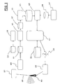
- Figure 1 a schematic block diagram is provided of a system according to an embodiment of the present invention.
- reference numeral 103 denotes a transceiver station of a wireless mobile communications network already deployed on the field, for example a BTS of a GSM network, or a Node-B of a UMTS network. It is intended that the wireless mobile communications network typically comprises several such transceiver stations, despite only one transceiver station is shown in the drawing for the sake of simplicity.
- the transceiver station 103 is connected, through a network connection 105, to a controller 107, which may for example be a BSC of a GSM network or an RNC (Radio Network Controller) of a UMTS network, and that controls the transceiver station 103 (and other similar transceiver stations).
- a controller 107 which may for example be a BSC of a GSM network or an RNC (Radio Network Controller) of a UMTS network, and that controls the transceiver station 103 (and other similar transceiver stations).
- Block 109 denotes transducers that are coupled to the network connection 105 and which are adapted to capture relevant network events, for example by exploiting hardware probes placed at the interface between the transceiver station 103 and the controller 107 (for example, the "Abis" interface, in the case of a GSM network).
- the captured network events may include for example calls drops, lost calls, network traffic, handovers from a cell to another, and are stored in a database 111 of network events to be geographically localized.
- the system comprises a geographic localization engine, adapted to derive the geographic localization of the captured network events.
- the geographic localization engine comprises a geographic localization client module 113, implemented for example in software, which is adapted to exploit the services provided by a geographic localization platform 115 in order to localize, i.e. assign a position to, the captured network events, providing as a result geographically-localized network events, which are then stored in a database 117.
- the geographic localization platform 115 includes a server software that implements a geographic localization algorithm; suitable geographic localization platforms are described for example in WO 2002/43428 and WO 2003/49479 , both in the name of the present Applicant; the geographic localization platform 115, exploiting network data 119 including the locations of the network's transceiver stations, their power, antennas' radiation patterns, and measures performed by the mobile terminals on the field and communicated to the network, is capable of accurately localizing the network events from the geographical viewpoint, for example in terms of area elements (pixels).
- a statistical indicators calculator 121 retrieves from the database 117 the geographically-localized network events, and processes them to derive statistical indicators; the statistical indicators derived by the statistical indicators calculator 121 include statistical indicators related to the different network cells (non-localized statistical indicators) and statistical indicators related to the geographic area elements (pixels) of the geographic area covered by the network (localized statistical indicators). The statistical indicators obtained are stored in a statistical indicators database 123.
- the statistical indicators calculator 121 includes several software modules, among which:
- the statistical indicators may be stored in the form of raster layers, i.e . territory maps, subdivided into area elements (pixels), e.g . each one corresponding to a square of 50 m by 50 m.
- a numerical value e.g. an integer
- Each raster layer in the statistical indicators database 123 i.e . the set of numerical values associated with the pixels of the territory represented by means of the raster layer, may be related to a respective time interval (day, week) and contains information related to a respective network event captured.
- the statistical indicators in the database 123 are exploited by a server, e.g. a software 125, which may in particular comprise a first module adapted to extract from the database 123 the statistical indicators, and a second module adapted to interface with a database 128 where data calculated by the automated network planning tool (schematically indicated as a block 137) are stored, to extract selected data therefrom.
- a server e.g. a software 125, which may in particular comprise a first module adapted to extract from the database 123 the statistical indicators, and a second module adapted to interface with a database 128 where data calculated by the automated network planning tool (schematically indicated as a block 137) are stored, to extract selected data therefrom.
- the database 128 is for example a relational database.
- the following data may in particular be stored in the database 128:
- the server software 125 interacts with and provides services to a diagnostic system 127.
- the diagnostic system 127 exploits the statistical indicators stored in the database 123 and provided thereto by the server software 125, together with information calculated by the automated network planning tool 137 and stored in the database 128; these data may for example include the network area coverage, lists of best servers in the respective geographic areas, Interference Matrices (IM).
- IM Interference Matrices
- the server software 125 may, in some practical embodiments of the present invention, be integrated in the network planning tool 137.
- the diagnostic system 127 is adapted to perform a diagnosis of the network status, and to generate diagnostic indicators useful to identify possible network criticalities.
- the diagnostic system 127 may comprise:
- the diagnostic system 127 may comprise an expert system that, based on the calculated diagnostic indicators, provides a list of network cells that exhibit criticalities, and the cause of such criticalities, like for example interference, area coverage, lost traffic.
- the diagnostic system 127 may comprise, in addition to the expert system, a network optimization tool, adapted to exploit the results provided by the expert system to determine the changes to be made to the network configuration.
- the expert system may provide to the network optimization tool a list of the network cells that exhibit criticalities, and the cells' parameters that may be changed for overcoming the criticalities; the network optimization tool optimizes the network configuration by determining the changes to be made to the cells' parameters indicated by the expert system in respect of the critical cells.
- the diagnostic indicators may be calculated exploiting, for each cell of the network, calls drops.
- the diagnostic indicators concerning problems of calls drops may include:
- the diagnostic indicators concerning problems of calls drops may include:
- the diagnostic indicators may also be differentiated based on the level of urbanization of the territory of that cell (exploiting the information included in the raster maps of the territory). For each cell, aggregated diagnostic indicators differentiated on the level of urbanization of the different pixels of the cells can also be provided.
- the diagnostic indicators may be calculated as described herebelow.
- the quantities in the database 128 are preferably normalized. Normalization may for example call for associating to the generic quantity a vote ranging for example from 0 to 10.
- the vote 0 is for example assigned to a range of values that are considered optimum for the corresponding quantity
- the vote 10 is assigned to a range of values for the considered quantity that is considered critical.
- high levels of the electromagnetic field are assigned a vote 0
- low levels of the electromagnetic field are assigned the vote 10 (obviously, other conventions, e.g . the opposite convention may be adopted).
- Intermediate votes describe situations intermediate between the optimum one and the critical one.
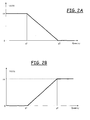
- Figures 2A to 2L depicts exemplary normalization, vote assignment functions that can be exploited to assign votes to the values of some of the quantities that may be present in the database 128.
- the normalizing function depicted in Figure 2A having a linearly decreasing trend down to a saturation value, can be used to assign a vote to the values of the quantity expressing the electromagnetic field level of the CPICH, which is reported in abscissa, and may be expressed in dBm; the thresholds g1 and g2 may for example be equal to -115 dBm and -46 dBm, respectively.
- the normalizing function depicted in Figure 2B having a linearly increasing trend up to a saturation value, can be used to assign a vote to the values of the quantity expressing the pilot pollution, which is reported in abscissa, and is expressed in terms of integer numbers; the thresholds g3 and g4 may for example be equal to 1 and 8, respectively.
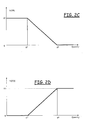
- the normalizing function depicted in Figure 2C having a linearly decreasing trend down to a saturation value, can be used to assign a vote to the values of the quantity expressing the Ec/Io, which is reported in abscissa, and is expressed in dB; the thresholds g5 and g6 may for example be equal to -18 dB and -12 dB, respectively.
- the normalizing function depicted in Figure 2D having a linearly increasing trend up to a saturation value, can be used to assign a vote to the values of the quantity expressing the power required to the mobile terminals in uplink, which is reported in abscissa, and is expressed in dBm; the thresholds g7 and g8 may for example be equal to -10 dBm and 18 dBm, respectively.
- the normalizing function depicted in Figure 2E having a linearly increasing trend up to a saturation value, can be used to assign a vote to the values of the quantity expressing the power required to the transceiver station in downlink, which is reported in abscissa, and is expressed in dBm; the thresholds g9 and g10 may for example be equal to 15 dBm and 33 dBm, respectively.
- the normalizing function depicted in Figure 2F having a linearly decreasing trend down to a saturation value, can be used to assign a vote to the values of the quantity expressing the power level of the BCCH, which is reported in abscissa, and is expressed in dBm; the thresholds g11 and g12 may for example be equal to -115 dBm and -46 dBm, respectively.
- the normalizing function depicted in Figure 2G having a linearly decreasing trend down to a saturation value, can be used to assign a vote to the values of the quantity expressing the C/I of the BCCH carrier, which is reported in abscissa, and is expressed in dB; the thresholds g13 and g14 may for example be equal to 12 dB and 16 dB, respectively.
- the normalizing function depicted in Figure 2H having a linearly decreasing trend down to a saturation value, can be used to assign a vote to the values of the quantity expressing the average C/I, which is reported in abscissa, and is expressed in dB; the thresholds g15 and g16 may for example be equal to 7 dB and 12 dB, respectively.
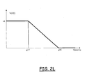
- the normalizing function depicted in Figure 2L having a linearly decreasing trend down to a saturation value, can be used to assign a vote to the values of the quantity expressing the worst C/I, which is reported in abscissa, and is expressed in dB; the thresholds g17 and g18 may for example be equal to 0 dB and 6 dB, respectively.
- Network events are captured by the transducers 109 and stored in the database 111 (block 305).
- the captured network events are geographically localized, exploiting the localization platform 115, and the geographically-localized network events are stored in the database 117 (block 310).
- the statistical indicators calculator 121 calculates statistical indicators in respect of the captured (and geographically localized) network events, and stores the calculated statistical indicators in the database 123 (block 315 ). In particular, statistical indicators related to calls drops are calculated.
- indications about the BCCH C/I are retrieved from the database 128 by the server 125 (block 320 ).
- a discretization of, in the considered example, the range of values within which the BCCH C/I can vary is done (block 325 ). This operation may be performed by the server 125, or by the diagnostic system 127.
- the range of values within which the BCCH C/I can vary is divided in sub-intervals, for example the following four C/I values intervals:
- a normalization process is then performed to assign to each sub-interval a respective vote in the range of votes from 0 to 10 (block 330 ); for example, using the function of Figure 2G , the vote assignment may be the following:
- the statistical indicators related to the measured calls drops are retrieved from the database 123 (block 335 ).
- a statistic of the experienced calls drops as a function of the BCCH C/I values is then calculated (block 340 ), for example by counting the number of measured calls drops that fall in each of the sub-intervals defined above for the BCCH C/I values. For example, let it be assumed that, in the generic network cell, the number of calls drops that fall in the first sub-interval of the BCCH C/I values (having been assigned vote 10) is 80, the number of calls drops that fall in the second sub-interval (having been assigned vote 7) is 23, the number of calls drops that fall in the third sub-interval (having been assigned vote 2) is 12, and the number of calls drops that fall in the fourth sub-interval (having been assigned vote 0) is 3.
- the above formula gives, in the example herein considered, a value of 8.34, indicating a high degree of correlation between low C/I values and number of calls drops measured in the area of the generic cell j.
- the diagnostic indicators calculated by the module 127 provides an indication of the degree of correlation between the measured network events and network characteristics obtained by simulating the network using an automated network planning tool.
- the value ID j ( sim_data,stat_ind ) may also be calculated differentiated on the basis of the level of urbanization in the different area portions of the considered network cell j, and possibly restricted to a selected time interval.
- a more general form of the generic diagnostic indicator may be the following: ID j ( sim_data i ,stat_ind k ,Class l ,t ), where Class identifies the level of urbanization, and t identifies a time interval.
- the diagnostic indicators calculated by the module 127 are stored in a database 131 (block 345).
- the (expert system of the) diagnostic module 127 may provide a list of network cells that exhibit criticalities, and whose parameters should be upgraded (350).
- the network optimization tool of the module 127 determines the changes to be made to the critical cells' parameters.
- actuators 135 are provided that interact with the network equipments.
- the expert system, or the network optimization tool of the diagnostic module 127 might also directly send to the actuators the instructions for implementing the upgrades suitable to overcome the detected network criticalities. Also, the expert system of the diagnostic module 127 may learn from previous actions undertaken to overcome network criticalities detected in the past.
- the configuration (i.e. cells' parameters) of the wireless communications network is then upgraded (block 355).
Landscapes
- Engineering & Computer Science (AREA)
- Computer Networks & Wireless Communication (AREA)
- Signal Processing (AREA)
- Mobile Radio Communication Systems (AREA)
Claims (14)
- Procédé de mise à niveau d'un réseau de communication mobile sans fil déployé sur place, comprenant :- l'obtention de données de simulation de réseau d'une configuration de réseau actuelle à partir d'un outil de planification de simulation de réseau automatisé (137, 320) ;- le captage d'événements de réseau à partir du réseau de communication mobile sans fil (305), dans lequel les événements de réseau captés sont connexes à des mesures concernant des paramètres de réseau identiques à ceux des données de simulation de réseau ;- la localisation, dans la zone géographique couverte par le réseau de communication mobile sans fil, des événements de réseau captés (310) ;- en utilisant les événements de réseau captés localisés géographiquement, le calcul (315) d'indicateurs statistiques d'événements de réseau en fonction des événements de réseau captés localisés géographiquement (315),- la combinaison des indicateurs statistiques d'événements de réseau calculés et des données de simulation de réseau pour dériver des indicateurs diagnostiques adaptés à des caractères critiques d'indication dans une configuration de réseau actuelle (325-350), dans lequel ladite combinaison comprend le calcul de degrés de corrélation entre les événements de réseau captés et les données de simulation de réseau ;- en fonction des indicateurs diagnostiques ainsi dérivés, la détermination de changements devant être apportés à la configuration de réseau actuelle pour résoudre les caractères critiques ; et- la modification (355) de la configuration de réseau actuelle en mettant en oeuvre lesdits changements pour résoudre les caractères critiques (355).
- Procédé selon la revendication 1, dans lequel ladite localisation des événements de réseau captés comprend la détermination d'une zone élémentaire d'une zone géographique couverte par le réseau de communication mobile sans fil dans laquelle les événements de réseau captés se sont produits.
- Procédé selon la revendication 1 ou 2, dans lequel ledit calcul de degrés de corrélation comprend la discrétisation (325) et la normalisation (330) de valeurs desdites données de simulation de réseau.
- Procédé selon une quelconque des revendications précédentes, dans lequel lesdits événements de réseau comprennent un ou plusieurs parmi des abandons d'appels, des appels perdus, un trafic de réseau, des transferts d'une cellule à une autre.
- Procédé selon une quelconque des revendications précédentes, dans lequel lesdits indicateurs diagnostiques sont calculés en ce qui concerne des éléments de zone d'une zone géographique couverte par le réseau de communication mobile sans fil.
- Procédé selon la revendication 5, dans lequel lesdits indicateurs diagnostiques sont différentiés en fonction d'une indication d'un niveau d'urbanisation d'une zone couverte par le réseau de communication mobile sans fil.
- Procédé selon la revendication 6, dans lequel des indicateurs diagnostiques agrégés en ce qui concerne des zones couvertes par des cellules de réseau sont calculés.
- Système pour mettre à niveau un réseau de communication mobile sans fil déployé sur place, comprenant :- un outil de planification de simulation de réseau automatisé (137) adapté pour calculer des données de simulation de réseau ;- des transducteurs (109) adaptés pour capturer des événements de réseau à partir du réseau de communication mobile sans fil ;- une plateforme de localisation (115) adaptée pour localiser, dans la zone géographique couverte par le réseau de communication mobile sans fil, les événements de réseau captés ;- un calculateur d'indicateurs statistiques (121) adapté pour calculer des indicateurs statistiques d'événements de réseau en fonction des événements de réseau captés localisés géographiquement,- un système diagnostique (127) adapté pour combiner, en calculant des degrés de corrélation, les indicateurs statistiques d'événements de réseau et les données de simulation de réseau pour dériver des indicateurs diagnostiques adaptés à des caractères critiques d'indication dans une configuration de réseau actuelle, dans lequel ledit système diagnostique est en outre adapté pour déterminer des changements devant être apportés à la configuration de réseau actuelle pour résoudre les caractères critiques ; et- des actionneurs (135) adaptés pour interagir avec les équipements de réseau pour faire en sorte que la configuration de réseau actuelle soit modifiée pour résoudre les caractères critiques.
- Système selon la revendication 8, dans lequel ladite plateforme de localisation est adaptée pour déterminer une zone élémentaire de la zone géographique couverte par le réseau de communication mobile sans fil dans laquelle les événements de réseau captés se sont produits.
- Système selon la revendication 8 ou 9, dans lequel ledit calcul de degrés de corrélation comprend la discrétisation (325) et la normalisation (330) de valeurs desdites données de simulation de réseau.
- Système selon une quelconque des revendications 8 à 10, dans lequel lesdits événements de réseau comprennent un ou plusieurs parmi des abandons d'appels, des appels perdus, un trafic de réseau, des transferts d'une cellule à une autre.
- Système selon une quelconque des revendications 8 à 11, dans lequel lesdits indicateurs diagnostiques sont calculés en ce qui concerne des éléments de zone d'une zone géographique couverte par le réseau de communication mobile sans fil.
- Système selon la revendication 12, dans lequel lesdits indicateurs diagnostiques sont différentiés en fonction d'une indication d'un niveau d'urbanisation d'une zone couverte par le réseau de communication mobile sans fil.
- Système selon la revendication 13, dans lequel des indicateurs diagnostiques agrégés en ce qui concerne des zones couvertes par des cellules de réseau sont calculés.
Applications Claiming Priority (1)
| Application Number | Priority Date | Filing Date | Title |
|---|---|---|---|
| PCT/EP2007/064649 WO2009083035A1 (fr) | 2007-12-31 | 2007-12-31 | Procédé et système d'optimisation de la configuration d'un réseau de communications sans fil |
Publications (2)
| Publication Number | Publication Date |
|---|---|
| EP2250832A1 EP2250832A1 (fr) | 2010-11-17 |
| EP2250832B1 true EP2250832B1 (fr) | 2015-07-01 |
Family
ID=39714071
Family Applications (1)
| Application Number | Title | Priority Date | Filing Date |
|---|---|---|---|
| EP07858235.0A Active EP2250832B1 (fr) | 2007-12-31 | 2007-12-31 | Procédé et système d'optimisation de la configuration d'un réseau de communications sans fil |
Country Status (4)
| Country | Link |
|---|---|
| US (1) | US9088900B2 (fr) |
| EP (1) | EP2250832B1 (fr) |
| BR (1) | BRPI0722328B1 (fr) |
| WO (1) | WO2009083035A1 (fr) |
Families Citing this family (18)
| Publication number | Priority date | Publication date | Assignee | Title |
|---|---|---|---|---|
| JP4787792B2 (ja) * | 2007-06-18 | 2011-10-05 | 株式会社エヌ・ティ・ティ・ドコモ | 無線制御装置、無線通信システム、通信路設定方法 |
| US8868452B2 (en) * | 2008-05-01 | 2014-10-21 | Accenture Global Services Limited | Smart grid deployment simulator |
| EP2695328B1 (fr) * | 2011-04-07 | 2019-10-09 | Nokia Solutions and Networks Oy | Optimisation de la configuration du réseau |
| FI20115857A0 (fi) * | 2011-09-01 | 2011-09-01 | Omnitele Ab Oy | Älykäs kapasiteetin hallinta |
| EP2621210B1 (fr) * | 2012-01-27 | 2014-01-22 | Alcatel Lucent | Procédé pour déterminer les paramètres de configuration de cellule dans un réseau de télécommunication sans fil |
| EP2645631B1 (fr) * | 2012-03-26 | 2018-11-21 | Tata Consultancy Services Limited | Procédé et système permettant d'automatiser l'optimisation d'un réseau d'entreprise |
| EP2779731B1 (fr) * | 2013-03-15 | 2015-10-21 | Alcatel Lucent | Commande de réseau |
| AU2013202164B2 (en) * | 2013-03-28 | 2016-05-12 | Robert Bosch (Australia) Pty Ltd | Method for determining the location of a remote transmitter positioned near a vehicle |
| CN104270769B (zh) * | 2014-09-28 | 2018-03-06 | 中国联合网络通信集团有限公司 | 基站选址的方法及装置 |
| US20190021012A1 (en) * | 2017-07-12 | 2019-01-17 | Commscope Technologies Llc | Method and system for rf planning in a dynamic spectrum environment |
| CN109936851B (zh) * | 2017-12-15 | 2021-11-30 | 中国移动通信集团浙江有限公司 | Lte网络指标处理方法及装置 |
| CN108200599A (zh) * | 2018-03-29 | 2018-06-22 | 中国联合网络通信集团有限公司 | 一种基站的效能评价方法、装置及网络系统 |
| EP3609213B1 (fr) * | 2018-08-06 | 2022-07-13 | Deutsche Telekom AG | Procédé de conception géométrique des zones de voisinage des emplacements de l'équipement de téléphonie mobile dans un réseau de téléphonie mobile |
| US11711709B2 (en) | 2018-08-23 | 2023-07-25 | Tracfone Wireless, Inc. | System and process for using cellular connectivity analysis to determine optimal wireless equipment and service for a geographical area |
| US11323890B2 (en) * | 2019-07-10 | 2022-05-03 | At&T Intellectual Property I, L.P. | Integrated mobility network planning |
| US11805541B2 (en) | 2020-06-17 | 2023-10-31 | Commscope Technologies Llc | Methods and systems for provisioning of parameter data of radios controlled by a spectrum access system |
| US12593221B2 (en) * | 2022-02-24 | 2026-03-31 | Shimano Inc. | Wireless communication device for human-powered vehicle |
| US12108260B2 (en) | 2022-04-27 | 2024-10-01 | At&T Intellectual Property I, L.P. | Integrated network deployment tool |
Family Cites Families (14)
| Publication number | Priority date | Publication date | Assignee | Title |
|---|---|---|---|---|
| US6085335A (en) * | 1997-10-02 | 2000-07-04 | Nortel Networks Limited | Self engineering system for use with a communication system and method of operation therefore |
| US6141565A (en) * | 1997-11-13 | 2000-10-31 | Metawave Communications Corporation | Dynamic mobile parameter optimization |
| US6522888B1 (en) * | 1999-08-31 | 2003-02-18 | Lucent Technologies Inc. | System for determining wireless coverage using location information for a wireless unit |
| US6971063B1 (en) * | 2000-07-28 | 2005-11-29 | Wireless Valley Communications Inc. | System, method, and apparatus for portable design, deployment, test, and optimization of a communication network |
| IT1316567B1 (it) | 2000-08-01 | 2003-04-24 | Simtel Srl | Sistema per il controllo della qualita' di funzionamento di reti ditelefonia mobile. |
| IT1320733B1 (it) * | 2000-10-27 | 2003-12-10 | Cselt Centro Studi Lab Telecom | Sistema e metodo per la pianificazione di una rete per apparecchiature mobili di telecomunicazioni. |
| IT1321086B1 (it) | 2000-11-24 | 2003-12-30 | Cselt Centro Studi Lab Telecom | Sistema e metodo per individuare la posizione di apparecchiaturemobili |
| ITTO20011125A1 (it) | 2001-12-03 | 2003-06-03 | Telecom Italia Lab Spa | Sistema e metodo per individuare la posizione di terminali mibili. |
| US20030186693A1 (en) * | 2002-04-01 | 2003-10-02 | Gil Shafran | Estimating traffic distribution in a mobile communication network |
| FI20030998A0 (fi) * | 2003-07-02 | 2003-07-02 | Nokia Corp | Verkkomittaukset radiotelekommunikaatioverkossa |
| US20050288009A1 (en) * | 2004-06-28 | 2005-12-29 | Mark Poletti | Method and apparatus for objective measurement of wireless service performance and coverage |
| US7818150B2 (en) * | 2005-03-11 | 2010-10-19 | Hyperformix, Inc. | Method for building enterprise scalability models from load test and trace test data |
| EP1718089A1 (fr) * | 2005-04-29 | 2006-11-02 | Siemens S.p.A. | Procédé d'analyse de paramètres opérationels dépendants du trafic dans un système de communication cellulaire, système correspondant et produit de programme d'ordinateur |
| WO2007071271A1 (fr) * | 2005-12-21 | 2007-06-28 | Telecom Italia S.P.A. | Procede d'estimation de couverture radioelectrique de zone geographique dans un reseau cellulaire de radiocommunications mobiles |
-
2007
- 2007-12-31 US US12/811,228 patent/US9088900B2/en active Active
- 2007-12-31 BR BRPI0722328A patent/BRPI0722328B1/pt active IP Right Grant
- 2007-12-31 EP EP07858235.0A patent/EP2250832B1/fr active Active
- 2007-12-31 WO PCT/EP2007/064649 patent/WO2009083035A1/fr not_active Ceased
Also Published As
| Publication number | Publication date |
|---|---|
| EP2250832A1 (fr) | 2010-11-17 |
| US9088900B2 (en) | 2015-07-21 |
| US20100285788A1 (en) | 2010-11-11 |
| BRPI0722328A2 (pt) | 2014-04-08 |
| BRPI0722328B1 (pt) | 2020-01-21 |
| WO2009083035A1 (fr) | 2009-07-09 |
Similar Documents
| Publication | Publication Date | Title |
|---|---|---|
| EP2250832B1 (fr) | Procédé et système d'optimisation de la configuration d'un réseau de communications sans fil | |
| US11310676B2 (en) | Methods for mitigating interference and maximizing capacity for time division duplex cellular networks | |
| US11018784B2 (en) | Detecting tropospheric ducting interference in cellular networks | |
| US5023900A (en) | Cellular radiotelephone diagnostic system | |
| US7853267B2 (en) | Wireless system signal propagation collection and analysis | |
| US6466797B1 (en) | Methods and arrangements relating to a radio communication system | |
| KR101565350B1 (ko) | 무선 네트워크의 커버리지 영역에서 동작 파라미터를 매핑시키기 위한 방법 및 장치 | |
| US6985745B2 (en) | Method and radio signature position determining entity (RS-PDE) for maintaining location database reliability | |
| US20110130135A1 (en) | Coverage hole detector | |
| US20040203717A1 (en) | Method, system and radio network management functionality for radio data mapping to physical location in a cellular telecommunications network | |
| CN103906109B (zh) | 一种移动通信系统干扰排查方法和装置 | |
| EP2429228A1 (fr) | Système de gestion de réseau, procédé de contrôle de couverture sans fil, et programme de contrôle de couverture sans fil | |
| CN108718254B (zh) | 地铁室内分布系统故障定位方法及系统 | |
| EP1829403B1 (fr) | Procedes et systemes destines a l'estimation de la couverture ascendante dans des reseaux de telecommunications sans fil avec une couverture dynamique de cellules | |
| CN101621808B (zh) | 一种确定小区覆盖范围的方法和装置 | |
| US8219074B2 (en) | Method and apparatus for communication site planning | |
| CN116132999B (zh) | 一种识别室内分布系统局部异常的方法及其装置 | |
| US6393277B1 (en) | System and method for identifying a source of interference in a mobile telecommunications network | |
| KR101764663B1 (ko) | 비이온화 방사선 소스의 온라인 방사선 관리 및 제어의 시스템 및 방법 | |
| Jovanovic et al. | Analysis of mobile phone geolocation methods used in US courts | |
| KR20030046905A (ko) | 이동 통신 시스템에서의 호 접속실패 원인 분석 방법 | |
| CN1778131A (zh) | 用于测试移动电话网络的系统和方法 | |
| Brown et al. | Geospatial analysis of future spectrum requirements for 5G FWA systems | |
| CN109041102B (zh) | 一种蜂窝式频率评估系统及频率评估方法 | |
| EP1647157B1 (fr) | Procede permettant de determiner une charge de trafic geographique dans un reseau de telecommunications mobiles |
Legal Events
| Date | Code | Title | Description |
|---|---|---|---|
| PUAI | Public reference made under article 153(3) epc to a published international application that has entered the european phase |
Free format text: ORIGINAL CODE: 0009012 |
|
| 17P | Request for examination filed |
Effective date: 20100730 |
|
| AK | Designated contracting states |
Kind code of ref document: A1 Designated state(s): AT BE BG CH CY CZ DE DK EE ES FI FR GB GR HU IE IS IT LI LT LU LV MC MT NL PL PT RO SE SI SK TR |
|
| AX | Request for extension of the european patent |
Extension state: AL BA HR MK RS |
|
| 17Q | First examination report despatched |
Effective date: 20110121 |
|
| DAX | Request for extension of the european patent (deleted) | ||
| REG | Reference to a national code |
Ref country code: DE Ref legal event code: R079 Ref document number: 602007041983 Country of ref document: DE Free format text: PREVIOUS MAIN CLASS: H04W0024000000 Ipc: H04W0024020000 |
|
| GRAP | Despatch of communication of intention to grant a patent |
Free format text: ORIGINAL CODE: EPIDOSNIGR1 |
|
| RIC1 | Information provided on ipc code assigned before grant |
Ipc: H04W 24/06 20090101ALN20150206BHEP Ipc: H04W 24/02 20090101AFI20150206BHEP Ipc: H04W 16/18 20090101ALN20150206BHEP |
|
| RIC1 | Information provided on ipc code assigned before grant |
Ipc: H04W 24/02 20090101AFI20150226BHEP Ipc: H04W 16/18 20090101ALN20150226BHEP Ipc: H04W 24/06 20090101ALN20150226BHEP |
|
| INTG | Intention to grant announced |
Effective date: 20150309 |
|
| GRAS | Grant fee paid |
Free format text: ORIGINAL CODE: EPIDOSNIGR3 |
|
| GRAA | (expected) grant |
Free format text: ORIGINAL CODE: 0009210 |
|
| RAP1 | Party data changed (applicant data changed or rights of an application transferred) |
Owner name: TELECOM ITALIA S.P.A. |
|
| AK | Designated contracting states |
Kind code of ref document: B1 Designated state(s): AT BE BG CH CY CZ DE DK EE ES FI FR GB GR HU IE IS IT LI LT LU LV MC MT NL PL PT RO SE SI SK TR |
|
| REG | Reference to a national code |
Ref country code: GB Ref legal event code: FG4D |
|
| REG | Reference to a national code |
Ref country code: AT Ref legal event code: REF Ref document number: 734582 Country of ref document: AT Kind code of ref document: T Effective date: 20150715 Ref country code: CH Ref legal event code: EP |
|
| REG | Reference to a national code |
Ref country code: IE Ref legal event code: FG4D |
|
| REG | Reference to a national code |
Ref country code: DE Ref legal event code: R096 Ref document number: 602007041983 Country of ref document: DE |
|
| REG | Reference to a national code |
Ref country code: AT Ref legal event code: MK05 Ref document number: 734582 Country of ref document: AT Kind code of ref document: T Effective date: 20150701 |
|
| REG | Reference to a national code |
Ref country code: NL Ref legal event code: MP Effective date: 20150701 |
|
| REG | Reference to a national code |
Ref country code: FR Ref legal event code: PLFP Year of fee payment: 9 |
|
| REG | Reference to a national code |
Ref country code: LT Ref legal event code: MG4D |
|
| PG25 | Lapsed in a contracting state [announced via postgrant information from national office to epo] |
Ref country code: FI Free format text: LAPSE BECAUSE OF FAILURE TO SUBMIT A TRANSLATION OF THE DESCRIPTION OR TO PAY THE FEE WITHIN THE PRESCRIBED TIME-LIMIT Effective date: 20150701 Ref country code: LV Free format text: LAPSE BECAUSE OF FAILURE TO SUBMIT A TRANSLATION OF THE DESCRIPTION OR TO PAY THE FEE WITHIN THE PRESCRIBED TIME-LIMIT Effective date: 20150701 Ref country code: GR Free format text: LAPSE BECAUSE OF FAILURE TO SUBMIT A TRANSLATION OF THE DESCRIPTION OR TO PAY THE FEE WITHIN THE PRESCRIBED TIME-LIMIT Effective date: 20151002 Ref country code: LT Free format text: LAPSE BECAUSE OF FAILURE TO SUBMIT A TRANSLATION OF THE DESCRIPTION OR TO PAY THE FEE WITHIN THE PRESCRIBED TIME-LIMIT Effective date: 20150701 |
|
| PG25 | Lapsed in a contracting state [announced via postgrant information from national office to epo] |
Ref country code: PT Free format text: LAPSE BECAUSE OF FAILURE TO SUBMIT A TRANSLATION OF THE DESCRIPTION OR TO PAY THE FEE WITHIN THE PRESCRIBED TIME-LIMIT Effective date: 20151102 Ref country code: PL Free format text: LAPSE BECAUSE OF FAILURE TO SUBMIT A TRANSLATION OF THE DESCRIPTION OR TO PAY THE FEE WITHIN THE PRESCRIBED TIME-LIMIT Effective date: 20150701 Ref country code: SE Free format text: LAPSE BECAUSE OF FAILURE TO SUBMIT A TRANSLATION OF THE DESCRIPTION OR TO PAY THE FEE WITHIN THE PRESCRIBED TIME-LIMIT Effective date: 20150701 Ref country code: IS Free format text: LAPSE BECAUSE OF FAILURE TO SUBMIT A TRANSLATION OF THE DESCRIPTION OR TO PAY THE FEE WITHIN THE PRESCRIBED TIME-LIMIT Effective date: 20151101 Ref country code: AT Free format text: LAPSE BECAUSE OF FAILURE TO SUBMIT A TRANSLATION OF THE DESCRIPTION OR TO PAY THE FEE WITHIN THE PRESCRIBED TIME-LIMIT Effective date: 20150701 Ref country code: ES Free format text: LAPSE BECAUSE OF FAILURE TO SUBMIT A TRANSLATION OF THE DESCRIPTION OR TO PAY THE FEE WITHIN THE PRESCRIBED TIME-LIMIT Effective date: 20150701 |
|
| REG | Reference to a national code |
Ref country code: DE Ref legal event code: R097 Ref document number: 602007041983 Country of ref document: DE |
|
| PG25 | Lapsed in a contracting state [announced via postgrant information from national office to epo] |
Ref country code: SK Free format text: LAPSE BECAUSE OF FAILURE TO SUBMIT A TRANSLATION OF THE DESCRIPTION OR TO PAY THE FEE WITHIN THE PRESCRIBED TIME-LIMIT Effective date: 20150701 Ref country code: DK Free format text: LAPSE BECAUSE OF FAILURE TO SUBMIT A TRANSLATION OF THE DESCRIPTION OR TO PAY THE FEE WITHIN THE PRESCRIBED TIME-LIMIT Effective date: 20150701 Ref country code: EE Free format text: LAPSE BECAUSE OF FAILURE TO SUBMIT A TRANSLATION OF THE DESCRIPTION OR TO PAY THE FEE WITHIN THE PRESCRIBED TIME-LIMIT Effective date: 20150701 Ref country code: CZ Free format text: LAPSE BECAUSE OF FAILURE TO SUBMIT A TRANSLATION OF THE DESCRIPTION OR TO PAY THE FEE WITHIN THE PRESCRIBED TIME-LIMIT Effective date: 20150701 |
|
| PLBE | No opposition filed within time limit |
Free format text: ORIGINAL CODE: 0009261 |
|
| STAA | Information on the status of an ep patent application or granted ep patent |
Free format text: STATUS: NO OPPOSITION FILED WITHIN TIME LIMIT |
|
| PG25 | Lapsed in a contracting state [announced via postgrant information from national office to epo] |
Ref country code: RO Free format text: LAPSE BECAUSE OF FAILURE TO SUBMIT A TRANSLATION OF THE DESCRIPTION OR TO PAY THE FEE WITHIN THE PRESCRIBED TIME-LIMIT Effective date: 20150701 Ref country code: BE Free format text: LAPSE BECAUSE OF NON-PAYMENT OF DUE FEES Effective date: 20151231 |
|
| 26N | No opposition filed |
Effective date: 20160404 |
|
| PG25 | Lapsed in a contracting state [announced via postgrant information from national office to epo] |
Ref country code: LU Free format text: LAPSE BECAUSE OF FAILURE TO SUBMIT A TRANSLATION OF THE DESCRIPTION OR TO PAY THE FEE WITHIN THE PRESCRIBED TIME-LIMIT Effective date: 20151231 Ref country code: MC Free format text: LAPSE BECAUSE OF FAILURE TO SUBMIT A TRANSLATION OF THE DESCRIPTION OR TO PAY THE FEE WITHIN THE PRESCRIBED TIME-LIMIT Effective date: 20150701 |
|
| REG | Reference to a national code |
Ref country code: CH Ref legal event code: PL |
|
| PG25 | Lapsed in a contracting state [announced via postgrant information from national office to epo] |
Ref country code: SI Free format text: LAPSE BECAUSE OF FAILURE TO SUBMIT A TRANSLATION OF THE DESCRIPTION OR TO PAY THE FEE WITHIN THE PRESCRIBED TIME-LIMIT Effective date: 20150701 |
|
| REG | Reference to a national code |
Ref country code: IE Ref legal event code: MM4A |
|
| PG25 | Lapsed in a contracting state [announced via postgrant information from national office to epo] |
Ref country code: LI Free format text: LAPSE BECAUSE OF NON-PAYMENT OF DUE FEES Effective date: 20151231 Ref country code: CH Free format text: LAPSE BECAUSE OF NON-PAYMENT OF DUE FEES Effective date: 20151231 Ref country code: IE Free format text: LAPSE BECAUSE OF NON-PAYMENT OF DUE FEES Effective date: 20151231 |
|
| REG | Reference to a national code |
Ref country code: FR Ref legal event code: PLFP Year of fee payment: 10 |
|
| PG25 | Lapsed in a contracting state [announced via postgrant information from national office to epo] |
Ref country code: BE Free format text: LAPSE BECAUSE OF FAILURE TO SUBMIT A TRANSLATION OF THE DESCRIPTION OR TO PAY THE FEE WITHIN THE PRESCRIBED TIME-LIMIT Effective date: 20150701 |
|
| PG25 | Lapsed in a contracting state [announced via postgrant information from national office to epo] |
Ref country code: IT Free format text: LAPSE BECAUSE OF NON-PAYMENT OF DUE FEES Effective date: 20151231 |
|
| PG25 | Lapsed in a contracting state [announced via postgrant information from national office to epo] |
Ref country code: HU Free format text: LAPSE BECAUSE OF FAILURE TO SUBMIT A TRANSLATION OF THE DESCRIPTION OR TO PAY THE FEE WITHIN THE PRESCRIBED TIME-LIMIT; INVALID AB INITIO Effective date: 20071231 Ref country code: BG Free format text: LAPSE BECAUSE OF FAILURE TO SUBMIT A TRANSLATION OF THE DESCRIPTION OR TO PAY THE FEE WITHIN THE PRESCRIBED TIME-LIMIT Effective date: 20150701 |
|
| PG25 | Lapsed in a contracting state [announced via postgrant information from national office to epo] |
Ref country code: CY Free format text: LAPSE BECAUSE OF FAILURE TO SUBMIT A TRANSLATION OF THE DESCRIPTION OR TO PAY THE FEE WITHIN THE PRESCRIBED TIME-LIMIT Effective date: 20150701 Ref country code: NL Free format text: LAPSE BECAUSE OF FAILURE TO SUBMIT A TRANSLATION OF THE DESCRIPTION OR TO PAY THE FEE WITHIN THE PRESCRIBED TIME-LIMIT Effective date: 20150701 |
|
| PG25 | Lapsed in a contracting state [announced via postgrant information from national office to epo] |
Ref country code: MT Free format text: LAPSE BECAUSE OF FAILURE TO SUBMIT A TRANSLATION OF THE DESCRIPTION OR TO PAY THE FEE WITHIN THE PRESCRIBED TIME-LIMIT Effective date: 20150701 Ref country code: IT Free format text: LAPSE BECAUSE OF NON-PAYMENT OF DUE FEES Effective date: 20151231 |
|
| PGRI | Patent reinstated in contracting state [announced from national office to epo] |
Ref country code: IT Effective date: 20170710 |
|
| REG | Reference to a national code |
Ref country code: FR Ref legal event code: PLFP Year of fee payment: 11 |
|
| P01 | Opt-out of the competence of the unified patent court (upc) registered |
Effective date: 20230529 |
|
| P02 | Opt-out of the competence of the unified patent court (upc) changed |
Effective date: 20230604 |
|
| PGFP | Annual fee paid to national office [announced via postgrant information from national office to epo] |
Ref country code: GB Payment date: 20251229 Year of fee payment: 19 |
|
| PGFP | Annual fee paid to national office [announced via postgrant information from national office to epo] |
Ref country code: FR Payment date: 20251222 Year of fee payment: 19 |
|
| PGFP | Annual fee paid to national office [announced via postgrant information from national office to epo] |
Ref country code: TR Payment date: 20251224 Year of fee payment: 19 |
|
| PGFP | Annual fee paid to national office [announced via postgrant information from national office to epo] |
Ref country code: DE Payment date: 20251222 Year of fee payment: 19 |
|
| PGFP | Annual fee paid to national office [announced via postgrant information from national office to epo] |
Ref country code: IT Payment date: 20251231 Year of fee payment: 19 |