EP2250926A2 - Assemblage de plaques et leur préparation - Google Patents
Assemblage de plaques et leur préparation Download PDFInfo
- Publication number
- EP2250926A2 EP2250926A2 EP20100003175 EP10003175A EP2250926A2 EP 2250926 A2 EP2250926 A2 EP 2250926A2 EP 20100003175 EP20100003175 EP 20100003175 EP 10003175 A EP10003175 A EP 10003175A EP 2250926 A2 EP2250926 A2 EP 2250926A2
- Authority
- EP
- European Patent Office
- Prior art keywords
- plate
- slot
- width
- narrow side
- material thickness
- Prior art date
- Legal status (The legal status is an assumption and is not a legal conclusion. Google has not performed a legal analysis and makes no representation as to the accuracy of the status listed.)
- Withdrawn
Links
- 238000004519 manufacturing process Methods 0.000 title description 5
- 238000005304 joining Methods 0.000 title description 2
- 239000000463 material Substances 0.000 claims abstract description 38
- 238000000034 method Methods 0.000 claims abstract description 10
- 230000000149 penetrating effect Effects 0.000 claims description 5
- 239000002023 wood Substances 0.000 claims description 5
- 230000000284 resting effect Effects 0.000 claims description 2
- 150000001875 compounds Chemical class 0.000 description 6
- 238000003801 milling Methods 0.000 description 5
- 238000005553 drilling Methods 0.000 description 3
- 239000002131 composite material Substances 0.000 description 2
- 238000003780 insertion Methods 0.000 description 2
- 230000037431 insertion Effects 0.000 description 2
- 125000006850 spacer group Chemical group 0.000 description 2
- 239000006228 supernatant Substances 0.000 description 2
- XLYOFNOQVPJJNP-UHFFFAOYSA-N water Substances O XLYOFNOQVPJJNP-UHFFFAOYSA-N 0.000 description 2
- 238000010276 construction Methods 0.000 description 1
- 239000006260 foam Substances 0.000 description 1
- 230000001771 impaired effect Effects 0.000 description 1
- 238000009776 industrial production Methods 0.000 description 1
- 230000003287 optical effect Effects 0.000 description 1
- 238000004806 packaging method and process Methods 0.000 description 1
- 230000002093 peripheral effect Effects 0.000 description 1
- 230000035939 shock Effects 0.000 description 1
- 238000003860 storage Methods 0.000 description 1
Images


Classifications
-
- A—HUMAN NECESSITIES
- A47—FURNITURE; DOMESTIC ARTICLES OR APPLIANCES; COFFEE MILLS; SPICE MILLS; SUCTION CLEANERS IN GENERAL
- A47B—TABLES; DESKS; OFFICE FURNITURE; CABINETS; DRAWERS; GENERAL DETAILS OF FURNITURE
- A47B47/00—Cabinets, racks or shelf units, characterised by features related to dismountability or building-up from elements
- A47B47/04—Cabinets, racks or shelf units, characterised by features related to dismountability or building-up from elements made mainly of wood or plastics
- A47B47/042—Panels connected without frames
-
- F—MECHANICAL ENGINEERING; LIGHTING; HEATING; WEAPONS; BLASTING
- F16—ENGINEERING ELEMENTS AND UNITS; GENERAL MEASURES FOR PRODUCING AND MAINTAINING EFFECTIVE FUNCTIONING OF MACHINES OR INSTALLATIONS; THERMAL INSULATION IN GENERAL
- F16B—DEVICES FOR FASTENING OR SECURING CONSTRUCTIONAL ELEMENTS OR MACHINE PARTS TOGETHER, e.g. NAILS, BOLTS, CIRCLIPS, CLAMPS, CLIPS OR WEDGES; JOINTS OR JOINTING
- F16B12/00—Jointing of furniture or the like, e.g. hidden from exterior
- F16B12/10—Jointing of furniture or the like, e.g. hidden from exterior using pegs, bolts, tenons, clamps, clips, or the like
- F16B12/12—Jointing of furniture or the like, e.g. hidden from exterior using pegs, bolts, tenons, clamps, clips, or the like for non-metal furniture parts, e.g. made of wood, of plastics
- F16B12/125—Jointing of furniture or the like, e.g. hidden from exterior using pegs, bolts, tenons, clamps, clips, or the like for non-metal furniture parts, e.g. made of wood, of plastics using mortise and tenon joints
-
- A—HUMAN NECESSITIES
- A47—FURNITURE; DOMESTIC ARTICLES OR APPLIANCES; COFFEE MILLS; SPICE MILLS; SUCTION CLEANERS IN GENERAL
- A47B—TABLES; DESKS; OFFICE FURNITURE; CABINETS; DRAWERS; GENERAL DETAILS OF FURNITURE
- A47B2230/00—Furniture jointing; Furniture with such jointing
- A47B2230/0074—Mortise and tenon joints or the like including some general male and female connections
- A47B2230/0085—Mutually slotted furniture joints
-
- A—HUMAN NECESSITIES
- A47—FURNITURE; DOMESTIC ARTICLES OR APPLIANCES; COFFEE MILLS; SPICE MILLS; SUCTION CLEANERS IN GENERAL
- A47B—TABLES; DESKS; OFFICE FURNITURE; CABINETS; DRAWERS; GENERAL DETAILS OF FURNITURE
- A47B2230/00—Furniture jointing; Furniture with such jointing
- A47B2230/0074—Mortise and tenon joints or the like including some general male and female connections
- A47B2230/0085—Mutually slotted furniture joints
- A47B2230/0088—Mutually slotted furniture joints for table frames or frames with cut-out leg sections which retain the slotted joints
Definitions
- the invention relates to a method for producing a connection between two mutually perpendicular, penetrating plates and in a further embodiment a screw connection of two narrow side arranged on flat side, perpendicular to each other plates.
- Wood joints have long been known and proven in many forms. In addition to the techniques of Studentsblattens find as positive connections in particular those use that rely on the principle of groove and tenon.
- Such groove and tenon joints allow a narrow-side connection of plates to each other, for example in planks, panels, laminates or the like.
- cross-overlapping can be used, in which the two plates are provided with corresponding slots.
- the invention has the object to allow a combination of two mutually perpendicular, penetrating plates that can be assembled without tools, can be easily and quickly produced and can also be easily disassembled, with a long life a wear should be minimized.
- connection of the plates should be made extremely accurate to achieve a high mechanical stability. This is independent of dimensional tolerances in the material thickness of the plates used, even in industrial production.
- a slot with parallel slot walls is milled from a narrow side of a first plate, wherein the axis of rotation of the cutter is perpendicular to the plate.
- the width of the slot is dimensioned smaller than the material thickness of the second plate.
- this slot In order for this slot to have an exact length between the narrow side and a slot bottom, it is further provided that, by introducing recesses in front of the slot bottom, its width perpendicular to the slot walls corresponds at least to the width of the slot. Fillets in Schlitzecken by the radius of the milling cutter are safely avoided by this measure and it is the slot bottom as an exact contact surface available.
- the width of the slot and preferably the optics because as a further measure, the width of the slot bottom together with the recesses dimensioned smaller than the nominal material thickness of the second plate.
- a groove is introduced over the slot whose width is greater than the nominal material thickness of the second plate and whose length, starting from the narrow side of the first plate, extends beyond the slot bottom.
- the depth of the groove is dimensioned such that a web of defined material thickness circulating around the slot remains.
- a cutter is positioned above a workbench as zero level on which rests the first plate, for example.
- a separate material thickness is defined as it were for the connection of two plates, which is independent of any dimensional tolerances of the material thicknesses of the plates. It can be defined Material thickness in particular also correspond to the dimensions of a tool, such as a milling cutter.
- the width of two opposing, introduced into the flat sides of the second plate grooves is dimensioned.
- the circumferential around the slot web along the slot walls is exactly bordered by the grooves.
- the depth of the introduced into the two flat sides of the second plate grooves is dimensioned such that a ridge between the grooves remains whose material thickness is in register, possibly slightly smaller than the width of the slot, so that dimensional tolerances play no role.
- the two opposing grooves extend over the entire height of the second plate and that the height of the second plate is dimensioned smaller than the length of the slot in the first plate between the narrow side of the first Plate and the slot floor. Consequently, the second plate can be completely introduced into the slot in the first plate and it remains a supernatant of the first plate above the lying on the slot bottom narrow side opposite narrow side of the second plate.
- a fold is further introduced, which is dimensioned such that it lies on the one hand in a plane with the lying on the slot bottom narrow side narrow side of the second plate.
- a T-shaped support is formed in front of the first plate.
- This defined material thickness may again correspond to the thickness of, for example, a milling cutter, so that in exactly the same width in the third plate in an alignment two grooves can be introduced, which then also serve a precise fit with respect to the widths recording of these protruding pin.
- the respective length and depth of the grooves corresponds to at least the length and the height of the respective pin. Further, the intermediate piece remaining between the grooves in the running direction of the grooves is in register, optionally smaller than the width of the slot in the first plate, so that the third plate easily, with intervening in the slot of the first plate spacer on the first crossing two plates can be placed.
- Two such wood joints which are connected by a common second and third plate, allow the construction of furniture, such as benches or tables, but also shelving systems and the like.
- the two first plates of the wood joints serve as side cheeks or feet, which are covered by the third plate as a seat, table top or top of a shelf, while the second plate has substantially a third plate supporting and stiffening function and the connection between the third and the first plate stabilized.
- the groove passes through the plate, optionally also on a narrow side is open.
- constructional features provide that the support is the base of a recess receiving the screw head, so that in particular the screw head of the flat side does not protrude.
- annular circumferential annular groove is provided with a through hole for drainage of backwater to the screw head. Such is particularly advantageous when used outdoors.
- the support has a smaller diameter than the screw head, so that a circumferential slot remains between a base of a recess and the screw head to which, for example, loops of seat cushions, table cloths or the like can be attached.
- a support can for example be achieved by milling the plate, alternatively, such a support can be formed separately by an additional knurled nut or the like.
- the threaded screw and / or the nut is formed by a knurled screw or knurled nut. An assembly of this screw without tools is possible.
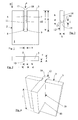
- FIG. 1 shows in a plan view of a flat side 1, a plate 2 with a introduced from a narrow side 3 forth slot 4.
- the slot 4 ends with a slot bottom 5, perpendicular to the parallel and perpendicular to the flat side 1 of the plate 2 introduced slot walls 6.7 stands.
- the width a of the slot 4 and the width c of the slot bottom 5, preferably together with the recesses 8,9, is smaller than the material thickness of this second plate 12th
- a groove 10 is introduced over the slot 4, whose width d is dimensioned larger than the material thickness of the second plate 12th
- the depth e of the groove 10 is dimensioned such that here a circumferential around the slot 4 web 11 remains, which has a defined material thickness f.
- the length g of the groove 10 is dimensioned larger than the length c of the slot 4, so that in the groove 10, even with dimensional tolerances, a system of a second plate 12 can be made over the cross section.
- the second plate 12 is provided with opposing grooves 13,14.
- Their width h, i is in each case dimensioned such that they correspond to the defined material thickness f of the web 11, that is to say that this web 11 is accurately fitted with insertion into the slot 4.
- the material thickness k of the remaining between the grooves 13,14 web 15 is in an exact fit, optionally slightly smaller than the width a of the slot 4, so that a casual introduction of the second plate 12 is ensured in the slot 4.
- the height 1 of the plate 12 corresponds to the length c of the slot 4, so that the upper narrow sides 3, 16 lie in one plane.
- the anticipation of chamfers 17,18 and / or rounding in the narrow side 3 at the ends of the slot walls 6,7, which are useful for the easier insertion of the second plate 12 in the slot 4, is not opposed.
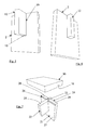
- FIGS. 5 and 6 show different views of the two penetrating plates 2,12. While FIG. 5 shows that the groove 10 remains visible over the slot 4, optionally also in the region of the joint 19 of the two plates 2,12, so shows FIG. 6 a show side, where clean connections between the two plates 2,12 were achieved.
- a first plate 21 and a second plate 22 have been connected to each other according to the foregoing embodiment. Only the height m of the second plate 22 is dimensioned smaller than the length n of the slot 23, so that from the first plate 21, a projection 24 is formed over the upper narrow side 25 of the second plate 22.
- This projection 24 is provided with a fold 26 which is dimensioned such that it terminates on the one hand in the plane of the narrow side 25 of the second plate 22, whereby a T-shaped bearing surface in front of the flat side 27 of the first plate 21 is formed.
- the material thickness of the projection 24 is removed by the fold 26 in such a way that two pins 28, 29 of defined material thickness o remain.
- the length q of the grooves 31,32 as well as the depth of the grooves 31,32 is dimensioned slightly larger than the length and the height r of the pins 28,29, to which the grooves 31,32 possibly also with recesses 34,35 in the manner of Slot 4 can be provided.
- the length s of the remaining between the grooves 31,32 spacer 36 is dimensioned slightly smaller in the direction of the grooves 31,32 as the width of the slot 23 and fits easily into this one.
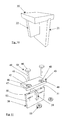
- FIG. 11 shows in the manner of an exploded view, the composite of a first plate 38 with a second plate 39. On this composite of the two plates 38,39 a third plate 40, as explained above, placed.
- the third plate 40 has two round recesses 42,43, each of which serves to receive a head 44 of a thumbscrew 45, wherein a base 46 of these recesses 42,43 a support for the head 44 of Knurled screw 45 is formed.
- a bore 47,48 for a threaded shaft 49 of the thumbscrew 45 is introduced, which are aligned with a respective bore 50 in the narrow side 51 of the first plate 38.
- These bores 50 each intersect a groove 52 which is dimensioned such that a knurled nut 53 can be introduced there for fixing the knurled screw 45.
- the depth of the groove 52 is to be dimensioned and the groove 52 will prevail mostly the plate 38.
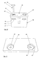
- a groove 55 for receiving a knurled nut 56 towards a narrow side 57 of a plate 58 may be open, cf. FIG. 12 , left half of the picture.
- the support for a head 59 of a thumbscrew 60 can be designed in various ways.
- the left half of the picture FIG. 12 As a result, the support 61 protrudes toward the base 62 of the recess and a gap 63 is formed between the underside of the screw head 59 and the base 62. This can serve, for example, the hanging of loops of seat cushions or the like.
- the support 61 can be formed separately by the plate 54 itself or alternatively by, for example, another knurled nut.
- annular groove 64 still provided, which is connected to a through hole 65, compare FIG. 13 ,
- the depth of the annular groove 65 is dimensioned such that a support 66 protrudes a groove base 67, in which the through-bore 68 is introduced.
- the through-holes 65, 68 are further to be positioned so that they exit next to the first plate 58.
- FIG. 14 shows a furniture set consisting of two benches 69.70 and a table 71st
- the bench 69 has two first plates 73, 74, each provided with feet 75. With outward facing sides according to FIG. 6 the two first plates 73, 74 are connected to one another by a common second plate 76. The two first plates 73, 74 and the common second plate 76 carry a common third plate 77 in the manner explained above.
- the bench 69 is further provided with a screw 78, which, as explained above, a slot 79 leaves, in which a loop 80, for example, a pad support 81 is suspended, compare FIG. 15 ,
- the fittings 82 are according to FIG. 11 formed so that no screw heads of the flat side 83 of serving as a table top third plate 84 protrude.
Landscapes
- Engineering & Computer Science (AREA)
- General Engineering & Computer Science (AREA)
- Mechanical Engineering (AREA)
- Life Sciences & Earth Sciences (AREA)
- Wood Science & Technology (AREA)
- Furniture Connections (AREA)
- Connection Of Plates (AREA)
Applications Claiming Priority (1)
| Application Number | Priority Date | Filing Date | Title |
|---|---|---|---|
| DE200910020724 DE102009020724A1 (de) | 2009-05-11 | 2009-05-11 | Plattenverbindung und ihre Herstellung |
Publications (1)
| Publication Number | Publication Date |
|---|---|
| EP2250926A2 true EP2250926A2 (fr) | 2010-11-17 |
Family
ID=42557448
Family Applications (1)
| Application Number | Title | Priority Date | Filing Date |
|---|---|---|---|
| EP20100003175 Withdrawn EP2250926A2 (fr) | 2009-05-11 | 2010-03-25 | Assemblage de plaques et leur préparation |
Country Status (2)
| Country | Link |
|---|---|
| EP (1) | EP2250926A2 (fr) |
| DE (2) | DE102009020724A1 (fr) |
Cited By (3)
| Publication number | Priority date | Publication date | Assignee | Title |
|---|---|---|---|---|
| US9175703B2 (en) | 2008-12-17 | 2015-11-03 | Unilin, Bvba | Composed element, multi-layered board and panel-shaped element for forming this composed element |
| US9719542B2 (en) | 2010-06-03 | 2017-08-01 | Unilin, Bvba | Composed element and corner connection applied herewith |
| US10293512B2 (en) | 2011-06-29 | 2019-05-21 | Unilin Bvba | Drawer, drawer construction and method for manufacturing a drawer |
Families Citing this family (1)
| Publication number | Priority date | Publication date | Assignee | Title |
|---|---|---|---|---|
| DE102022108044A1 (de) | 2022-04-04 | 2023-10-05 | Scolotech Gmbh | Verbindungsvorrichtung, Einlegeteil für die Verbindungsvorrichtung und Verfahren zu einem Verbinden von Platten mittels der Verbindungsvorrichtung |
Citations (1)
| Publication number | Priority date | Publication date | Assignee | Title |
|---|---|---|---|---|
| DE19705107A1 (de) | 1997-02-12 | 1998-08-13 | Moewa Warenhandel Gmbh | Regal, Behälter oder dergleichen |
-
2009
- 2009-05-11 DE DE200910020724 patent/DE102009020724A1/de not_active Withdrawn
-
2010
- 2010-03-25 DE DE202010017751U patent/DE202010017751U1/de not_active Expired - Lifetime
- 2010-03-25 EP EP20100003175 patent/EP2250926A2/fr not_active Withdrawn
Patent Citations (1)
| Publication number | Priority date | Publication date | Assignee | Title |
|---|---|---|---|---|
| DE19705107A1 (de) | 1997-02-12 | 1998-08-13 | Moewa Warenhandel Gmbh | Regal, Behälter oder dergleichen |
Cited By (16)
| Publication number | Priority date | Publication date | Assignee | Title |
|---|---|---|---|---|
| US10935063B2 (en) | 2008-12-17 | 2021-03-02 | Unilin Bv | Composed element, multi-layered board and panel-shaped element for forming this composed element |
| US11085475B2 (en) | 2008-12-17 | 2021-08-10 | Flooring Industries Limited, Sarl | Composed element, multi-layered board and panel-shaped element for forming this composed element |
| US9695856B2 (en) | 2008-12-17 | 2017-07-04 | Unilin, Bvba | Composed element, multi-layered board and panel-shaped element for forming this composed element |
| US12123441B2 (en) | 2008-12-17 | 2024-10-22 | Unilin Bv | Composed element, multi-layered board and panel-shaped element for forming this composed element |
| US9797427B2 (en) | 2008-12-17 | 2017-10-24 | Unilin, Bvba | Composed element, multi-layered board and panel-shaped element for forming this composed element |
| US11788568B2 (en) | 2008-12-17 | 2023-10-17 | Flooring Industries Limited Sarl | Composed element, multi-layered board and panel-shaped element for forming this composed element |
| US9347470B2 (en) | 2008-12-17 | 2016-05-24 | Unilin, Bvba | Composed element, multi-layered board and panel-shaped element for forming this composed element |
| US11319977B2 (en) | 2008-12-17 | 2022-05-03 | Flooring Industries Limited, Sarl | Composed element, multi-layered board and panel-shaped element for forming this composed element |
| US9175703B2 (en) | 2008-12-17 | 2015-11-03 | Unilin, Bvba | Composed element, multi-layered board and panel-shaped element for forming this composed element |
| US10731689B2 (en) | 2008-12-17 | 2020-08-04 | Unilin, Bvba | Composed element, multi-layered board and panel-shaped element for forming this composed element |
| US10323670B2 (en) | 2008-12-17 | 2019-06-18 | Unilin, Bvba | Composed element, multi-layered board and panel-shaped element for forming this composed element |
| US10982700B2 (en) | 2010-06-03 | 2021-04-20 | Unilin Bv | Composed element and corner connection applied herewith |
| US12000418B2 (en) | 2010-06-03 | 2024-06-04 | Unilin, Bv | Composed element and corner connection applied herewith |
| US9719542B2 (en) | 2010-06-03 | 2017-08-01 | Unilin, Bvba | Composed element and corner connection applied herewith |
| US12607216B2 (en) | 2010-06-03 | 2026-04-21 | Unilin, Bv | Composed element and corner connection applied herewith |
| US10293512B2 (en) | 2011-06-29 | 2019-05-21 | Unilin Bvba | Drawer, drawer construction and method for manufacturing a drawer |
Also Published As
| Publication number | Publication date |
|---|---|
| DE202010017751U1 (de) | 2012-07-30 |
| DE102009020724A1 (de) | 2010-11-25 |
Similar Documents
| Publication | Publication Date | Title |
|---|---|---|
| EP1350904B2 (fr) | Planches de plancher | |
| EP2250926A2 (fr) | Assemblage de plaques et leur préparation | |
| EP2640983B1 (fr) | Dispositif de liaison | |
| AT394252B (de) | Gehrungsverbindung | |
| DE102018112950B4 (de) | Schraubenlos montierbares Möbelsystem und ein schraubenloses Verbindungssystem sowie ein Verfahren zu dessen Herstellung und Montage | |
| EP0038086A2 (fr) | Elément de construction pour la production de tréteaux, meubles, étagères, bâtiments transportables et objet construit à partir de cet élément | |
| EP0970284B1 (fr) | Cadre destine a etre utilise comme element de construction modulaire pour des batiments et procede de fabrication d'un tel cadre | |
| DE4327754C2 (de) | Möbel, wie Bücherborde oder Tische und Regalsysteme | |
| DE2506616A1 (de) | Aus einzelelementen zusammensetzbare und zerlegbare struktur, insbesondere zur gestaltung von einrichtungsgegenstaenden | |
| EP4221936B1 (fr) | Plaque avec au moins une fente dans sa surface et écrou à fente | |
| DE3320962C2 (de) | Eckverbindung | |
| DE3210915A1 (de) | Baustein und aus diesem gebildete wand | |
| DE3835191C2 (fr) | ||
| DE1136813B (de) | Formschluessige Verbindung von miteinander zu verleimenden Holzteilen | |
| WO1988004531A1 (fr) | Procede pour fabriquer des panneaux d'epaisseur differente en bois ou en materiaux de substitution du bois | |
| AT390105B (de) | Parkettfussbodenelement | |
| DE102004016890A1 (de) | Gratverbinder und Möbel oder Bauwerk | |
| DE4337859A1 (de) | Modulbauelemente für Konstruktionen zum Tragen und Halten von Werkstücken | |
| EP1605172B1 (fr) | Ferrure pour assembler un élément structural allongé et un élément structural plat | |
| DE202023106301U1 (de) | Verbinder zum Verbinden von Stangenmaterial | |
| DE102024121007A1 (de) | System mit einzelnen Platten zum Aufbau eines Möbelstücks | |
| DE102023003082A1 (de) | Die vorliegende Erfindung betrifft ein Regalsystem, umfassend Knotenelemente, Verbindungselemente und zumindest einen Regalboden. | |
| DE2410211A1 (de) | Kombinationsmoebel | |
| DE202024106954U1 (de) | Gelenkelement für ein auf- und abbaubares Bett | |
| DE102022131160A1 (de) | Einbauelement zur Aufbewahrung von Gegenständen in einer Trockenbauwand und Anordnung hiermit |
Legal Events
| Date | Code | Title | Description |
|---|---|---|---|
| PUAI | Public reference made under article 153(3) epc to a published international application that has entered the european phase |
Free format text: ORIGINAL CODE: 0009012 |
|
| AK | Designated contracting states |
Kind code of ref document: A2 Designated state(s): AT BE BG CH CY CZ DE DK EE ES FI FR GB GR HR HU IE IS IT LI LT LU LV MC MK MT NL NO PL PT RO SE SI SK SM TR |
|
| AX | Request for extension of the european patent |
Extension state: AL BA ME RS |
|
| STAA | Information on the status of an ep patent application or granted ep patent |
Free format text: STATUS: THE APPLICATION IS DEEMED TO BE WITHDRAWN |
|
| 18D | Application deemed to be withdrawn |
Effective date: 20121002 |