EP2250936A2 - Führung mit "push-pull" Vorrichtung für Möbel - Google Patents
Führung mit "push-pull" Vorrichtung für Möbel Download PDFInfo
- Publication number
- EP2250936A2 EP2250936A2 EP10161246A EP10161246A EP2250936A2 EP 2250936 A2 EP2250936 A2 EP 2250936A2 EP 10161246 A EP10161246 A EP 10161246A EP 10161246 A EP10161246 A EP 10161246A EP 2250936 A2 EP2250936 A2 EP 2250936A2
- Authority
- EP
- European Patent Office
- Prior art keywords
- push
- slider
- parts
- guide
- tooth
- Prior art date
- Legal status (The legal status is an assumption and is not a legal conclusion. Google has not performed a legal analysis and makes no representation as to the accuracy of the status listed.)
- Withdrawn
Links
Images
Classifications
-
- A—HUMAN NECESSITIES
- A47—FURNITURE; DOMESTIC ARTICLES OR APPLIANCES; COFFEE MILLS; SPICE MILLS; SUCTION CLEANERS IN GENERAL
- A47B—TABLES; DESKS; OFFICE FURNITURE; CABINETS; DRAWERS; GENERAL DETAILS OF FURNITURE
- A47B88/00—Drawers for tables, cabinets or like furniture; Guides for drawers
- A47B88/40—Sliding drawers; Slides or guides therefor
- A47B88/453—Actuated drawers
- A47B88/46—Actuated drawers operated by mechanically-stored energy, e.g. by springs
- A47B88/463—Actuated drawers operated by mechanically-stored energy, e.g. by springs self-opening
Definitions
- the present finding refers to a linear guide for furniture provided with a push-pull opening system.
- the guide/s are positioned longitudinally inside the compartment, they support a second container and they free the space of the compartment at the front part with respect to the operator, common examples being drawers (where the guides occupy the sides of the compartment) or the basket systems (where the guides occupy the upper part and the lower part of the compartment).
- the second category instead provides for an arrangement of the guide/s occupying - with the longitudinal side thereof - the front surface of the compartment in such a manner that access occurs by sliding the shutter vertically or horizontally with respect to the user.
- sliding in case of horizontal translation, or “shutter” in case the sliding occurs vertically.
- the retention of the drawer or shutter at the closed position may occur, according to the prior art, through suitable mechanical engagements or magnetic force.
- the mechanical engagements usually have moveable parts subjected to wear and jamming and which may have problems related to overall dimensions, while the retention by magnetic force reveals problems regarding dimensioning, especially in the sliding systems such as drawers, where the weight of the object to be retained varies considerably depending on the use.
- a general object of the present invention is that of overcoming the drawbacks mentioned above by providing a linear guide having a simple and efficient push-pull device.
- a linear guide for furniture comprising two guide parts which mutually slide between a contracted position and an extended position characterised in that it comprises a push-pull device that is integrally joined with one of the two parts and which comprises a slider which, when the push-pull device is actuated, slides pushed by a spring thereof from a receded position ad to an advanced position and in the travel it pushes a push member that is integrally joined with the other of the two guide parts, in such a manner to move said other of the two parts over a first section towards the extended position, the slider being provided with two staggered lateral teeth along the movement axis of the slider and which are dimensioned and oriented the first for pushing onto the push member towards the extended condition of the two parts and the second for retaining - on the slider - the push member when the two guide parts are close to the retracted position and the push-pull device is in the condition having the slider receded.
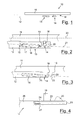
- figure 1 schematically shows a linear guide for furniture, indicated in its entirety with 10.
- the guide 10 comprises two guide parts 11 and 12 which mutually slide between a retracted position and an extended position, according to a substantially known art.
- the sliding mechanism shall thus not be described or shown, given that it may be of any known type.
- part 12 is intended to be fixed onto the furniture and part 11 is intended to be fixed onto the sliding member, for example a drawer.
- Two guides may be used at the sides of the drawer. Even only one of them may be made according to the present invention.
- the guide 10 comprises a push-pull device 13 which is integrally joined to one of the two parts.
- the push-pull device operates interiorly in a substantially known manner and thus the interior thereof shall not be described in detail. Substantially, it comprises a slider 14 which slides between a receded position (shown in figure 2 ) and an extracted or advanced position (shown in figure 3 ).
- a spring 15 inside the body 16 of the push-pull device pushes the slider towards the extracted position.
- a known engagement device 17 engages and allows maintaining the slider in the receded position when the slider is pushed backwards starting from the extracted position. As known, disengaging the device 17 solely requires pushing the slider inwards further.
- the slider 14 in the forward travel thereof pushes a push member 18 which is integrally joined to the other of the two guide parts.
- the slider is provided with two lateral teeth 19, 20 which are staggered along the movement axis 21 of the slider.
- the first of the two teeth (called the push tooth 19) is dimensioned and directed to push against the push member 18 towards the extended condition of the two parts and the second (called the retention tooth 20) is dimensioned and oriented to retain - on the slider - the push member when the two guide parts are close to the retracted position and the push-pull device is in the condition having the slider receded (as shown in figure 2 ).
- the tooth 20 is sufficiently displaced sideways with respect to the member 18 so as to allow surmounting the member 18, in such a manner that the guide may freely continue the extension travel (for opening the drawer) by drawing manually.
- the push member 18 Upon imparting the reverse contraction movement (for closing the drawer) the push member 18 surmounts the tooth 20 again (as shown in figure 3 ) and pushes the tooth 19 backwards in such a manner to reload the push-pull device.
- the system returns to the position of figure 2 and the drawer is once again locked at the closed position.
- An elastic yield due to the movement of the various parts may be used to implement the surmounting of the tooth 20 by the push member 18.
- the guides may also be obtained with the sliding direction 21 of the slider towards an advanced position which is diverging with respect to the sliding direction 22 of the two guide parts towards the extended position, in such a manner that the push member moves away from the coupling with the second tooth when the first tooth pushes against the push member and moves the guides in the first section towards the extended position.
- the axes may also be parallel and the push-pull device (as now easily evincible by a man skilled in the art) may have the slider which, at least in the final part of the push travel thereof, has a side displacement movement from the push member to disengage the second tooth from such push member.
- the push-pull device may be provided, in the moveable part thereof and in the accommodation thereof, a form which causes a side misalignment near the maximum extension position thereof.
- the tooth 20 has a smaller projection from the slider with respect to the projection of the tooth 19.
- the tooth 20 has inclined contact faces with the push member.
- the slider 14 has the part 23 that bears the teeth which comprises a screw 24 for adjusting the position thereof along the push axis.
- Such screw advantageously has the manoeuvre head 25 facing the head of the slider.
- the screw axially passes through the entire part 23 of the slider and is screwed in the remaining rear part 26 of the slider.
- the head of the screw is rotatable but axially locked against the part 23 while a projection 27 prevents the rotation of part 23 with respect to part 26.
- the stop position shown in figure 2 may thus be adjusted. This for example allows adjusting the closure aligning of the front part of the drawer.
- the shape of the sliding guides may vary with respect to that shown in the figure, even depending on the sliding member to be moved.
- the guides may also be formed in three or more mutually sliding pieces, as easily imaginable by a man skilled in the art.
- guides with sliding parts should be considered broader than a simple guide for drawers and it may comprise other members for the sliding movement of furniture parts.
Landscapes
- Engineering & Computer Science (AREA)
- Mechanical Engineering (AREA)
- Drawers Of Furniture (AREA)
- Push-Button Switches (AREA)
- Catching Or Destruction (AREA)
Applications Claiming Priority (1)
| Application Number | Priority Date | Filing Date | Title |
|---|---|---|---|
| IT000157U ITMI20090157U1 (it) | 2009-05-13 | 2009-05-13 | Guida con push-pull per mobili |
Publications (1)
| Publication Number | Publication Date |
|---|---|
| EP2250936A2 true EP2250936A2 (de) | 2010-11-17 |
Family
ID=42655617
Family Applications (1)
| Application Number | Title | Priority Date | Filing Date |
|---|---|---|---|
| EP10161246A Withdrawn EP2250936A2 (de) | 2009-05-13 | 2010-04-28 | Führung mit "push-pull" Vorrichtung für Möbel |
Country Status (2)
| Country | Link |
|---|---|
| EP (1) | EP2250936A2 (de) |
| IT (1) | ITMI20090157U1 (de) |
Cited By (1)
| Publication number | Priority date | Publication date | Assignee | Title |
|---|---|---|---|---|
| US10517396B2 (en) | 2018-02-27 | 2019-12-31 | King Slide Works Co., Ltd. | Slide rail assembly |
-
2009
- 2009-05-13 IT IT000157U patent/ITMI20090157U1/it unknown
-
2010
- 2010-04-28 EP EP10161246A patent/EP2250936A2/de not_active Withdrawn
Non-Patent Citations (1)
| Title |
|---|
| None |
Cited By (1)
| Publication number | Priority date | Publication date | Assignee | Title |
|---|---|---|---|---|
| US10517396B2 (en) | 2018-02-27 | 2019-12-31 | King Slide Works Co., Ltd. | Slide rail assembly |
Also Published As
| Publication number | Publication date |
|---|---|
| ITMI20090157U1 (it) | 2010-11-14 |
Similar Documents
| Publication | Publication Date | Title |
|---|---|---|
| EP2262397B1 (de) | Vorrichtung zur öffnung und schliessung eines beweglichen teils eines möbelstücks | |
| JP5390190B2 (ja) | 第1および第2家具部分を有する家具アイテム | |
| KR102012573B1 (ko) | 가구 구동 장치 | |
| TWI437967B (zh) | 特別用於活動傢俱件之自行關閉裝置 | |
| US20180087305A1 (en) | Ejection device for a movable furniture part | |
| US8079653B2 (en) | Sliding track assembly | |
| US9775434B2 (en) | Drive device for moveable furniture component | |
| JP2012511643A5 (de) | ||
| EP3298927A1 (de) | Gleitvorrichtung | |
| US20160150880A1 (en) | Self-closing slide rail assembly with deceleration mechanism | |
| US10058175B2 (en) | Drive device for a movable furniture part | |
| CN104427908A (zh) | 用于活动家具部件的驱动装置 | |
| JP2014512467A (ja) | 家具の変位部分のための自動開閉装置及び関連装置の集合体 | |
| KR20170142168A (ko) | 이동식 가구 부품용 이젝션 장치 | |
| AT513856A5 (de) | Selbsteinzugsvorrichtung für ein verschiebbares Möbelteil | |
| EP3034722A1 (de) | Schrankschubladenpositionshaltemechanismus | |
| EP2250936A2 (de) | Führung mit "push-pull" Vorrichtung für Möbel | |
| CN103653891B (zh) | 滑轨总成及自我启闭式的滑轨总成 | |
| MY210335A (en) | Drive device for a moveable furniture part | |
| CN109922694B (zh) | 家具和用于打开抽屉和内抽屉的方法 | |
| SI25743A (sl) | Izvlečni predal pri gospodinjskem aparatu | |
| HK1157593B (en) | Device for opening and closing a movable part of a furniture unit | |
| KR200490501Y1 (ko) | 선셰이드 조립체 | |
| US20140236204A1 (en) | Surgical instrument | |
| HK1158721B (en) | Self-closing and opening device particularly for a movable furniture part |
Legal Events
| Date | Code | Title | Description |
|---|---|---|---|
| PUAI | Public reference made under article 153(3) epc to a published international application that has entered the european phase |
Free format text: ORIGINAL CODE: 0009012 |
|
| AK | Designated contracting states |
Kind code of ref document: A2 Designated state(s): AT BE BG CH CY CZ DE DK EE ES FI FR GB GR HR HU IE IS IT LI LT LU LV MC MK MT NL NO PL PT RO SE SI SK SM TR |
|
| AX | Request for extension of the european patent |
Extension state: AL BA ME RS |
|
| STAA | Information on the status of an ep patent application or granted ep patent |
Free format text: STATUS: THE APPLICATION IS DEEMED TO BE WITHDRAWN |
|
| 18D | Application deemed to be withdrawn |
Effective date: 20121101 |