EP2251507A1 - Poteau avec un élément de la fixation pour un grillage - Google Patents
Poteau avec un élément de la fixation pour un grillage Download PDFInfo
- Publication number
- EP2251507A1 EP2251507A1 EP09468003A EP09468003A EP2251507A1 EP 2251507 A1 EP2251507 A1 EP 2251507A1 EP 09468003 A EP09468003 A EP 09468003A EP 09468003 A EP09468003 A EP 09468003A EP 2251507 A1 EP2251507 A1 EP 2251507A1
- Authority
- EP
- European Patent Office
- Prior art keywords
- fastening element
- pole
- leg
- wire fence
- transversal
- Prior art date
- Legal status (The legal status is an assumption and is not a legal conclusion. Google has not performed a legal analysis and makes no representation as to the accuracy of the status listed.)
- Withdrawn
Links
- 230000000295 complement effect Effects 0.000 claims description 5
- 239000002184 metal Substances 0.000 description 2
- 230000002349 favourable effect Effects 0.000 description 1
- 238000009434 installation Methods 0.000 description 1
- 239000000463 material Substances 0.000 description 1
- 238000000034 method Methods 0.000 description 1
- 229920003023 plastic Polymers 0.000 description 1
- 239000004033 plastic Substances 0.000 description 1
Images

Classifications
-
- E—FIXED CONSTRUCTIONS
- E04—BUILDING
- E04H—BUILDINGS OR LIKE STRUCTURES FOR PARTICULAR PURPOSES; SWIMMING OR SPLASH BATHS OR POOLS; MASTS; FENCING; TENTS OR CANOPIES, IN GENERAL
- E04H17/00—Fencing, e.g. fences, enclosures, corrals
- E04H17/02—Wire fencing, e.g. made of wire mesh
- E04H17/10—Wire fencing, e.g. made of wire mesh characterised by the way of connecting wire to posts; Droppers
- E04H17/124—Wire fencing, e.g. made of wire mesh characterised by the way of connecting wire to posts; Droppers connecting by one or more clamps, clips, screws, wedges or ties
Definitions
- the subject of the present invention is a pole with a fastening element for a wire fence.
- a technical problem solved by the present invention is how to design such pole with a fastening element for a wire fence that would allow for a quick and simple arrangement of a wire fence, wherein the fastening element would compensate for relatively large expected tolerances in setting up poles with respect to the size of an individual wire fence element and for fastening by means of a special tool and a fixing element adapted to said tool with the aim that a lack of such tool would render it impossible to install and even more importantly disassemble individual wire fence elements without causing considerable and permanent damage on poles, fastening elements and fence elements.
- Wire fences of the type with poles being of a simple, multiside, preferably rectangular shape, with wire fence elements consisting of upright, wire elements curved at several spots and of transversal wire sections running along vertical sections are known. Edge upright sections of fence elements are intended for a removable fastening on poles. If need may be, intermediate poles are also provided. All said connections share a common characteristic: they are of a screw type that need special large metal washers that partly embrace fence wires. Screws are conventional.
- a further need is a quicker and simpler installation in order to meet a more favourable price on the market.
- a pole with a fastening element for wire fences of the invention the characteristic of which lies in that it comprises grooves with positioning projections and an optional number of fastening elements in said grooves, said fastening elements being positioned at selected spots defined by positioning projections, wherein fastening elements comprise relatively large spaces for edge wire fence sections that allow for dimension deviations in setting up poles, and most importantly, said fastening elements comprise spaces for latching inserts that snap fit into fastening elements in selected locations including edge wire fence sections, wherein said latching inserts are insertable and removable only by a special tool.
- Each disassembly without use of a special tool causes damage on the elements of the assembly of the invention, often irreparable damage.
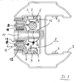
- a pole 1 has an optional cross section having at least one longitudinal groove 2, on at least one lateral side of which there are equidistantly arranged projections 3.
- the number of longitudinal grooves 2 and their mutual angular arrangement within said pole 1 depends on the number of wire fences a pole should connect and on their mutual ground floor angular arrangement.
- Said projections 3 are preferably hemispheric.
- Each groove 2 comprises at least one fastening element 4 of a wire fence 5 that is not subject of the present invention.
- Said fastening element 4 is formed as a profile having an approximate cross-section in the shape of the letter E.
- Transversal legs 6 of said element 4 intended to lean on lateral surfaces of said groove 2 are formed as bearings 7 complementarily arranged with projections 3 on lateral surfaces of said grooves 2 on said pole 1. In this way each fastening element 4 is positionable on an optional place within said groove 2 with respect to complementar co-operation of projections 3 and bearings 7.
- Connecting legs 8 of each fastening element 4 each connect one transversal leg 6 and the central transversal leg 9.
- At least one connecting leg 8 is formed as a meander and with an elastic wall. The elasticity of the wall allows for the approximation of both transversal legs 6 in so much that said fastening element 4 is insertable into said groove 2 anywhere with respect to the positions of said projections 3 that are supposed to be in said bearings 7, when said fastening element 4 is properly positioned.
- Each connecting leg 8 is preferably formed as a U-profile connected with said transversal leg 6 and said central transversal leg 9 with its free ends.
- a latching insert 11 shaped like a comb that fills in said slots 10 with its free legs 12, with which said fastening element 4 is fixed in said groove 2.
- Said free leg 12 of said latch insert 11 comprises at least one snap fitting 13 engaging with said complementary element 14 on said fastening element 4 in a way that said snap fitting 13 cannot be removed in mutual snap position without use of a special tool and without damaging said fastening element 4 and said snap fitting 13, wherein an act of vandalism would take much time and skill.
- Said free leg 12 lies opposite said snap fitting 13 and has a chamfering 15 so that a special tool may be used to elastically bend said free leg 12 in the area of said chamfering 15 so that said snap fitting 13 deflects from said complementary element 14, which makes it possible to remove said latching insert 11 from said slot 10. It goes without saying that said chamfering 15 is also/or made on the neighbouring connecting leg 8. The mentioned special tool is not subject of the present invention.
- Said snap fitting 13 and said complementary element 14 are preferably conceived as a tooth and a tooth bearing, wherein they are located both in said fastening element 4 and in said latching insert 11, which makes them very difficult to reach with any inadequate means to release their connection.
- a special tool is intended to position and remove said snap fitting 12 from said fastening element 4, said tool being only available for authorised persons.
- each transversal leg 6 and transversal leg 9 of said fastening element 4 there are elastic springs 16 to embrace said wire fence 5, resulting in no backlash between the grip of said fence 5 in said fastening element 4 despite expected relatively large possible tolerances of the diameter of a pole of said wire fence 5, extensions due to changes in temperature and assembling tolerances.
- Said transversal leg 9 may have at least one central hole 17 for a possible screw connection of said element 4 directly to an optional background, e.g. to a wall and due to a smaller consumption of material.
- Said pole 1 is preferably made of sheet metal into a hollow profile, wherein said fastening element 4 and said latching insert 11 are made of plastics by known technological methods.
Landscapes
- Engineering & Computer Science (AREA)
- Architecture (AREA)
- Civil Engineering (AREA)
- Structural Engineering (AREA)
- Fencing (AREA)
Priority Applications (1)
| Application Number | Priority Date | Filing Date | Title |
|---|---|---|---|
| EP09468003A EP2251507A1 (fr) | 2009-05-11 | 2009-05-11 | Poteau avec un élément de la fixation pour un grillage |
Applications Claiming Priority (1)
| Application Number | Priority Date | Filing Date | Title |
|---|---|---|---|
| EP09468003A EP2251507A1 (fr) | 2009-05-11 | 2009-05-11 | Poteau avec un élément de la fixation pour un grillage |
Publications (1)
| Publication Number | Publication Date |
|---|---|
| EP2251507A1 true EP2251507A1 (fr) | 2010-11-17 |
Family
ID=41066511
Family Applications (1)
| Application Number | Title | Priority Date | Filing Date |
|---|---|---|---|
| EP09468003A Withdrawn EP2251507A1 (fr) | 2009-05-11 | 2009-05-11 | Poteau avec un élément de la fixation pour un grillage |
Country Status (1)
| Country | Link |
|---|---|
| EP (1) | EP2251507A1 (fr) |
Cited By (3)
| Publication number | Priority date | Publication date | Assignee | Title |
|---|---|---|---|---|
| FR3077321A1 (fr) * | 2018-02-01 | 2019-08-02 | Dirickx Groupe | Piece de fixation d'au moins un panneau de grillage a un poteau de cloture, poteau de cloture et outil de pose correspondants |
| EP3521536A1 (fr) * | 2018-02-01 | 2019-08-07 | Picot | Pièce de fixation d'au moins un panneau de grillage à un poteau de clôture, poteau de clôture et outil de pose correspondants |
| EP3848538A1 (fr) * | 2020-01-09 | 2021-07-14 | Björn Marc E. Van Houtven | Pince pour fixer un panneau de grillage dans une clôture comportant des piquets de clôture et clôture ainsi équipée |
Citations (4)
| Publication number | Priority date | Publication date | Assignee | Title |
|---|---|---|---|---|
| EP0443441A1 (fr) * | 1990-02-17 | 1991-08-28 | Adronit Verwaltungs GmbH. & Co. GbR mbH. | Grillage |
| GB2276401A (en) * | 1993-03-26 | 1994-09-28 | S M Cerramiento | Securing a fencing panel to a fence post |
| GB2322881A (en) * | 1997-02-19 | 1998-09-09 | Sgb Services Plc | Adjustable panelling |
| GB2414034A (en) * | 2004-02-27 | 2005-11-16 | John Fell | Locking device for temporary fence panels |
-
2009
- 2009-05-11 EP EP09468003A patent/EP2251507A1/fr not_active Withdrawn
Patent Citations (4)
| Publication number | Priority date | Publication date | Assignee | Title |
|---|---|---|---|---|
| EP0443441A1 (fr) * | 1990-02-17 | 1991-08-28 | Adronit Verwaltungs GmbH. & Co. GbR mbH. | Grillage |
| GB2276401A (en) * | 1993-03-26 | 1994-09-28 | S M Cerramiento | Securing a fencing panel to a fence post |
| GB2322881A (en) * | 1997-02-19 | 1998-09-09 | Sgb Services Plc | Adjustable panelling |
| GB2414034A (en) * | 2004-02-27 | 2005-11-16 | John Fell | Locking device for temporary fence panels |
Cited By (4)
| Publication number | Priority date | Publication date | Assignee | Title |
|---|---|---|---|---|
| FR3077321A1 (fr) * | 2018-02-01 | 2019-08-02 | Dirickx Groupe | Piece de fixation d'au moins un panneau de grillage a un poteau de cloture, poteau de cloture et outil de pose correspondants |
| EP3521536A1 (fr) * | 2018-02-01 | 2019-08-07 | Picot | Pièce de fixation d'au moins un panneau de grillage à un poteau de clôture, poteau de clôture et outil de pose correspondants |
| EP3848538A1 (fr) * | 2020-01-09 | 2021-07-14 | Björn Marc E. Van Houtven | Pince pour fixer un panneau de grillage dans une clôture comportant des piquets de clôture et clôture ainsi équipée |
| BE1027973B1 (nl) * | 2020-01-09 | 2021-08-10 | Van Houtven Bjoern Marc E | Clips voor het bevestigen van een draadpaneel in een hek met steunpalen en hek daarmee uitgerust |
Similar Documents
| Publication | Publication Date | Title |
|---|---|---|
| US7934699B2 (en) | Fence system | |
| US9027897B2 (en) | Standoff connector for use, for example, as a post base | |
| US7279637B1 (en) | Stainless steel faceplates with labels | |
| US9695612B2 (en) | Aluminum fence design | |
| US6415564B1 (en) | Arrangement for fastening a grille in a frame section | |
| US20120174516A1 (en) | Locking Panel Veneer System | |
| US20030127575A1 (en) | Fence rail cap bracket assembly | |
| US10533340B1 (en) | Rackable fence panel | |
| US20120235105A1 (en) | Quick clip for fence posts | |
| US20230123821A1 (en) | Fence | |
| US5803438A (en) | Plastic fencing | |
| EP2177841B1 (fr) | Grille d'aération pour la protection des appareils | |
| ES2285950B1 (es) | Sistema de fijacion para tarima de madera para exterior. | |
| AU2016101046A4 (en) | A temporary fencing system | |
| US8117775B2 (en) | Sign attachment device | |
| WO2018081865A1 (fr) | Système de protection | |
| US6804891B1 (en) | Door and drawer pull jig | |
| US20210087847A1 (en) | Gate corner insert | |
| EP2149952A1 (fr) | Support pour pluriel mécanismes électrique | |
| KR100806924B1 (ko) | 타공형 인테리어 패널의 브라켓 조립 구조 | |
| GB2465084A (en) | Fence kit and method of erecting a fence | |
| DE202005011883U1 (de) | Aufhängeeinheit für Gegenstände | |
| AU2009202716B2 (en) | Sign Attachment Device | |
| WO2005108718A1 (fr) | Espaceur de fils metalliques pour cloture | |
| KR200332735Y1 (ko) | 조류 접근 방지 장치 |
Legal Events
| Date | Code | Title | Description |
|---|---|---|---|
| PUAI | Public reference made under article 153(3) epc to a published international application that has entered the european phase |
Free format text: ORIGINAL CODE: 0009012 |
|
| AK | Designated contracting states |
Kind code of ref document: A1 Designated state(s): AT BE BG CH CY CZ DE DK EE ES FI FR GB GR HR HU IE IS IT LI LT LU LV MC MK MT NL NO PL PT RO SE SI SK TR |
|
| AX | Request for extension of the european patent |
Extension state: AL BA RS |
|
| 17P | Request for examination filed |
Effective date: 20110516 |
|
| 17Q | First examination report despatched |
Effective date: 20110615 |
|
| GRAP | Despatch of communication of intention to grant a patent |
Free format text: ORIGINAL CODE: EPIDOSNIGR1 |
|
| STAA | Information on the status of an ep patent application or granted ep patent |
Free format text: STATUS: THE APPLICATION IS DEEMED TO BE WITHDRAWN |
|
| 18D | Application deemed to be withdrawn |
Effective date: 20120918 |