EP2251631A1 - Heizvorrichtung und Verfahren zu deren Herstellung - Google Patents
Heizvorrichtung und Verfahren zu deren Herstellung Download PDFInfo
- Publication number
- EP2251631A1 EP2251631A1 EP09006353A EP09006353A EP2251631A1 EP 2251631 A1 EP2251631 A1 EP 2251631A1 EP 09006353 A EP09006353 A EP 09006353A EP 09006353 A EP09006353 A EP 09006353A EP 2251631 A1 EP2251631 A1 EP 2251631A1
- Authority
- EP
- European Patent Office
- Prior art keywords
- heat
- absorbing liquid
- emitting
- plate
- heating unit
- Prior art date
- Legal status (The legal status is an assumption and is not a legal conclusion. Google has not performed a legal analysis and makes no representation as to the accuracy of the status listed.)
- Withdrawn
Links
Images




Classifications
-
- F—MECHANICAL ENGINEERING; LIGHTING; HEATING; WEAPONS; BLASTING
- F28—HEAT EXCHANGE IN GENERAL
- F28F—DETAILS OF HEAT-EXCHANGE AND HEAT-TRANSFER APPARATUS, OF GENERAL APPLICATION
- F28F9/00—Casings; Header boxes; Auxiliary supports for elements; Auxiliary members within casings
- F28F9/02—Header boxes; End plates
- F28F9/0246—Arrangements for connecting header boxes with flow lines
- F28F9/0251—Massive connectors, e.g. blocks; Plate-like connectors
- F28F9/0253—Massive connectors, e.g. blocks; Plate-like connectors with multiple channels, e.g. with combined inflow and outflow channels
-
- F—MECHANICAL ENGINEERING; LIGHTING; HEATING; WEAPONS; BLASTING
- F28—HEAT EXCHANGE IN GENERAL
- F28D—HEAT-EXCHANGE APPARATUS, NOT PROVIDED FOR IN ANOTHER SUBCLASS, IN WHICH THE HEAT-EXCHANGE MEDIA DO NOT COME INTO DIRECT CONTACT
- F28D9/00—Heat-exchange apparatus having stationary plate-like or laminated conduit assemblies for both heat-exchange media, the media being in contact with different sides of a conduit wall
- F28D9/0031—Heat-exchange apparatus having stationary plate-like or laminated conduit assemblies for both heat-exchange media, the media being in contact with different sides of a conduit wall the conduits for one heat-exchange medium being formed by paired plates touching each other
- F28D9/0043—Heat-exchange apparatus having stationary plate-like or laminated conduit assemblies for both heat-exchange media, the media being in contact with different sides of a conduit wall the conduits for one heat-exchange medium being formed by paired plates touching each other the plates having openings therein for circulation of at least one heat-exchange medium from one conduit to another
- F28D9/005—Heat-exchange apparatus having stationary plate-like or laminated conduit assemblies for both heat-exchange media, the media being in contact with different sides of a conduit wall the conduits for one heat-exchange medium being formed by paired plates touching each other the plates having openings therein for circulation of at least one heat-exchange medium from one conduit to another the plates having openings therein for both heat-exchange media
Definitions
- the present invention relates to a heating unit in accordance with the preamble of claim 1 and a method for manufacturing thereof.
- a heating unit in accordance with the preamble of claim 1 is known from EP 1 500 896 A1 , wherein the whole contents thereof is incorporated into the present specification by reference.
- the heating unit of EP 1 500 896 A1 comprises a gasketed plate heat exchanger with a coupling element containing channels from the liquid supply and discharge lines to the heat exchanger.
- the coupling element comprises a casted block.
- the heating unit of EP 1 500 896 A1 is relatively heavy.
- a heating unit comprising a plate heat exchanger having a plurality of heat exchanger plates combined to form a plate stack defining flow passages of a primary circuit having a heat-emitting liquid inlet and a heat-emitting liquid outlet and flow passages of a secondary circuit having a heat-absorbing liquid inlet and a heat-absorbing liquid outlet, a heat-emitting liquid supply channel for guiding heat-emitting liquid from a heat-emitting liquid supply line to the heat-emitting liquid inlet, a heat-emitting liquid discharge channel for guiding heat-emitting liquid from the heat-emitting liquid outlet to a heat-emitting liquid discharge line, a heat-absorbing liquid supply channel for guiding heat-absorbing liquid from a heat-absorbing liquid supply line for supplying heat-absorbing liquid to the heat-absorbing liquid inlet, and a heat-absorbing liquid discharge channel for guiding heat-absorbing liquid from the heat-absorbing liquid outlet to a heat-absorbing liquid discharge line, wherein the heat-
- the middle plate and the end plate can be steel plates, preferably stainless steel plates.
- the middle plate and the end plate can have a thickness of about 0.5 mm to 5 mm, preferably a thickness of about of 1 mm to 3 mm 1 and can preferably have a thickness of about 2 mm.
- the middle plate can have openings and the end plate can have pressed indents defining the heat-emitting liquid supply channel and the heat-absorbing liquid discharge channel.
- the middle plate and the end plate can have openings and/or pressed indents defining the heat-emitting liquid discharge channel and the heat-absorbing liquid supply channel.
- the heating unit can comprise connection members for connecting the channels to connectors for connecting the channels to the respective supply and discharge lines, wherein preferably the middle plate can comprise pressed indents defining receiving portions for the connection members and/or the end plate can comprise pressed indents defining receiving portions for the connection members.
- heating unit can comprise at least one or a plurality of clinch joints defining the relative position of the middle plate with respect to the end plate.
- heating unit can comprise at least one snap fit or a plurality of snap fits defining the relative position of the middle plate 20) with respect to the end plate, wherein the or each snap fit preferably comprises a snap fit indent provided in middle plate and a snap fit indent (400) provided in the end plate.
- the clinched joints and/or snap fits can be preferably be evenly spaced from each other.
- the clinched joints and/or snap fits can be provided at the edges of the middle plate and the end plate.
- the clinched joints and/or snap fits can be provided in the extension portions of the middle plate and the end plate.
- the or each snap fit can comprise a snap fit indent provided in middle plate and a snap fit indent provided in the end plate.
- the snap fit indent(s) provided in middle plate and the snap fit indent(s) provided in the end plate can have similar shapes fitting together.
- the shapes can be oval, rectangular, circular or irregular shaped. Other shapes are possible.
- the shapes of different snap fits are the same.
- the shapes of different snap fits can also be different from each other. Even the shapes of the indents in the middle plate and end plate of one snap fit can be different as long as a snap fit connection is provided such that an alignment of the middle plate and the end plate in at least one direction is ensured during the joining step.
- the snap fit indent(s) provided in middle plate and the snap fit indent(s) provided in the end plate can comprise respective protrusions and recesses being adapted and dimensioned such that the middle plate and the end plate can be snapped together before they are joined together in a further step, preferably a brazing step, wherein a copper foil is placed between the parts to be brazed together.
- the copper foil can be provided with recesses in the area where the snap fit connection is provided.
- copper foil can be provided also in the area of the snap fit connection.
- the middle plate and the end plate can be brazed together.
- the plate heat exchanger can be a brazed plate heat exchanger or a gasketed plate heat exchanger.
- the middle plate and the end plate can be at least partially be glued or welded together.
- connection methods are possible.
- the connection members can be brazed to the middle plate and the end plate and the plates of the plate heat exchanger can be also brazed together.
- the middle plate can be preferably brazed to the uppermost plate of the plate heat exchanger being adjacent thereto.
- portions of the heat-emitting liquid supply channel and the heat-absorbing liquid discharge channel can be arranged next to each other.
- the heat-emitting liquid supply channel and the heat-absorbing liquid discharge channel can extend from the top portion of the middle plate and the end plate to the bottom portion of the middle plate and the end plate.
- the heat-emitting liquid supply channel and the heat-absorbing liquid discharge channel can be curved.
- This embodiment of the invention has the advantage that the length of the heat-emitting liquid supply channel and the heat-absorbing liquid discharge channel can be greater than for embodiments of the invention where the channels extend directly from the respective inlet/outlet of the plate heat exchanger to the respective connection member. Accordingly a better heat transfer between the liquids in the channels can take place. Preferably the length of these channels can be greater that the length of the middle and end plate.
- the middle plate and the end plate can comprise respective receiving portions for connection members and the middle plate, the connection members and the end plate can be brazed together.
- all parts to be brazed together can be brazed together in one brazing step.
- the end plate and the middle plate can be clinched together by means of at least one and preferably more than one clinched joints before the brazing step takes place in order to ensure the correct alignment of the end plate to the middle plate.
- the middle plate may be clinched to the neighbouring heat exchanger plate (i.e. the last heat exchanger plate closing the heat exchanger at this side) by means of at least one and preferably more than one clinched joints before the brazing step takes place in order to ensure the correct alignment of the middle plate to the heat exchanger plate.
- the heat exchanger plates or at least some of the heat exchanger plates may be clinched together by means of at least one and preferably more than one clinched joints before the brazing step takes place in order to ensure the correct alignment of the stack of heat exchanger plates.
- the brazing step takes place at 1200 °C, wherein all parts are placed into an oven and pressed together, wherein the plates of the heat exchanger preferably comprising indents in the corners of the heat exchanger plates such that the correct alignment during the brazing step is ensured.
- the middle plate and/or the end plate can comprise indents corresponding to at least on corner indent of the heat exchanger plates and preferably with the corner indents of the heat exchanger plates such that an correct alignment of the middle plate to the stack of heat exchanger plates and/or an correct alignment of the end plate to the middle plate is ensured during the brazing step.
- respective copper foils can be placed between all parts to be brazed together before the brazing step.
- the plates of the heat exchanger can be fixed for brazing by means of bending on edge portions of the heat exchanger plates and/or by providing clinched joints.
- clinched joints and/or bendings may be provided at the top at three protrusions of the heat exchanger plates.
- At least one or more, especially two bendings of corners and/or clinched joints in the top of the heat exchanger plates may be provided. This may be sufficient to ensure a correct alignment of the heat exchanger plates in the horizontal direction. In the vertical direction the correct alignment of the heat exchanger plates may be ensured by putting a weight on top of the heat exchanger plates.
- FIG. 1 to 10 Fig. 13 and Fig. 15 there is shown a first embodiment of a heating unit in accordance with the invention.
- Fig. 12 there is shown an alternative end plate 140 of another embodiment of a heating unit in accordance with the invention (see Fig. 16 ) to be combined with a middle plate as shown in Fig. 14 and heat exchanger plates as shown in Fig. 15 .
- the other components of this embodiment correspond to the embodiment as shown in Figs. 1 to 10 . Accordingly essentially only the differences are described and reference is made to the description of the other embodiment.
- the reference numerals referring to the same or similar features are increased by 100 compared to the other embodiment.
- Heating units typically comprises a plate heat exchanger, at least one regulator valve with one or more sensors and couplings for heat-emitting liquid, typically water from central heating plants, couplings for heat-absorbing liquid, typically utility water or liquid medium in a central heating plant.
- the plate heat exchanger comprises a primary circuit and a secondary circuit formed by a plurality of heat exchanger plates being configured in such a manner that separate flow passages are provided between adjoining heat exchanger plates for a heat-emitting liquid in the primary circuit and for a heat-absorbing liquid in the secondary circuit, respectively.
- Plate heat exchangers lend themselves for use in connection with central heating plants and typically within the context of central heating plants for small units such as e.g. one-family houses, villas, flats, where it serves either as plate water heater for heating the utility water, or as plate water heaters for heating a liquid medium used in the central heating system of that unit.
- plate water heaters are used in a context where it is desired to have a central heating installation with a water heater having limited outer dimensions compared to a conventional water heater that often features a receptacle volume of about 100-200 litres of utility water.
- a plate water heater is used for heating utility water
- cold utility water is conveyed into the secondary circuit of the plate heat exchanger.
- hot central heating water is conveyed that emits the heat contained therein by heat transmission to the cold utility water in the secondary circuit, whereby the utility water is heated.
- the heating unit in accordance with the embodiment of the invention as shown in Figs. 1 to 11 comprises a brazed plate heat exchanger 10 comprising a stack of heat exchanger plates 17 (see Fig. 15 ) defining a primary circuit 15 in which in use heat-emitting liquid (or fluid) such as water from central heating plants is flowing and a secondary circuit 16 in which heat-absorbing liquid such as utility water to be used for heating of a room or consumption.
- heat-emitting liquid or fluid
- secondary circuit 16 in which heat-absorbing liquid such as utility water to be used for heating of a room or consumption.
- the plate heat exchanger 10 comprises a heat-emitting liquid inlet 11 which is defined by holes in the individual plates (see Fig. 15 ) which are sealed against the secondary circuit 16 and open to the primary circuit 15 in a manner known to the skilled person.
- the individual plates are brazed together by interposing a copper foil in between the individual plates before brazing at the locations where the brazing shall take place to provide the sealing.
- the plate heat exchanger 10 also comprises a heat-absorbing liquid outlet 12 open to the secondary circuit 16 and closed to the primary circuit 15, a heat-emitting liquid outlet 13 open to the primary circuit 15 and closed to the secondary circuit 16 and a heat-absorbing liquid inlet 14 open to the secondary circuit 16 and closed to the primary circuit 15.
- the heat unit also comprises a middle plate 20 and an end plate 40 defining there between a heat-emitting liquid supply channel 61 for guiding heat-emitting liquid from a heat-emitting liquid supply line to the heat-emitting liquid inlet 11, a heat-emitting liquid discharge channel 63 for guiding heat-emitting liquid from the heat-emitting liquid outlet 13 to a heat-emitting liquid discharge line, a heat-absorbing liquid supply channel 64 for guiding heat-absorbing liquid from a heat-absorbing liquid supply line for supplying heat-absorbing liquid to the heat-absorbing liquid inlet 14, and a heat-absorbing liquid discharge channel 62 for guiding heat-absorbing liquid from the heat-absorbing liquid outlet 12 to a heat-absorbing liquid discharge line.
- a heat-emitting liquid supply channel 61 for guiding heat-emitting liquid from a heat-emitting liquid supply line to the heat-emitting liquid inlet 11
- a heat-emitting liquid discharge channel 63 for guiding heat-emitting liquid from the heat-
- the middle plate 20 comprises a flat heat exchanger portion 30 corresponding to the extensions of the heat exchanger plates.
- the middle plate is brazed to the last heat exchanger plate closing the heat exchanger at this side.
- a similar closing plate is provided in a manner known to the skilled person.
- the end plate 40 comprises a heat exchanger portion 50 into which indents are pressed defining the heat-emitting liquid supply channel 61, the heat-emitting liquid discharge channel 63, the heat-absorbing liquid supply channel 64 and the heat-absorbing liquid discharge channel 62.
- the indents have a semi-circular cross-section. It is clear that other cross-sections may be envisaged such as semi-oval or rectangular cross-sections. Semi-circular or semi-oval cross-sections are preferred because they can be better pressed into the plate.
- the heat-emitting liquid supply channel 61 and the heat-absorbing liquid discharge channel 62 are adapted and arranged to enable heat transmission from heat-emitting liquid in the heat-emitting liquid supply channel 61 to heat-absorbing liquid in the heat-absorbing liquid discharge channel 62. Therefore channels 61, 62 are arranged next to each other in close distance over an essential part of their extension.
- a heat-emitting liquid supply channel opening 31 for connecting the heat-emitting liquid supply channel 61 with the heat-emitting liquid inlet 11 at the end portion 51
- a heat-emitting liquid discharge channel opening 33 for connecting the heat-emitting liquid discharge channel 63 with the heat-emitting liquid outlet 13 at the end portion 53
- a heat-absorbing liquid supply channel opening 34 for connecting the heat-absorbing liquid supply channel 64 with the heat-absorbing liquid inlet 14 at the end portion 54
- a heat-absorbing liquid discharge channel opening 32 for connecting the heat-absorbing liquid discharge channel 62 with the heat-absorbing liquid outlet 12 at the end portion 52.
- the middle plate 20 comprises an extension portion 26.
- the end plate 40 comprises an extension portion 46 mating with extension portion 26.
- the receiving portions 21, 22, 23, 24 and 41, 42, 43, 44 are adapted and arranged that they form pairs of receiving portions for receiving respective connection members 90.
- the connection members 90 are each brazed to the middle plate 20 and end plate 40 at a pair of the receiving portions 21, 41; 22, 42; 23, 43 and 24, 44, respectively.
- connection member 90 is shown in Fig. 10 .
- the connection member 90 comprises a connection portion 91 onto which the middle plate 20 and the end plate 40 are brazed at respective receiving portions 21, 41; 22, 42; 23, 43 and 24, 44, respectively.
- connection portion 92 onto which a connector 81, 82, 83, 84 to the respective supply and discharge line (not shown) and the regulator 3, respectively, is mounted in a manner known to the skilled person.
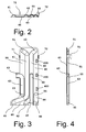
- the heat unit comprises a temperature sensor portion 55 (not shown in Fig. 1 but in Figs. 2, 3 and 4 ).
- a temperature sensor 4 (see Fig. 13 ) is located in the temperature sensor portion for sensing the temperature of the discharged heat-absorbing liquid of the secondary circuit.
- the middle plate 20 and the end plate 40 comprise a respective receiving portion 25, 45, respectively, wherein a connector 85 for connecting a signal line 8 (see Fig. 13 ) to the temperature sensor 4 is located.
- fastening means 71, 72 each comprising a hook for fixing the heating unit to corresponding fastening means.
- the fastening means 71, 72 are embodied as hooks.
- the middle plate 20 and the end plate 40 are brazed together.
- the snap fit comprises a snap fit indent 200 in the middle plate 20 and a mating snap fit intent 400 in the end plate 40. If the snap fit is located in the plate heat exchanger portion 30, 50, respectively, as shown in the embodiment, the intents 200, 400 are provided such that the indents are facing away from the last plate of the plate heat exchanger. If the snap fit is provided in the extension portion 26, 46 of the middle plate and end plate, respectively, the indents can protrude to the plate heat exchanger also.
- the indents 200, 400 are dimensioned such that they smoothly fit into each other.
- Indent 200 may comprise protrusions and recesses.
- Indent 400 may comprise corresponding recesses and protrusions. They are dimensioned such that the indents 200 and 400 can snap into each other in order to provide a preliminary alignment before the brazing takes place.
- the connector 83 is connected to a regulator 3.
- the regulator 3 is connected to a connection pipe having a connector 83a to be connected to a heat-emitting discharge line (not shown).
- a safety valve 5 As shown in Fig. 13 , in the heat-absorbing liquid supply channel 64 and/or the heat-absorbing liquid supply line there may be provided a safety valve 5, a closing valve 6 and/or a non-return valve 7.
- heat-emitting liquid supply channel 161 and heat-absorbing liquid discharge channel 162 are curved such that they have a greater extension.
- heat-emitting liquid supply channel 161 comprises a first heat-emitting liquid supply channel section 161a and a second heat-emitting liquid supply channel section 161b having a bent between each other and are extending in opposite directions.
- heat-absorbing liquid discharge channel 162 comprises a first heat-absorbing liquid discharge channel section 162a and a second heat-absorbing liquid discharge channel section 162b having a bent between each other and are extending in opposite directions. Due to this design the heat transfer between liquid supply channel 161 and liquid discharge channel 162 can be enhanced due to the greater extend of the channels.
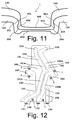
- Figs. 11 to 16 differs from the embodiment as shown in Figs. 1 to 10 , 13 and 15 in that the end plate 140 and the middle plate 120 are clinched together by means of clinch joints 1.
- the locations of the clinch joints 1 are indicated in Figs. 12 and Fig. 14 although the clinch joints are made only at the time the end plate and the middle plate are fixed together by clinching in order to define the correct alignment before the brazing step takes place.
- Figs. 12 and 14 the positions for the clinch joints 1 are indicated on the end plate 140 and the middle plate 120.
- the clinch joints 1 are made by punching two sheet of material (i.e. the end plate and the middle plate) into a die resulting in a clinch joint 1.
- An exemplary section of a clinch joint is shown in Fig. 11 .
- a clinch joint is shown, wherein the punch is made from the end plate in the direction of the middle plate 120, wherein a die (not shown) has been provided beneath the middle plate. It is clear that the punch can also been made the other way round, i.e. from the middle plate into the direction of the end plate resulting to a similar form as shown in Fig. 11 , wherein the clinch joint faces away from the end plate.
- the outer form of the clinch joint 1 corresponds to the form of the die (middle plate 120) and the punching stamp (end plate 140).
- the punch and the corresponding die forces the sheet material of the end plate 140 and the middle plate 120 into interlocking interference.
- protrusions 201, 203 of the middle plate 120 protruding into corresponding recesses 401, 403 of the end plate 140.
- protrusions 402, 404 of the end plate 140 protruding into corresponding recesses 202, 204 of the middle plate 120.
- the end plate may be adjoined with the middle plate by other means, as for instance using rivets, bolts etc. or gluing the plates together.
- the clinching is the preferred mode of fixing the relative position of the end plate and the middle plate.
- the clinch joints are to be made preferably in areas outside the area where the heat exchanger plates are to be located.
- two clinch joint 1 are to be located on the left hand side on each side of receiving portion 145.
- Another two clinch joints are located on the right hand side on each side of receiving portion 145.
- At the bottom side there are two clinch joints located in between receiving portions 141 and 142 as well as in between receiving portions 142 and 144.
- Different numbers and locations of clinch joints 1 are envisaged. For instance there may be three or two clinch joints provided only.
- the preferred method for manufacturing a heating unit in accordance with the invention is as follows:
Landscapes
- Engineering & Computer Science (AREA)
- Physics & Mathematics (AREA)
- Thermal Sciences (AREA)
- Mechanical Engineering (AREA)
- General Engineering & Computer Science (AREA)
- Heat-Exchange Devices With Radiators And Conduit Assemblies (AREA)
Priority Applications (1)
| Application Number | Priority Date | Filing Date | Title |
|---|---|---|---|
| EP09006353A EP2251631A1 (de) | 2009-05-11 | 2009-05-11 | Heizvorrichtung und Verfahren zu deren Herstellung |
Applications Claiming Priority (1)
| Application Number | Priority Date | Filing Date | Title |
|---|---|---|---|
| EP09006353A EP2251631A1 (de) | 2009-05-11 | 2009-05-11 | Heizvorrichtung und Verfahren zu deren Herstellung |
Publications (1)
| Publication Number | Publication Date |
|---|---|
| EP2251631A1 true EP2251631A1 (de) | 2010-11-17 |
Family
ID=41166374
Family Applications (1)
| Application Number | Title | Priority Date | Filing Date |
|---|---|---|---|
| EP09006353A Withdrawn EP2251631A1 (de) | 2009-05-11 | 2009-05-11 | Heizvorrichtung und Verfahren zu deren Herstellung |
Country Status (1)
| Country | Link |
|---|---|
| EP (1) | EP2251631A1 (de) |
Cited By (2)
| Publication number | Priority date | Publication date | Assignee | Title |
|---|---|---|---|---|
| KR101878247B1 (ko) * | 2016-08-30 | 2018-07-13 | 케이티씨 주식회사 | 세대형 열교환기 장치 및 그 설치방법 |
| DE102012113191B4 (de) | 2012-10-05 | 2025-12-04 | Hyundai Motor Company | Wärmetauscher für ein Fahrzeug |
Citations (4)
| Publication number | Priority date | Publication date | Assignee | Title |
|---|---|---|---|---|
| US5042577A (en) * | 1989-03-09 | 1991-08-27 | Aisin Seiki Kabushiki Kaisha | Evaporator |
| JP2004100982A (ja) * | 2002-09-05 | 2004-04-02 | Denso Corp | 熱交換器 |
| EP1500896A2 (de) | 2003-07-23 | 2005-01-26 | Invensys Process Systems A/S | Koppelelement für Wärmetauscher |
| US20050205236A1 (en) * | 2004-01-31 | 2005-09-22 | Klaus Kalbacher | Plate heat exchanger |
-
2009
- 2009-05-11 EP EP09006353A patent/EP2251631A1/de not_active Withdrawn
Patent Citations (4)
| Publication number | Priority date | Publication date | Assignee | Title |
|---|---|---|---|---|
| US5042577A (en) * | 1989-03-09 | 1991-08-27 | Aisin Seiki Kabushiki Kaisha | Evaporator |
| JP2004100982A (ja) * | 2002-09-05 | 2004-04-02 | Denso Corp | 熱交換器 |
| EP1500896A2 (de) | 2003-07-23 | 2005-01-26 | Invensys Process Systems A/S | Koppelelement für Wärmetauscher |
| US20050205236A1 (en) * | 2004-01-31 | 2005-09-22 | Klaus Kalbacher | Plate heat exchanger |
Cited By (2)
| Publication number | Priority date | Publication date | Assignee | Title |
|---|---|---|---|---|
| DE102012113191B4 (de) | 2012-10-05 | 2025-12-04 | Hyundai Motor Company | Wärmetauscher für ein Fahrzeug |
| KR101878247B1 (ko) * | 2016-08-30 | 2018-07-13 | 케이티씨 주식회사 | 세대형 열교환기 장치 및 그 설치방법 |
Similar Documents
| Publication | Publication Date | Title |
|---|---|---|
| EP2084481B1 (de) | Plattenwärmetauscher | |
| US7461689B2 (en) | Thermal cycling resistant tube to header joint for heat exchangers | |
| EP2676094B1 (de) | Herstellungsverfahren für wärmetauscher und wärmetauscher | |
| TW201017086A (en) | Heat exchanger | |
| US20040256083A1 (en) | Plate-type heat exchanger with single-walled and double-walled heat transfer plates | |
| AU594234B2 (en) | Convector/radiator construction | |
| US7204297B2 (en) | Plate-type heat exchanger with double-walled heat transfer plates | |
| EP2251631A1 (de) | Heizvorrichtung und Verfahren zu deren Herstellung | |
| AU647511B2 (en) | Heat exchanger | |
| CN206410590U (zh) | Hv换热板和高效板式换热器 | |
| EP2815198B1 (de) | Plattenwärmetauscher mit verbesserter festigkeit im verbindungsbereich | |
| WO2015193023A1 (en) | A heater and a heat exchanger installation | |
| EP2045554A2 (de) | Heizung mit hoch wirksamer Heizplatte | |
| KR101468607B1 (ko) | 하이브리드 반용접형 주전열면 열교환기 | |
| JP4633708B2 (ja) | プレート式熱交換器、及びプレート式熱交換器の製造方法 | |
| EP3821192B1 (de) | Plattenwärmetauscher mit verstärkten köpfen und verfahren zu ihrer herstellung und zusammenbau | |
| CN110506190A (zh) | 变压器散热器 | |
| WO2011039563A1 (en) | A heat exchanger | |
| EP2057434B1 (de) | Wärmetauscher ohne endkammern mit abwechselnden platten | |
| CN222951575U (zh) | 一种具有独立水盒的换热装置 | |
| EP1500896A2 (de) | Koppelelement für Wärmetauscher | |
| EP3569963B1 (de) | Sammelkasten für einen wärmetauscher | |
| CN212567015U (zh) | 一种高效的金属换热器 | |
| EP1361405A2 (de) | Wärmetauscher und Verfahren zu dessen Herstellung | |
| JP2004093064A (ja) | 熱交換器 |
Legal Events
| Date | Code | Title | Description |
|---|---|---|---|
| PUAI | Public reference made under article 153(3) epc to a published international application that has entered the european phase |
Free format text: ORIGINAL CODE: 0009012 |
|
| AK | Designated contracting states |
Kind code of ref document: A1 Designated state(s): AT BE BG CH CY CZ DE DK EE ES FI FR GB GR HR HU IE IS IT LI LT LU LV MC MK MT NL NO PL PT RO SE SI SK TR |
|
| AX | Request for extension of the european patent |
Extension state: AL BA RS |
|
| 17P | Request for examination filed |
Effective date: 20110415 |
|
| 17Q | First examination report despatched |
Effective date: 20110512 |
|
| STAA | Information on the status of an ep patent application or granted ep patent |
Free format text: STATUS: THE APPLICATION IS DEEMED TO BE WITHDRAWN |
|
| 18D | Application deemed to be withdrawn |
Effective date: 20111123 |