EP2251679A1 - Dispositif et procédé de mesure d'une caractéristique de produit à l'aide d'un agencement de capteur de champ de dispersion à micro-ondes - Google Patents
Dispositif et procédé de mesure d'une caractéristique de produit à l'aide d'un agencement de capteur de champ de dispersion à micro-ondes Download PDFInfo
- Publication number
- EP2251679A1 EP2251679A1 EP09006331A EP09006331A EP2251679A1 EP 2251679 A1 EP2251679 A1 EP 2251679A1 EP 09006331 A EP09006331 A EP 09006331A EP 09006331 A EP09006331 A EP 09006331A EP 2251679 A1 EP2251679 A1 EP 2251679A1
- Authority
- EP
- European Patent Office
- Prior art keywords
- product
- microwave
- resonator
- measured value
- property
- Prior art date
- Legal status (The legal status is an assumption and is not a legal conclusion. Google has not performed a legal analysis and makes no representation as to the accuracy of the status listed.)
- Granted
Links
Images


Classifications
-
- G—PHYSICS
- G01—MEASURING; TESTING
- G01N—INVESTIGATING OR ANALYSING MATERIALS BY DETERMINING THEIR CHEMICAL OR PHYSICAL PROPERTIES
- G01N22/00—Investigating or analysing materials by the use of microwaves or radio waves, i.e. electromagnetic waves with a wavelength of one millimetre or more
- G01N22/04—Investigating moisture content
Definitions
- the invention relates to a device and a method for measuring a property, in particular the moisture, density and / or mass, of a product by means of a microwave stray field sensor arrangement.
- a measuring device according to the preamble of claim 1 is known, wherein evaluated for at least two resonant modes with mutually different resonant frequencies in each case a shift in the resonant frequency and from a density-independent humidity value is calculated.
- the resonance frequency shift over the frequency is less sensitive to the humidity compared to the method described above, the measurement accuracy is significantly reduced in this method.
- the object of the invention is to provide a measuring device and a measuring method which enable the measurement of a product property with high measuring accuracy over a large moisture range by simple means.
- the invention solves this problem with the means of the independent claims. It has been found that in the inventive determination of the product characteristic as a function of at least one measured value associated with the attenuation of the first working mode and a measured value associated with the attenuation of the second working mode, there is a monotonic dependence on the moisture even with significantly higher moisture values and therefore a clear measurement for product humidities above 20% is possible. Since the change in attenuation over the frequency depends very sensitively on the humidity, the extension of the measuring range to humidities above 20% is essentially possible without any loss of the measuring accuracy. This is surprising for the stray field sensor arrangement according to the invention, because in this case microwave losses due to radiation in the far field are generally not negligible and mainly result from an increase in the width of the resonance curve.
- a measured value related to the attenuation of a working mode may be a width, an amplitude of the resonance curve, a slope in a slope of the resonance curve, a suitable combination thereof, or any other measurement independent of the frequency shift that suitably characterizes a change of the resonance curve.
- Measurements associated with microwave attenuation can be easily and quickly determined, for example, by means of two oscillating circuits which oscillate at different natural frequencies and measurement of the oscillation amplitudes.
- a complex Frequenzabtastung is therefore not mandatory for the implementation of the invention.
- the product property to be determined may be, for example, the moisture, density and / or mass of the product.
- the invention can be easily transferred to the determination of another substance in a product.
- the invention may preferably be used for measurement on a rod, rod, or tablet product.
- a preferred application relates to the online measurement on a product treated in a product treatment device, in particular a dryer, for example a fluidized-bed dryer.
- the invention therefore comprises the preferred combination of a measuring device with a product treatment device and Preferably, the control and / or regulation of the product treatment device as a function of a measurement result provided by the measuring device.
- the invention is not limited to specific product treatment, particularly drying, but is applicable to other product processing / handling / manufacturing methods and apparatus.
- all working modes are influenced by a product arranged in the product space.
- the modes of operation are particularly chosen so that each mode of operation undergoes significant microwave attenuation and resonant frequency shift due to coupling to the product.
- the invention is delimited from those conventional measuring devices in which a mode (empty mode) is chosen so that it does not substantially couple to the product and therefore experiences substantially no microwave attenuation and resonance frequency shift.
- a mode empty mode
- Such an empty mode may be useful for compensating for influences on the measurement signal that are not caused by the product, however, because of the lack of coupling to the product, an empty mode can in principle make no contribution to the determination of a product property.
- the invention relates to the measurement of a product property by means of at least one stray field sensor having at least one stray field resonator.
- a stray field resonator is an open resonator, wherein microwaves generated in the resonator exit through a resonator opening into the product space in order to interact with a product located in the product space Interacting.
- the product space is arranged outside the resonator or is not enclosed by it.
- an annular stray field resonator the product does not pass through the ring, but approximately perpendicular to the ring axis along the ring.
- the microwave frequencies used are preferably in the range above 10 MHz, more preferably above 100 MHz, more preferably above 1 GHz in order to reduce or substantially eliminate the influence of the ionic conductivity on the measurement signal. Furthermore, the microwave frequencies used are preferably in the range below 50 GHz, more preferably below 30 GHz, more preferably below the relaxation frequency of free water, i. Below 22 GHz, because at higher frequencies, the frequency dependence decreases with the attenuation of related measurements.
- the working modes preferably have a frequency spacing of at least 100 MHz, preferably at least 500 MHz, more preferably at least 1 GHz, further preferably at least 3 GHz, in order to obtain the greatest possible difference in the frequency dependence of the measured values of the two working modes and thus the highest possible measuring sensitivity.
- the frequency is at least one working mode above 3 GHz, more preferably above 3.5 GHz, more preferably above 5 GHz, more preferably above 7 GHz, since it has been shown that in these higher frequency ranges depending on the binding state of the water in the material to be measured has a pronounced frequency dependence with the attenuation of related measured values.
- the frequency of at least one working mode is preferably below 7 GHz, more preferably below 5 GHz, further preferably below 3.5 GHz in order to allow the most accurate measurement possible at low humidities.
- the resonant frequency of a work mode is an integer multiple of the resonant frequency of the other work mode, which can simplify the generation of the work modes, in particular by generating a fundamental mode and a higher mode by frequency multiplication.
- the evaluation device for determining product moistures of more than 20%, preferably more than 30%, more preferably more than 40%, is preferably set up from the measured values associated with the damping in order to enable the product property to be determined quickly and accurately up to high product moistures .
- curves obtained expediently from calibration measurements are stored in the evaluation device which correlate the product property to be determined and a measured variable calculated from the measured values over a moisture range of 0% to more than 20%, preferably to more than 30%, more preferably to more than 40 % specify.
- such curves obtained from calibration measurements only cover a humidity range of 0% to a maximum of 20%.
- the evaluation device for determining the product property can be set up in additional dependence on the frequency shift of a working mode or both working modes. As a result, the measurement accuracy may be increased under certain circumstances.
- the measuring device 24 comprises a control / evaluation unit 20 and a microwave stray field sensor arrangement 25.
- the microwave stray field sensor arrangement 25 comprises a microwave stray field sensor 1 comprising a microwave resonator 7.
- the stray field sensor 1 consists essentially of a carrier 2, which has an annular, in particular rectangular cross-section groove 6, in which preferably an annular dielectric 3 is fitted.
- the groove 6 or the dielectric 3 inserted therein forms the microwave resonator 7.
- the carrier 2 may be made of metal, for example stainless steel. or the walls of the carrier 2 forming the groove 6 may be metallized, or the surfaces of the dielectric 3 up to the measuring side can be metallised.
- the measuring-side surfaces 11a, 11b of the carrier 2 and the measuring-side surface 8 of the dielectric 3 form a continuous planar measuring surface 27.
- the sensor 1 is therefore a planar sensor.
- the microwave resonator 7 is preferably filled with a dielectric 3, which preferably has a dielectric constant of at least 1.5, preferably at least three, more preferably at least five, in order to reduce radiation losses.
- the dielectric 3 consists for example of aluminum oxide or another ceramic substance.
- Microwaves are generated in a microwave generating device 21, which may be controlled by an electronic control / evaluation device 23 by means of software.
- the programmable electronic control / evaluation device 23 comprises in particular a microprocessor or microcontroller.
- the microwave generating device 21 is designed to generate microwaves with frequencies above 10 MHz, in particular in the GHz range. In particular, microwaves of at least two different frequencies are generated which have a frequency spacing of preferably at least 100 MHz, more preferably at least 500 MHz, more preferably at least 1 GHz, and tuned to corresponding natural frequencies of the microwave resonator 7.
- the microwave generating device 21 may comprise either a plurality of microwave generators, or, for example, a microwave generator for generating a fundamental frequency and means for generating a further frequency from the fundamental frequency.
- One of the operating frequencies is preferably in the range of 2 GHz to 7 GHz and the other operating frequency is preferably in the range of 5 GHz to 22 GHz.
- the work modes may be generated simultaneously in the stray field sensor array 25. Alternatively, the working modes can be generated constantly alternately, so that there is only one working mode at any one time.
- the microwaves generated in the microwave generating device 21 are conducted via a microwave line 25 to the stray field sensor 1 and coupled to a corresponding terminal 4 in the microwave resonator 7. Due to the frequency tuning of the injected microwave field to certain natural frequencies of the resonator 7, standing in the resonator 7 standing microwave fields.
- the feeding of a microwave field with a second frequency leads to the formation of six wavelengths along the longitudinal axis A of the ring resonator 7 (second working mode); the intensity maxima I 2 corresponding to the twelve half-waves, ie the regions I 2, in which the intensity is, for example, greater than 50% of the maximum value, are indicated as dash-dotted circles.
- the frequencies of the microwave field are tuned to the formation of n1, n2 (possibly n3, ...) wavelengths along the ring resonator 7, where n1, n2 (optionally n3, ...) different integers greater than or equal to one, im
- a reduced microwave radiation preferably greater than or equal to three, more preferably greater or are five.
- the depth, width and optionally the shape of the groove 6 is selected so that the groove 6 represents a compromise with respect to the optimal propagation of the first working mode and the second operating mode in the resonator 7.
- the microwave field extends through the exit surface, ie the surface 8 of the dielectric 3 facing the product space, into the product space 9.
- Some field lines 12 of the microwave stray field are shown in FIG Fig. 1 indicated.
- the measuring arrangement 24 for continuous measurement is set up on a product 10 continuously guided past the measuring surface of the sensor 1.
- the product 10 is an arbitrary solid or liquid material, which basically can be oriented arbitrarily in the product space 9.
- a microwave signal is coupled out of the resonator 7 and fed via a microwave line 26 to an analyzer 22 whose output signal is processed or evaluated by the control / evaluation device 23.
- the microwave generating device 21, the analyzer 22 and the control / evaluation device 23 may be combined in a control / evaluation unit 20.
- the interaction of the microwave scattering field with the product 10 causes a change in the decoupled microwave signal, from which, by suitable evaluation, at least one measured variable M correlating with the product property to be determined; M1, M2 can be determined, as will be explained below.
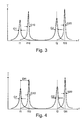
- Fig. 3 is an intensity spectrum of the coupled-out microwave field over the frequency shown, for example, the in Fig. 2 shown microwave field can correspond.
- the solid curve shows the actual measurement signal at the loaded with the product 10 microwave resonator 7 again.
- the dashed curve corresponds to an empty measurement with unloaded microwave resonator 7 and is shown here only for better understanding.
- Blank values for example the half-value widths G10, G20 or the frequencies f10, f20, can be determined in idle measurements before the actual measurement process and stored, for example, in the form of temperature profiles, in order then to be retrievable during the measurement.
- both resonance curves of the loaded resonator 7 are shifted relative to the respective resonance curves of the unloaded resonator 7 to lower frequencies and have due to the microwave attenuation by the product larger widths and lower amplitudes.
- the control / evaluation device 23 is now set up to determine a measured value G1 associated with the microwave attenuation of the first working mode and a measured value G2 related to the microwave attenuation of the second operating mode.
- these are the half-widths, but it can also be a different width, an amplitude, an edge slope, a combination thereof, or any other suitable size.
- control / evaluation unit 23 is for driving the microwave generating device 21 for performing scans over corresponding frequency ranges in the resonance curves set, which are sufficient to determine the measured quantities, here the half-widths.
- the control / evaluation device 23 calculates a suitable measured variable M as a function of the determined measured values G1 and G2 on the basis of a predetermined suitable relationship M (G1, G2) stored in the control / evaluation device 23.
- a curve E (M) obtained from calibration measurements is stored for each product to be measured, indicating a clear relationship between the product characteristic E to be determined and the measured variable M.
- the curves E (M) obtained from calibration measurements preferably extend over a moisture range of 0% to at least 20%, preferably to at least 30%, more preferably to at least 40%, for example to 50% and more.
- the desired product characteristic E can be calculated unambiguously from the measured quantity M determined immediately.
- the frequency shift Dfi of a working mode is determined and used in the determination of the product property. This can be done by determining the measurand M in additional dependence M (G1, G2, Dfi) on the frequency shift Dfi.
- the measured variable M (G1, G2) can be calculated without consideration of the frequency shift Dfi and, depending on the result for M, if appropriate, a further measurand M (Gi, Dfi) is calculated, which is then used for the determination of the product property.
- the measured variable M (G1, Df1) may enable an even more accurate determination of the product property at relatively low product moisture.
- the frequency shifts Df1 and Df2 of the first and second operating modes are determined and used in the determination of the product characteristic. This can be done by determining the measurand M in additional dependence M (G1, G2, Df1, Df2) on the frequency shifts Df1 and Df2.
- M the measured variable M
- G1, G2 the measured variable M
- M the measured variable M
- G1, Df1 or M G2, DF2
- Another alternative is to determine measured variables M1 (G1, Df1) and M2 (G2, DF2) and to use this to determine the product characteristic which leads to the same result for both measured quantities.
- resonators 7a, 7b may be provided for generating a respective working mode.
- Fig. 6 shows an embodiment with two annular, in particular concentrically arranged resonators 7a, 7b, which are preferably each filled with a dielectric ring 3a, 3b.
- a microwave field tuned to a specific natural frequency of the outer resonator 7a is fed via a line 25a into the outer resonator and to generate the first operating mode a microwave field is tuned to a corresponding natural frequency of the inner resonator 7b via a line 25b into the inner cavity Resonator 7b coupled.
- each resonator 7a, 7b can be optimally tuned to the propagation of the respective working mode, in particular by adaptation of the depth, width and possibly shape of the groove 6.
- the stray field sensor 1 may have a temperature sensor, not shown, for example, on the side of the dielectric 3 facing away from the measurement side 27, the signal of which can be used by the control / evaluation device 23 to compensate for temperature effects.
- the stray field sensor 1 can also be used as a microstrip conductor, for example according to EP 1 331 476 B1 with or without Referenzresonator, or be carried out in another way suitable.
- the sensor arrangement 25 may comprise a plurality of stray field sensors 1, for example two stray field sensors 1 for generating a respective working mode.
Landscapes
- Physics & Mathematics (AREA)
- Electromagnetism (AREA)
- Health & Medical Sciences (AREA)
- Life Sciences & Earth Sciences (AREA)
- Chemical & Material Sciences (AREA)
- Analytical Chemistry (AREA)
- Biochemistry (AREA)
- General Health & Medical Sciences (AREA)
- General Physics & Mathematics (AREA)
- Immunology (AREA)
- Pathology (AREA)
- Measurement Of Resistance Or Impedance (AREA)
Priority Applications (1)
| Application Number | Priority Date | Filing Date | Title |
|---|---|---|---|
| EP20090006331 EP2251679B9 (fr) | 2009-05-11 | 2009-05-11 | Dispositif et procédé de mesure d'une caractéristique de produit à l'aide d'un agencement de capteur de champ de dispersion à micro-ondes |
Applications Claiming Priority (1)
| Application Number | Priority Date | Filing Date | Title |
|---|---|---|---|
| EP20090006331 EP2251679B9 (fr) | 2009-05-11 | 2009-05-11 | Dispositif et procédé de mesure d'une caractéristique de produit à l'aide d'un agencement de capteur de champ de dispersion à micro-ondes |
Publications (3)
| Publication Number | Publication Date |
|---|---|
| EP2251679A1 true EP2251679A1 (fr) | 2010-11-17 |
| EP2251679B1 EP2251679B1 (fr) | 2012-10-24 |
| EP2251679B9 EP2251679B9 (fr) | 2013-01-09 |
Family
ID=41395016
Family Applications (1)
| Application Number | Title | Priority Date | Filing Date |
|---|---|---|---|
| EP20090006331 Active EP2251679B9 (fr) | 2009-05-11 | 2009-05-11 | Dispositif et procédé de mesure d'une caractéristique de produit à l'aide d'un agencement de capteur de champ de dispersion à micro-ondes |
Country Status (1)
| Country | Link |
|---|---|
| EP (1) | EP2251679B9 (fr) |
Cited By (4)
| Publication number | Priority date | Publication date | Assignee | Title |
|---|---|---|---|---|
| DE102016212973A1 (de) | 2016-07-15 | 2018-01-18 | Conti Temic Microelectronic Gmbh | Umfeldsensor mit Resonator zur Detektion einer Sensordegradation |
| RU2641715C1 (ru) * | 2017-02-27 | 2018-01-22 | федеральное государственное бюджетное образовательное учреждение высшего образования "Самарская государственная сельскохозяйственная академия" | СВЧ-устройство для измерения влажности почвы |
| RU2769954C1 (ru) * | 2021-12-01 | 2022-04-11 | Общество с ограниченной ответственностью "НАФТА-СПЕКТР" | Способ измерения влагосодержания в водонефтяных смесях и устройство для его реализации |
| CN114354740A (zh) * | 2022-03-09 | 2022-04-15 | 成都熊谷油气科技有限公司 | 一种管道检测系统 |
Families Citing this family (2)
| Publication number | Priority date | Publication date | Assignee | Title |
|---|---|---|---|---|
| DE102015110491B3 (de) * | 2015-06-30 | 2016-08-18 | Work Microwave Gmbh | Vorrichtung, verfahren zur ermittlung einer für ein objekt charakteristischen grösse |
| DE102017122809B3 (de) | 2017-09-29 | 2019-01-10 | Christian-Albrechts-Universität Zu Kiel | Filtereinrichtung mit Mikrowellenresonator |
Citations (8)
| Publication number | Priority date | Publication date | Assignee | Title |
|---|---|---|---|---|
| DE2928487A1 (de) | 1979-07-14 | 1981-02-05 | Philips Patentverwaltung | Verfahren zur messung der relativen feuchte eines messgutes mit hilfe von mikrowellen im ghz-bereich |
| DE4004119A1 (de) * | 1990-02-10 | 1991-08-14 | Tews Elektronik Dipl Ing Manfr | Verfahren zur messung der feuchte eines messgutes mit hilfe von mikrowellen und vorrichtung zur durchfuehrung des verfahrens |
| EP1321564A1 (fr) * | 2001-12-21 | 2003-06-25 | BSH Bosch und Siemens Hausgeräte GmbH | Appareil de traitement du linge avec une capteur d'humité et procédé pour la détermination de la teneur en humidité du linge |
| EP1437588A1 (fr) * | 2003-01-10 | 2004-07-14 | AMS- Advanced Microwave Systems GmbH | Détecteur de champ de dispersion des micro-ondes |
| DE202005010375U1 (de) * | 2005-07-01 | 2005-10-20 | Tews Elektronik Dipl.-Ing. Manfred Tews | Vorrichtung zum Detektieren und Aussondern von fehlerhaften Zigaretten |
| EP1331476B1 (fr) | 2002-01-29 | 2006-04-26 | AMS- Advanced Microwave Systems GmbH | Appareil à micro-ondes pour des mesures de l'humidité, avec compensation de température |
| DE102005013647B3 (de) * | 2005-03-24 | 2006-08-24 | Keller Hcw Gmbh | Verfahren und Vorrichtung zur Messung der Materialfeuchte eines Meßgutes |
| WO2009030314A1 (fr) | 2007-08-28 | 2009-03-12 | Tews Elektronik | Procédé et dispositif de mesure d'une valeur d'humidité indépendante de la densité et d'une valeur de densité de matériaux diélectriques à partir des décalages de fréquence entre deux résonateurs hyperfréquence ou deux modes d'un résonateur hyperfréquence |
-
2009
- 2009-05-11 EP EP20090006331 patent/EP2251679B9/fr active Active
Patent Citations (9)
| Publication number | Priority date | Publication date | Assignee | Title |
|---|---|---|---|---|
| DE2928487A1 (de) | 1979-07-14 | 1981-02-05 | Philips Patentverwaltung | Verfahren zur messung der relativen feuchte eines messgutes mit hilfe von mikrowellen im ghz-bereich |
| DE4004119A1 (de) * | 1990-02-10 | 1991-08-14 | Tews Elektronik Dipl Ing Manfr | Verfahren zur messung der feuchte eines messgutes mit hilfe von mikrowellen und vorrichtung zur durchfuehrung des verfahrens |
| EP1321564A1 (fr) * | 2001-12-21 | 2003-06-25 | BSH Bosch und Siemens Hausgeräte GmbH | Appareil de traitement du linge avec une capteur d'humité et procédé pour la détermination de la teneur en humidité du linge |
| EP1331476B1 (fr) | 2002-01-29 | 2006-04-26 | AMS- Advanced Microwave Systems GmbH | Appareil à micro-ondes pour des mesures de l'humidité, avec compensation de température |
| EP1437588A1 (fr) * | 2003-01-10 | 2004-07-14 | AMS- Advanced Microwave Systems GmbH | Détecteur de champ de dispersion des micro-ondes |
| EP1437588B1 (fr) | 2003-01-10 | 2005-08-31 | AMS- Advanced Microwave Systems GmbH | Détecteur de champ de dispersion des micro-ondes |
| DE102005013647B3 (de) * | 2005-03-24 | 2006-08-24 | Keller Hcw Gmbh | Verfahren und Vorrichtung zur Messung der Materialfeuchte eines Meßgutes |
| DE202005010375U1 (de) * | 2005-07-01 | 2005-10-20 | Tews Elektronik Dipl.-Ing. Manfred Tews | Vorrichtung zum Detektieren und Aussondern von fehlerhaften Zigaretten |
| WO2009030314A1 (fr) | 2007-08-28 | 2009-03-12 | Tews Elektronik | Procédé et dispositif de mesure d'une valeur d'humidité indépendante de la densité et d'une valeur de densité de matériaux diélectriques à partir des décalages de fréquence entre deux résonateurs hyperfréquence ou deux modes d'un résonateur hyperfréquence |
Non-Patent Citations (2)
| Title |
|---|
| K. KUPFER: "nMaterialfeuchtemessung", 1997, EXPERT VERLAG, pages: 145 - 154 |
| REINHARD KNÖCHEL ET AL: "Stray field ring resonators and a novel trough guide resonator for precise microwave moisture and density measurements; Stray field ring resonators for microwave moisture and density measurements", MEASUREMENT SCIENCE AND TECHNOLOGY, IOP, BRISTOL, GB, vol. 18, no. 4, 1 April 2007 (2007-04-01), pages 1061 - 1068, XP020118588, ISSN: 0957-0233 * |
Cited By (5)
| Publication number | Priority date | Publication date | Assignee | Title |
|---|---|---|---|---|
| DE102016212973A1 (de) | 2016-07-15 | 2018-01-18 | Conti Temic Microelectronic Gmbh | Umfeldsensor mit Resonator zur Detektion einer Sensordegradation |
| RU2641715C1 (ru) * | 2017-02-27 | 2018-01-22 | федеральное государственное бюджетное образовательное учреждение высшего образования "Самарская государственная сельскохозяйственная академия" | СВЧ-устройство для измерения влажности почвы |
| RU2769954C1 (ru) * | 2021-12-01 | 2022-04-11 | Общество с ограниченной ответственностью "НАФТА-СПЕКТР" | Способ измерения влагосодержания в водонефтяных смесях и устройство для его реализации |
| CN114354740A (zh) * | 2022-03-09 | 2022-04-15 | 成都熊谷油气科技有限公司 | 一种管道检测系统 |
| CN114354740B (zh) * | 2022-03-09 | 2022-05-31 | 成都熊谷油气科技有限公司 | 一种管道检测系统 |
Also Published As
| Publication number | Publication date |
|---|---|
| EP2251679B1 (fr) | 2012-10-24 |
| EP2251679B9 (fr) | 2013-01-09 |
Similar Documents
| Publication | Publication Date | Title |
|---|---|---|
| DE4342505C1 (de) | Verfahren und Vorrichtung zur Messung der Dielektrizitätskonstante von Probenmaterialien | |
| EP1221608B1 (fr) | Méthode pour tester un matériau de production dans un champ de micro-ondes | |
| EP2251679B1 (fr) | Dispositif et procédé de mesure d'une caractéristique de produit à l'aide d'un agencement de capteur de champ de dispersion à micro-ondes | |
| EP2042858B1 (fr) | Dispositif résonateur à microondes de mesure | |
| EP0468023B1 (fr) | Procede d'evaluation de l'humidite d'un produit a l'aide de micro-ondes et dispositif d'execution du procede | |
| DE19705260B4 (de) | Anordnung zum Erfassen mindestens einer dielektrischen Eigenschaft eines Stoffes | |
| DE112007001465B4 (de) | Verfahren und Vorrichtung für eine Messung mittels hochfrequenter Strahlung | |
| EP0753755A2 (fr) | Dispositif de mesure de la constante diélectrique complexe du tabac | |
| EP3158325B1 (fr) | Dispositif de mesure à micro-ondes, ensemble et procédé de contrôle d'articles en forme de bâtonnet ou d'un boudin de matière issus de l'industrie de transformation du tabac, et machine de l'industrie de transformation du tabac | |
| DE2454788A1 (de) | Verfahren und vorrichtung zur feuchtigkeitsbestimmung eines gasfoermigen mediums | |
| EP1680662B1 (fr) | Procede de determination de l'humidite et de la densite d'un materiau dielectrique | |
| EP1321564A1 (fr) | Appareil de traitement du linge avec une capteur d'humité et procédé pour la détermination de la teneur en humidité du linge | |
| DE19734978A1 (de) | Verfahren und Anordnung zum Erfassen mindestens einer Eigenschaft eines Stoffes | |
| DE102007025815A1 (de) | Verfahren und Vorrichtung zur Messung wenigstens einer Qualitätsgröße einer Faserstoffbahn | |
| EP0902277A1 (fr) | Méthode et dispositif pour la détermination d'au moins une propriété d'un produit | |
| DE102009024203B4 (de) | Mikrowellensensor und Verfahren zur Bestimmung dielektrischer Materialeigenschaften | |
| DE102009054070A1 (de) | Verfahren und Einrichtung zum Messen der Lage eines in Paketen vorliegenden Teilchenstrahls in einem Linearbeschleuniger | |
| DE112006001212B4 (de) | Verfahren und Messgerät zur Messung von Wassergehalt | |
| EP1437588B1 (fr) | Détecteur de champ de dispersion des micro-ondes | |
| EP1321566A1 (fr) | Appareil de traitement du linge avec une capteur d'humité et procédé pour la détermination de la teneur en humidité du linge | |
| DE19520021A1 (de) | Verfahren und Vorrichtung zur Bestimmung der Dielektrizitätskonstanten in Gemengen oder Flüssigkeiten, insbesondere zur Feuchtigkeitsbestimmung im Erdboden | |
| DE102023117163A1 (de) | Gerät zur messung mindestens einer elektromagnetischen eigenschaft einer materialprobe | |
| EP4264242A1 (fr) | Procédé de mesure de quantités de substances dans un mélange de substances | |
| DE102023110650A1 (de) | Sensorkörper, Messvorrichtung und Verfahren zur Bestimmung hoher Luftfeuchten | |
| EP1564548A1 (fr) | Résonateur à hyperfréquence excité en modes plus hautes pour mésurer une propriété dielectrique d'un produit |
Legal Events
| Date | Code | Title | Description |
|---|---|---|---|
| PUAI | Public reference made under article 153(3) epc to a published international application that has entered the european phase |
Free format text: ORIGINAL CODE: 0009012 |
|
| 17P | Request for examination filed |
Effective date: 20100108 |
|
| AK | Designated contracting states |
Kind code of ref document: A1 Designated state(s): AT BE BG CH CY CZ DE DK EE ES FI FR GB GR HR HU IE IS IT LI LT LU LV MC MK MT NL NO PL PT RO SE SI SK TR |
|
| AX | Request for extension of the european patent |
Extension state: AL BA RS |
|
| GRAP | Despatch of communication of intention to grant a patent |
Free format text: ORIGINAL CODE: EPIDOSNIGR1 |
|
| GRAS | Grant fee paid |
Free format text: ORIGINAL CODE: EPIDOSNIGR3 |
|
| GRAA | (expected) grant |
Free format text: ORIGINAL CODE: 0009210 |
|
| AK | Designated contracting states |
Kind code of ref document: B1 Designated state(s): AT BE BG CH CY CZ DE DK EE ES FI FR GB GR HR HU IE IS IT LI LT LU LV MC MK MT NL NO PL PT RO SE SI SK TR |
|
| REG | Reference to a national code |
Ref country code: GB Ref legal event code: FG4D Free format text: NOT ENGLISH |
|
| REG | Reference to a national code |
Ref country code: CH Ref legal event code: EP |
|
| REG | Reference to a national code |
Ref country code: AT Ref legal event code: REF Ref document number: 581192 Country of ref document: AT Kind code of ref document: T Effective date: 20121115 |
|
| REG | Reference to a national code |
Ref country code: IE Ref legal event code: FG4D Free format text: LANGUAGE OF EP DOCUMENT: GERMAN |
|
| REG | Reference to a national code |
Ref country code: DE Ref legal event code: R096 Ref document number: 502009005153 Country of ref document: DE Effective date: 20121220 |
|
| REG | Reference to a national code |
Ref country code: NL Ref legal event code: VDEP Effective date: 20121024 |
|
| PG25 | Lapsed in a contracting state [announced via postgrant information from national office to epo] |
Ref country code: IS Free format text: LAPSE BECAUSE OF FAILURE TO SUBMIT A TRANSLATION OF THE DESCRIPTION OR TO PAY THE FEE WITHIN THE PRESCRIBED TIME-LIMIT Effective date: 20130224 Ref country code: HR Free format text: LAPSE BECAUSE OF FAILURE TO SUBMIT A TRANSLATION OF THE DESCRIPTION OR TO PAY THE FEE WITHIN THE PRESCRIBED TIME-LIMIT Effective date: 20121024 Ref country code: NL Free format text: LAPSE BECAUSE OF FAILURE TO SUBMIT A TRANSLATION OF THE DESCRIPTION OR TO PAY THE FEE WITHIN THE PRESCRIBED TIME-LIMIT Effective date: 20121024 Ref country code: ES Free format text: LAPSE BECAUSE OF FAILURE TO SUBMIT A TRANSLATION OF THE DESCRIPTION OR TO PAY THE FEE WITHIN THE PRESCRIBED TIME-LIMIT Effective date: 20130204 Ref country code: SE Free format text: LAPSE BECAUSE OF FAILURE TO SUBMIT A TRANSLATION OF THE DESCRIPTION OR TO PAY THE FEE WITHIN THE PRESCRIBED TIME-LIMIT Effective date: 20121024 Ref country code: NO Free format text: LAPSE BECAUSE OF FAILURE TO SUBMIT A TRANSLATION OF THE DESCRIPTION OR TO PAY THE FEE WITHIN THE PRESCRIBED TIME-LIMIT Effective date: 20130124 Ref country code: FI Free format text: LAPSE BECAUSE OF FAILURE TO SUBMIT A TRANSLATION OF THE DESCRIPTION OR TO PAY THE FEE WITHIN THE PRESCRIBED TIME-LIMIT Effective date: 20121024 |
|
| PG25 | Lapsed in a contracting state [announced via postgrant information from national office to epo] |
Ref country code: LV Free format text: LAPSE BECAUSE OF FAILURE TO SUBMIT A TRANSLATION OF THE DESCRIPTION OR TO PAY THE FEE WITHIN THE PRESCRIBED TIME-LIMIT Effective date: 20121024 Ref country code: PL Free format text: LAPSE BECAUSE OF FAILURE TO SUBMIT A TRANSLATION OF THE DESCRIPTION OR TO PAY THE FEE WITHIN THE PRESCRIBED TIME-LIMIT Effective date: 20121024 Ref country code: GR Free format text: LAPSE BECAUSE OF FAILURE TO SUBMIT A TRANSLATION OF THE DESCRIPTION OR TO PAY THE FEE WITHIN THE PRESCRIBED TIME-LIMIT Effective date: 20130125 Ref country code: SI Free format text: LAPSE BECAUSE OF FAILURE TO SUBMIT A TRANSLATION OF THE DESCRIPTION OR TO PAY THE FEE WITHIN THE PRESCRIBED TIME-LIMIT Effective date: 20121024 Ref country code: PT Free format text: LAPSE BECAUSE OF FAILURE TO SUBMIT A TRANSLATION OF THE DESCRIPTION OR TO PAY THE FEE WITHIN THE PRESCRIBED TIME-LIMIT Effective date: 20130225 |
|
| PLBI | Opposition filed |
Free format text: ORIGINAL CODE: 0009260 |
|
| PG25 | Lapsed in a contracting state [announced via postgrant information from national office to epo] |
Ref country code: CZ Free format text: LAPSE BECAUSE OF FAILURE TO SUBMIT A TRANSLATION OF THE DESCRIPTION OR TO PAY THE FEE WITHIN THE PRESCRIBED TIME-LIMIT Effective date: 20121024 Ref country code: DK Free format text: LAPSE BECAUSE OF FAILURE TO SUBMIT A TRANSLATION OF THE DESCRIPTION OR TO PAY THE FEE WITHIN THE PRESCRIBED TIME-LIMIT Effective date: 20121024 Ref country code: SK Free format text: LAPSE BECAUSE OF FAILURE TO SUBMIT A TRANSLATION OF THE DESCRIPTION OR TO PAY THE FEE WITHIN THE PRESCRIBED TIME-LIMIT Effective date: 20121024 Ref country code: EE Free format text: LAPSE BECAUSE OF FAILURE TO SUBMIT A TRANSLATION OF THE DESCRIPTION OR TO PAY THE FEE WITHIN THE PRESCRIBED TIME-LIMIT Effective date: 20121024 Ref country code: BG Free format text: LAPSE BECAUSE OF FAILURE TO SUBMIT A TRANSLATION OF THE DESCRIPTION OR TO PAY THE FEE WITHIN THE PRESCRIBED TIME-LIMIT Effective date: 20130124 |
|
| 26 | Opposition filed |
Opponent name: TEWS ELEKTRONIK GMBH & CO. KG Effective date: 20130724 |
|
| PG25 | Lapsed in a contracting state [announced via postgrant information from national office to epo] |
Ref country code: RO Free format text: LAPSE BECAUSE OF FAILURE TO SUBMIT A TRANSLATION OF THE DESCRIPTION OR TO PAY THE FEE WITHIN THE PRESCRIBED TIME-LIMIT Effective date: 20121024 Ref country code: IT Free format text: LAPSE BECAUSE OF FAILURE TO SUBMIT A TRANSLATION OF THE DESCRIPTION OR TO PAY THE FEE WITHIN THE PRESCRIBED TIME-LIMIT Effective date: 20121024 |
|
| PLAX | Notice of opposition and request to file observation + time limit sent |
Free format text: ORIGINAL CODE: EPIDOSNOBS2 |
|
| REG | Reference to a national code |
Ref country code: DE Ref legal event code: R026 Ref document number: 502009005153 Country of ref document: DE Effective date: 20130724 |
|
| PLBB | Reply of patent proprietor to notice(s) of opposition received |
Free format text: ORIGINAL CODE: EPIDOSNOBS3 |
|
| PG25 | Lapsed in a contracting state [announced via postgrant information from national office to epo] |
Ref country code: CY Free format text: LAPSE BECAUSE OF FAILURE TO SUBMIT A TRANSLATION OF THE DESCRIPTION OR TO PAY THE FEE WITHIN THE PRESCRIBED TIME-LIMIT Effective date: 20121024 |
|
| BERE | Be: lapsed |
Owner name: AMS- ADVANCED MICROWAVE SYSTEMS G.M.B.H. Effective date: 20130531 |
|
| PG25 | Lapsed in a contracting state [announced via postgrant information from national office to epo] |
Ref country code: MC Free format text: LAPSE BECAUSE OF FAILURE TO SUBMIT A TRANSLATION OF THE DESCRIPTION OR TO PAY THE FEE WITHIN THE PRESCRIBED TIME-LIMIT Effective date: 20121024 |
|
| REG | Reference to a national code |
Ref country code: CH Ref legal event code: PL |
|
| PG25 | Lapsed in a contracting state [announced via postgrant information from national office to epo] |
Ref country code: CH Free format text: LAPSE BECAUSE OF NON-PAYMENT OF DUE FEES Effective date: 20130531 Ref country code: LI Free format text: LAPSE BECAUSE OF NON-PAYMENT OF DUE FEES Effective date: 20130531 |
|
| REG | Reference to a national code |
Ref country code: IE Ref legal event code: MM4A |
|
| PG25 | Lapsed in a contracting state [announced via postgrant information from national office to epo] |
Ref country code: BE Free format text: LAPSE BECAUSE OF NON-PAYMENT OF DUE FEES Effective date: 20130531 |
|
| PG25 | Lapsed in a contracting state [announced via postgrant information from national office to epo] |
Ref country code: IE Free format text: LAPSE BECAUSE OF NON-PAYMENT OF DUE FEES Effective date: 20130511 |
|
| PG25 | Lapsed in a contracting state [announced via postgrant information from national office to epo] |
Ref country code: LT Free format text: LAPSE BECAUSE OF FAILURE TO SUBMIT A TRANSLATION OF THE DESCRIPTION OR TO PAY THE FEE WITHIN THE PRESCRIBED TIME-LIMIT Effective date: 20121024 |
|
| PG25 | Lapsed in a contracting state [announced via postgrant information from national office to epo] |
Ref country code: MT Free format text: LAPSE BECAUSE OF FAILURE TO SUBMIT A TRANSLATION OF THE DESCRIPTION OR TO PAY THE FEE WITHIN THE PRESCRIBED TIME-LIMIT Effective date: 20121024 |
|
| REG | Reference to a national code |
Ref country code: DE Ref legal event code: R100 Ref document number: 502009005153 Country of ref document: DE |
|
| PLCK | Communication despatched that opposition was rejected |
Free format text: ORIGINAL CODE: EPIDOSNREJ1 |
|
| PG25 | Lapsed in a contracting state [announced via postgrant information from national office to epo] |
Ref country code: TR Free format text: LAPSE BECAUSE OF FAILURE TO SUBMIT A TRANSLATION OF THE DESCRIPTION OR TO PAY THE FEE WITHIN THE PRESCRIBED TIME-LIMIT Effective date: 20121024 |
|
| RAP2 | Party data changed (patent owner data changed or rights of a patent transferred) |
Owner name: DOESCHER MICROWAVE SYSTEMS GMBH |
|
| REG | Reference to a national code |
Ref country code: AT Ref legal event code: MM01 Ref document number: 581192 Country of ref document: AT Kind code of ref document: T Effective date: 20140511 |
|
| PLBN | Opposition rejected |
Free format text: ORIGINAL CODE: 0009273 |
|
| STAA | Information on the status of an ep patent application or granted ep patent |
Free format text: STATUS: OPPOSITION REJECTED |
|
| PG25 | Lapsed in a contracting state [announced via postgrant information from national office to epo] |
Ref country code: MK Free format text: LAPSE BECAUSE OF FAILURE TO SUBMIT A TRANSLATION OF THE DESCRIPTION OR TO PAY THE FEE WITHIN THE PRESCRIBED TIME-LIMIT Effective date: 20121024 Ref country code: LU Free format text: LAPSE BECAUSE OF NON-PAYMENT OF DUE FEES Effective date: 20130511 Ref country code: HU Free format text: LAPSE BECAUSE OF FAILURE TO SUBMIT A TRANSLATION OF THE DESCRIPTION OR TO PAY THE FEE WITHIN THE PRESCRIBED TIME-LIMIT; INVALID AB INITIO Effective date: 20090511 |
|
| 27O | Opposition rejected |
Effective date: 20150320 |
|
| PG25 | Lapsed in a contracting state [announced via postgrant information from national office to epo] |
Ref country code: AT Free format text: LAPSE BECAUSE OF NON-PAYMENT OF DUE FEES Effective date: 20140511 |
|
| REG | Reference to a national code |
Ref country code: FR Ref legal event code: PLFP Year of fee payment: 8 |
|
| REG | Reference to a national code |
Ref country code: FR Ref legal event code: PLFP Year of fee payment: 9 |
|
| REG | Reference to a national code |
Ref country code: FR Ref legal event code: PLFP Year of fee payment: 10 |
|
| PGFP | Annual fee paid to national office [announced via postgrant information from national office to epo] |
Ref country code: FR Payment date: 20190507 Year of fee payment: 11 |
|
| PG25 | Lapsed in a contracting state [announced via postgrant information from national office to epo] |
Ref country code: FR Free format text: LAPSE BECAUSE OF NON-PAYMENT OF DUE FEES Effective date: 20200531 |
|
| PGFP | Annual fee paid to national office [announced via postgrant information from national office to epo] |
Ref country code: DE Payment date: 20250519 Year of fee payment: 17 |
|
| PGFP | Annual fee paid to national office [announced via postgrant information from national office to epo] |
Ref country code: GB Payment date: 20260324 Year of fee payment: 18 |