EP2251699B1 - Roulement, méthode pour sa fabrication et le couvercle associé. - Google Patents
Roulement, méthode pour sa fabrication et le couvercle associé. Download PDFInfo
- Publication number
- EP2251699B1 EP2251699B1 EP10174787.1A EP10174787A EP2251699B1 EP 2251699 B1 EP2251699 B1 EP 2251699B1 EP 10174787 A EP10174787 A EP 10174787A EP 2251699 B1 EP2251699 B1 EP 2251699B1
- Authority
- EP
- European Patent Office
- Prior art keywords
- cover
- sensor
- face
- ring
- flange
- Prior art date
- Legal status (The legal status is an assumption and is not a legal conclusion. Google has not performed a legal analysis and makes no representation as to the accuracy of the status listed.)
- Expired - Lifetime
Links
Images






Classifications
-
- F—MECHANICAL ENGINEERING; LIGHTING; HEATING; WEAPONS; BLASTING
- F16—ENGINEERING ELEMENTS AND UNITS; GENERAL MEASURES FOR PRODUCING AND MAINTAINING EFFECTIVE FUNCTIONING OF MACHINES OR INSTALLATIONS; THERMAL INSULATION IN GENERAL
- F16C—SHAFTS; FLEXIBLE SHAFTS; ELEMENTS OR CRANKSHAFT MECHANISMS; ROTARY BODIES OTHER THAN GEARING ELEMENTS; BEARINGS
- F16C19/00—Bearings with rolling contact, for exclusively rotary movement
- F16C19/02—Bearings with rolling contact, for exclusively rotary movement with bearing balls essentially of the same size in one or more circular rows
- F16C19/14—Bearings with rolling contact, for exclusively rotary movement with bearing balls essentially of the same size in one or more circular rows for both radial and axial load
- F16C19/18—Bearings with rolling contact, for exclusively rotary movement with bearing balls essentially of the same size in one or more circular rows for both radial and axial load with two or more rows of balls
- F16C19/181—Bearings with rolling contact, for exclusively rotary movement with bearing balls essentially of the same size in one or more circular rows for both radial and axial load with two or more rows of balls with angular contact
- F16C19/183—Bearings with rolling contact, for exclusively rotary movement with bearing balls essentially of the same size in one or more circular rows for both radial and axial load with two or more rows of balls with angular contact with two rows at opposite angles
- F16C19/184—Bearings with rolling contact, for exclusively rotary movement with bearing balls essentially of the same size in one or more circular rows for both radial and axial load with two or more rows of balls with angular contact with two rows at opposite angles in O-arrangement
- F16C19/186—Bearings with rolling contact, for exclusively rotary movement with bearing balls essentially of the same size in one or more circular rows for both radial and axial load with two or more rows of balls with angular contact with two rows at opposite angles in O-arrangement with three raceways provided integrally on parts other than race rings, e.g. third generation hubs
-
- B—PERFORMING OPERATIONS; TRANSPORTING
- B60—VEHICLES IN GENERAL
- B60B—VEHICLE WHEELS; CASTORS; AXLES FOR WHEELS OR CASTORS; INCREASING WHEEL ADHESION
- B60B27/00—Hubs
- B60B27/0005—Hubs with ball bearings
-
- B—PERFORMING OPERATIONS; TRANSPORTING
- B60—VEHICLES IN GENERAL
- B60B—VEHICLE WHEELS; CASTORS; AXLES FOR WHEELS OR CASTORS; INCREASING WHEEL ADHESION
- B60B27/00—Hubs
- B60B27/0047—Hubs characterised by functional integration of other elements
- B60B27/0068—Hubs characterised by functional integration of other elements the element being a sensor
-
- B—PERFORMING OPERATIONS; TRANSPORTING
- B60—VEHICLES IN GENERAL
- B60B—VEHICLE WHEELS; CASTORS; AXLES FOR WHEELS OR CASTORS; INCREASING WHEEL ADHESION
- B60B27/00—Hubs
- B60B27/0073—Hubs characterised by sealing means
-
- B—PERFORMING OPERATIONS; TRANSPORTING
- B60—VEHICLES IN GENERAL
- B60B—VEHICLE WHEELS; CASTORS; AXLES FOR WHEELS OR CASTORS; INCREASING WHEEL ADHESION
- B60B27/00—Hubs
- B60B27/0078—Hubs characterised by the fixation of bearings
- B60B27/0084—Hubs characterised by the fixation of bearings caulking to fix inner race
-
- B—PERFORMING OPERATIONS; TRANSPORTING
- B60—VEHICLES IN GENERAL
- B60B—VEHICLE WHEELS; CASTORS; AXLES FOR WHEELS OR CASTORS; INCREASING WHEEL ADHESION
- B60B27/00—Hubs
- B60B27/0094—Hubs one or more of the bearing races are formed by the hub
-
- F—MECHANICAL ENGINEERING; LIGHTING; HEATING; WEAPONS; BLASTING
- F16—ENGINEERING ELEMENTS AND UNITS; GENERAL MEASURES FOR PRODUCING AND MAINTAINING EFFECTIVE FUNCTIONING OF MACHINES OR INSTALLATIONS; THERMAL INSULATION IN GENERAL
- F16C—SHAFTS; FLEXIBLE SHAFTS; ELEMENTS OR CRANKSHAFT MECHANISMS; ROTARY BODIES OTHER THAN GEARING ELEMENTS; BEARINGS
- F16C33/00—Parts of bearings; Special methods for making bearings or parts thereof
- F16C33/72—Sealings
- F16C33/723—Shaft end sealing means, e.g. cup-shaped caps or covers
-
- F—MECHANICAL ENGINEERING; LIGHTING; HEATING; WEAPONS; BLASTING
- F16—ENGINEERING ELEMENTS AND UNITS; GENERAL MEASURES FOR PRODUCING AND MAINTAINING EFFECTIVE FUNCTIONING OF MACHINES OR INSTALLATIONS; THERMAL INSULATION IN GENERAL
- F16C—SHAFTS; FLEXIBLE SHAFTS; ELEMENTS OR CRANKSHAFT MECHANISMS; ROTARY BODIES OTHER THAN GEARING ELEMENTS; BEARINGS
- F16C41/00—Other accessories, e.g. devices integrated in the bearing not relating to the bearing function as such
- F16C41/007—Encoders, e.g. parts with a plurality of alternating magnetic poles
-
- G—PHYSICS
- G01—MEASURING; TESTING
- G01P—MEASURING LINEAR OR ANGULAR SPEED, ACCELERATION, DECELERATION, OR SHOCK; INDICATING PRESENCE, ABSENCE, OR DIRECTION, OF MOVEMENT
- G01P1/00—Details of instruments
-
- G—PHYSICS
- G01—MEASURING; TESTING
- G01P—MEASURING LINEAR OR ANGULAR SPEED, ACCELERATION, DECELERATION, OR SHOCK; INDICATING PRESENCE, ABSENCE, OR DIRECTION, OF MOVEMENT
- G01P1/00—Details of instruments
- G01P1/02—Housings
- G01P1/026—Housings for speed measuring devices, e.g. pulse generator
-
- G—PHYSICS
- G01—MEASURING; TESTING
- G01P—MEASURING LINEAR OR ANGULAR SPEED, ACCELERATION, DECELERATION, OR SHOCK; INDICATING PRESENCE, ABSENCE, OR DIRECTION, OF MOVEMENT
- G01P3/00—Measuring linear or angular speed; Measuring differences of linear or angular speeds
- G01P3/42—Devices characterised by the use of electric or magnetic means
- G01P3/44—Devices characterised by the use of electric or magnetic means for measuring angular speed
- G01P3/443—Devices characterised by the use of electric or magnetic means for measuring angular speed mounted in bearings
-
- F—MECHANICAL ENGINEERING; LIGHTING; HEATING; WEAPONS; BLASTING
- F16—ENGINEERING ELEMENTS AND UNITS; GENERAL MEASURES FOR PRODUCING AND MAINTAINING EFFECTIVE FUNCTIONING OF MACHINES OR INSTALLATIONS; THERMAL INSULATION IN GENERAL
- F16C—SHAFTS; FLEXIBLE SHAFTS; ELEMENTS OR CRANKSHAFT MECHANISMS; ROTARY BODIES OTHER THAN GEARING ELEMENTS; BEARINGS
- F16C2326/00—Articles relating to transporting
- F16C2326/01—Parts of vehicles in general
- F16C2326/02—Wheel hubs or castors
-
- F—MECHANICAL ENGINEERING; LIGHTING; HEATING; WEAPONS; BLASTING
- F16—ENGINEERING ELEMENTS AND UNITS; GENERAL MEASURES FOR PRODUCING AND MAINTAINING EFFECTIVE FUNCTIONING OF MACHINES OR INSTALLATIONS; THERMAL INSULATION IN GENERAL
- F16C—SHAFTS; FLEXIBLE SHAFTS; ELEMENTS OR CRANKSHAFT MECHANISMS; ROTARY BODIES OTHER THAN GEARING ELEMENTS; BEARINGS
- F16C33/00—Parts of bearings; Special methods for making bearings or parts thereof
- F16C33/72—Sealings
- F16C33/76—Sealings of ball or roller bearings
- F16C33/78—Sealings of ball or roller bearings with a diaphragm, disc, or ring, with or without resilient members
- F16C33/7816—Details of the sealing or parts thereof, e.g. geometry, material
- F16C33/783—Details of the sealing or parts thereof, e.g. geometry, material of the mounting region
Definitions
- the present invention relates to a roller bearing apparatus
- roller bearing apparatuses that support wheels, for example, of vehicles are provided with a rotation number detector that detects the rotating speed of the wheel for controlling the anti-lock brake system and the like.
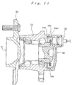
- Such roller bearing apparatuses are provided for example, as shown in Fig. 11 , with a roller bearing comprising an inner ring 51 as a rotary ring that co-rotates with a flange 50 to which a wheel is attached and an outer ring 52 that interposes multiple rolling elements between itself and the inner ring 51 and is attached to a vehicle body, and a closed-end cylindrical cover 54 attached to the outer ring 52 and carrying a rotation number detector 53 that detects the rotation number of a wheel.
- An end 54a of the cover 54 is fitted in the outer ring 52 against its inner periphery so as to close the opening of the outer ring 52 at one end.
- the cover is conventionally produced by pressing a metal plate.
- synthetic resin covers produced by injection molding using a metal mold have been recently proposed in place of metal covers in order to reduce the cost (for example, see Japanese Unexamined Patent Publication No. 2001-318105 ).
- the synthetic resin cover 54 and metal outer ring 52 have different thermal expansion coefficients. When the temperature of the roller bearing apparatus rises, a small clearance may occur between the outer ring 52 and the cover 54, deteriorating the seal.
- roller bearing apparatus described in Japanese Unexamined Patent Publication No. 2004-76753 still allows a small clearance between the inner periphery 52a and the outer periphery 54a1, making it desirable to improve the sealing between the inner periphery 52a and the outer periphery 54a1 in order to ensure durability.
- the cover is provided with a sensor mount having a seating face as a sensor-mounting reference level. Abutting the seating face, a sensor is mounted on the sensor mount, by which the sensor and an encoder that is attached to and co-rotates with the rotary ring are provided at a specific distance.
- some forms of the sensor mount may sink (deform) as a result of thermal contraction of the synthetic resin in the course of molding, and the seating face of the sensor mount of the prior art cover will not be accurately formed, requiring post processing in order to use the seating face as a sensor-mounting reference level.
- a tilted seating face resulting from such deformation must be, for example, flattened to a level seating face by means of cutting and the like.
- Known structures for mounting a sensor include a sensor insertion opening formed in the cover through which a sensor body is inserted.
- the sensor is provided with a flange and a cap nut is embedded in the cover, and the flange is fixed to the cover with a bolt with the use of the cap nut (for example, see Japanese Unexamined Patent Publication No. 2003-13982 or document US6127819 ).
- the end face of the cap nut and the cover surface are in one plane (so-called leveled), to which the sensor flange is abutted and bolted.
- the senor is fixed by a bolt at the flange, so that secure fixation of the sensor is performed as compared to a sensor having no flange.
- the cover is made of synthetic resin
- the cap nut is easily placed in the cover by insert resin molding, which allows the cover to be produced at reduced cost. Further, the cap nut to be embedded in the cover is easily immobilized therein.
- the sensor flange is abutted to the cover surface, so that the sensor is axially positioned with increased accuracy as compared to a sensor having no flange.
- the cover easily sinks or warps in the course of molding. Therefore, when the flange is abutted to the cover, the sensor may be tilted or axially dislocated by the warpage of the cover, problematically deteriorating the sensor gap accuracy.
- the present invention is made in view of the above circumstances and an object thereof is to provide a roller bearing apparatus that resolves the problems associated with a synthetic resin cover, a method of producing the roller bearing apparatus, and a cover that is attached to the roller bearing apparatus.
- An object of the present invention is to provide a roller bearing apparatus in which a cap nut is provided in a synthetic resin cover and the cap nut is used to fix the sensor to the flange for positioning the sensor with improved accuracy.
- roller bearing apparatus is a roller bearing apparatus according to the appended claims.
- the nut end face (the other axial end side end face) of a cap nut and the cover surface are not on one plane (not leveled), unlike the prior art.
- the nut end face of the cap nut is positioned on the other axial end side of the outer cover surface facing the sensor flange. Consequently, the flange of the sensor (sensor flange) is in contact with the nut end face of the cap nut, but substantially not in contact with the outer cover surface. Therefore, the sensor is less influenced by sinkage or warpage of the cover, preventing the sensor from tilting or dislocating.
- roller bearing apparatus Examples of a roller bearing apparatus , a method of producing the roller bearing apparatus, and the cover that is attached to the roller bearing apparatus are described hereafter with reference to the drawings.
- Fig.1 is an axial cross-sectional view showing the structure of a roller bearing apparatus (wheel bearing apparatus).
- a wheel bearing apparatus 1 is used to rotatably support a wheel of a vehicle such as a car.
- the wheel bearing apparatus 1 comprises a roller bearing 10 that supports a wheel of a vehicle to which the wheel bearing apparatus 1 is attached and a cover 20 that closes the roller bearing 10 at one end.
- the roller bearing 10 is a double-row angular ball bearing, comprising an outer ring 11 as a fixed ring, an inner ring 12 as a rotary ring, an encoder 13 attached to the inner ring 12, multiple balls 14 as rolling elements provided between the outer and inner rings 11 and 12, holder 15 holding each of the balls 14, and a seal 16 provided in the clearance between the outer and inner rings 11 and 12 for sealing off the bearing interior.
- the inner ring 12 constitutes an axle to which an un-shown wheel is attached.
- the inner ring 12 consists of an inner shaft 17 and an inner ring member 18.
- the inner shaft 17 is provided with a socket part 17a and a flange 17b for mounting a wheel at one end.
- Multiple hub bolts 17c are fixed to the flange 17b for fastening the wheel.
- the inner shaft 17 is provided with a first inner ring track 12a on the outer periphery and, at the other end, a small-diameter part 17d having a diameter smaller than the inner ring track 12a. Having an annular form, the inner ring member 18 is press fitted on the small-diameter part 17d.
- a second inner ring track 12b is formed on the outer periphery of the inner ring member 18.
- the inner ring member 18 is press fitted in with one end face abutting a step 17e that connects the outer periphery of the inner ring body 17 and the small-diameter part 17d.
- a caulked part 17f is formed by caulking the tip of the small-diameter part 17d while the inner ring member 18 is pushed in, by which the inner ring member 18 is co-rotatably fixed to the inner shaft 17 while applying preload to the bearing 10.
- the outer ring 11 is provided, on the inner periphery, with a first outer ring track 11a and a second outer ring track 11b corresponding to the first and second inner ring tracks 12a and 12b, respectively, to rotatably support the inner ring 12 via balls 14.
- the outer ring 11 is provided, on the outer periphery, with a mount 11c for attaching the outer ring 11 to a vehicle.
- the outer ring 11 is provided with a cylindrical opening 11d having a large-diameter surface 11d1 having a diameter larger than the second outer ring track 11b at the axial end opposite to the flange 17b.
- the encoder 13 consists of an annular magnetic ring 13a and an annular supporting member 13b to which the magnetic ring 13a is attached. With the supporting member 13b fitted on the inner ring member 18 at the end, the encoder 13 is co-rotatably attached to the inner ring 12.
- the supporting member 13b is formed by bending a metal plate into an overall annular shape having an approximately L-shaped cross-section.
- the magnetic ring 13a is bonded to the annular part 13b1 of the supporting member 13b, for example, using adhesive in a manner in which different magnetic poles are continuously arranged in the circumferential direction.
- the cover 20 is described in detail hereafter.
- the cover 20 is provided with a cover body 21 attached to the outer ring 11 and a rotation number detector 22 attached to the cover body 21 with the tip being close to the encoder 13.
- the cover body 21 is provided with a nearly cylinder form with a closed-end.
- the open end of the cover body 21 is inserted in the large-diameter part 11d1 of the opening 11d of the outer ring 11 to close the opening 11d.
- the cover body 21 is provided with at the open end an inscribing surface 21a that is a cylindrical surface having a diameter smaller than the outer periphery of the cover body 21 and inscribes the large-diameter surface 11d1, and a stepped surface 21b that connects the inscribing surface 21a to the outer periphery of the cover body 21 (protruding radially outward from the inscribing surface 21a along the circumference).
- the cover body 21 is axially positioned with the stepped surface 21b abutting the axial end face 11d2 of the opening 11d of the outer ring 11.
- the diameter of the inscribing surface 21a is determined so that the inscribing surface 21a inscribes the large-diameter surface 11d1 with an appropriate interference.
- the cover body 21 is provided, at the bottom, with a bore 21c that communicates the interior of the cover 21 with the exterior.
- the rotation number detector 22 is inserted and fixed in the bore 21c.
- the rotation number. detector 22 is provided with a cylindrical shape that fits the inner periphery of the bore 21c.
- a groove 22a is formed on the outer periphery of the rotation number detector 22 in the circumferential direction and a sealing ring 22b is fitted therein to provide the sealing between the bore 21c and the rotation number detector 22.
- the rotation number detector 22 is fixed with the tip 22c being in the vicinity of the encoder 13, thereby detecting magnetic field changes caused by the magnetic ring 13a of the encoder 13.
- the rotation speed detector 22 outputs signals indicating the detected magnetic field changes from a harness 22d to an un-shown controller. The controller can obtain the wheel rotation speed based on the signals.
- Fig.2 is an enlarged view of the insertion of the outer ring 11 and cover 20 shown in Fig.1 .
- the outer ring 11 is provided with a beveled part 11e on the axial end face 11d2at at the rim along the entire circumference.
- the beveled part 11e is formed by so-called C beveling to remove the edge of the axial end face 11d2.
- the beveling rate is approximately 0.5 to 1 mm.
- the beveled part 11e as described above is generally formed in cutting a metal material and the beveled part 11e of this embodiment is one of those generally formed. In Fig.2 , the beveled part 11e is shown in an exaggerated manner for explanation.
- An annular space K is formed by the beveled part 11e, inscribing surface 21a, and stepped surface 21b at the base of the stepped surface 21b.
- the annular space K is filled with sealant S to provide a seal between the outer ring 11 and the cover 20.
- the sealant used here can be Locktight 5910 (trade name) of Henkel. Locktight 5910 (trade name) is a room temperature curing paste sealant.
- the sealant S joins and seals them tightly with an appropriate adhesion force so that they can be separated.
- the sealant S cures with an appropriate elastic property. Therefore, when a clearance occurs between the inscribing surface 21a and the large-diameter surface 11d1 as a result of difference in thermal expansion coefficient between the outer ring 11 and the cover 20, the elasticity of the sealant S allows for clearance and maintains the sealed state.
- the sealant S is filled in the annular space K and interposed between the outer ring 11 and the cover 20, by which the cover 20 can close the opening 11d of the ring 11 in a sealed state, preventing muddy water and the like from entering the interior of the vehicle bearing apparatus 1, thus ensuring its durability and preventing the detection accuracy of the rotation number detector 22 from deteriorating.
- the beveled part 11e is formed in the prior art and there is no need of additional process such as grooving, as required in the prior art embodiment described above. Therefore, the sealing between the cover 20 and the outer ring 11 can be accomplished without a significant increase in cost.
- the beveled part 11e can be formed at a larger beveling rate or the beveled part 11e can be an R-bevel as shown in Fig.3a or a recessed R-bevel as shown in Fig.3b .
- the sealant S connects the beveled part 11e, inscribing surface 21a, and stepped surface 21b with an appropriate adhesive force so that they can be separated. Therefore, the cover 20 can be easily removed from the roller bearing 10, for example, on disassembly for maintenance.
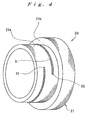
- Fig.4 is a perspective view of the cover 20 before it is inserted in the outer ring 11.
- the sealant S is applied to the inscribing surface 21a nearly in the center in the axial direction in the form of a circumferential ridged streak having two ends.
- the sealant S applied in the form of a ridged streak having two ends runs along the entire circumference of the inscribing surface 21a and the ends S1 and S2 overlap seen in the axial direction.
- the cover 20 is inserted in the large-diameter surface 11d1 of the outer ring 11.
- the method of producing the vehicle bearing apparatus of the example described above has the following effects when the cover 20 is attached to the outer ring 11. Most of the sealant S applied in a ridge form is pushed by the axial end face 11d2 of the outer ring 11 (the beveled part 11e) and shifted toward the base end of the stepped surface 21b. When the axial end face 11d2 abuts the stepped surface 21b, most of the sealant S is filled in the annular space K.
- the sealant S is shifted to the base end of the stepped surface 21b, a small amount of the sealant S is extended over the large-diameter surface 11d1 and, therefore, the sealant S is interposed between the large-diameter surface 11d1 and the inscribing surface 21a. In this way, the sealant S interposed over an extended area ensures a seal between the outer ring 11 and the cover 20.
- the sealant S can be applied to the inscribing surface 21a in an amount more than necessary to fill the annular space K with no problems. However, it is preferable that the sealant S be applied in an amount necessary and sufficient to fill the annular space K. This is because the sealing between the outer ring 11 and cover 20 is provided as long as the annular space K is filled with the sealant S and any more sealant S is redundant.
- the sealant S is applied in a ridged streak.
- it can be applied to the inscribing surface 21 a in a flat form.
- the inscribing surface 21a is provided with an appropriate interference relative to the large-diameter surface 11d1 and the clearance between the inscribing surface 21a and the large-diameter surface 11d1 is very small. Even if the sealant S is applied in a flat form, the axial end face 11d2 sweeps and pushes the sealant S toward the base of the stepped surface 21b.
- Fig.5 is an axial cross-sectional view of a roller bearing apparatus to which the cover according to the second aspect of the present invention is attached.
- the inner side of a vehicle is to the right and the outer side (wheel side) of the vehicle is to the left.
- a sensor-equipped roller bearing apparatus 101 comprises a roller bearing unit 102 and a sensor unit 103.
- the roller bearing unit 102 is of a double-row angular ball bearing type, comprising an outer ring 104, an inner shaft (hub wheel) 105 and an inner ring member 106 as an inner ring, and rolling elements 107 and 108 consisting of multiple balls.
- the roller bearing unit 102 has holders 109 and 110 that hold the rolling elements 107 and 108, respectively, at specific intervals in the circumferential direction and a seal member 111 provided in a clearance between the outer ring 104 and the inner shaft 105. Further, the roller bearing unit 102 is provided with a cover 112 of the present invention to close off the bearing interior on the vehicle inner side of the outer ring 104. The cover 112 seals the annular opening between the inner and outer rings from the vehicle inner side and, together with the seal member 111 that seals the annular opening from the vehicle outer side, prevents muddy water and foreign substances from entering the bearing interior.
- the outer ring 104 is a fixed ring that is fastened to the vehicle and has multiple rows of outer ring tracks 104a and 104b on the inner periphery.
- the rotary ring consists of the inner shaft 105 and inner ring member 106.
- the inner shaft 105 is provided with an inner ring track 105a in a position corresponding to the outer ring track 104a, where the rolling element 107 rotates between the inner and outer ring tracks 105a and 104a.
- the inner ring member 106 is provided with an inner ring track 106a in a position corresponding to the outer ring track 104b, where the rolling element 108 rotates between the inner and outer ring tracks 106a and 104b.
- the inner shaft 105 is provided with a socket part 105b and a flange 105c for mounting a wheel on the vehicle outer side. Multiple hub bolts 120 are pressed in the flange 105c to fasten a wheel.
- the inner shaft 105 is provided with a step 105d on the vehicle inner side.
- the inner ring member 106 is fitted on the step 105d.
- the inner ring member 106 is fixed to the inner shaft 105 by a caulked part 105e formed by bending the tip of the step 105d radially outward.
- the sensor unit 103 includes, for example, a polarized pulsar ring 132 and a sensor 133 facing the ring 132.
- the rotation speed of the wheel is detected by detecting the rotation number of the roller bearing unit 102.
- the polarized pulsar ring 132 is co-rotatable with the inner ring member 106.
- the polarized pulsar ring 132 constitutes a target (an object to be detected) of the sensor 133.
- Multiple N and S magnetic poles are alternately provided on the circumference of the ring 132.
- the sensor 133 is installed in the roller bearing unit 102 by means of the cover 112 that is provided with a sensor-mounting function in addition to the inherent function of closing off the bearing interior.
- the sensor 133 is provided with a sensor body 133a containing a magnetic detection element such as a hall element, and a supporting member 133b on which the sensor body 133a is integrally mounted for supporting the sensor body 133a.
- the sensor body 133a and supporting member 133b are mounted on the sensor mount 112b of the cover 122, by which the magnetic detection surface of the sensor body 133a faces the N and S magnetic poles of the polarized pulsar ring 132 at a specific distance.
- the sensor body 133a detects magnetic field changes caused by the polarized pulsar ring 132 corresponding to the bearing rotation and outputs detection signals to an un-shown controller such as an ECU, by which the rotation number of the roller bearing unit 102 and the wheel rotation speed are detected.
- an un-shown controller such as an ECU
- a sensor unit having a sensor body of different sensing system such as electric capacitance system and a corresponding target can be used to detect the rotation number and rotation speed and, additionally, the wheel rotation direction.
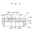
- the cover 112 is made of a synthetic resin such as nylon 66 mixed with glass fibers and formed as one piece by injection molding using a metal mold. As also shown in Figs. 6 to 8 , the cover 112 comprises a partition 112a that partitions the interior of the roller bearing unit 102 from the exterior and a sensor mount 112b having a seating face 112b1 that constitutes a reference level for mounting the sensor 133 ( Fig.5 ) on the axially outer end face 112a1 of the partition 112a.
- a synthetic resin such as nylon 66 mixed with glass fibers
- the cover 112 is provided with a cylindrical part 112c extended axially outward from the axially outer end face 112a1 of the partition 112a and multiple, for example, four, ribs 112d1, 112d2, 112d3, and 112d4 formed on the end face 112a1.
- the ribs 112d1 to 112d4, sensor-mount 112b, and cylindrical part 112c constitute specific recesses 113a and 113b.
- the partition 112a is a thin nearly circular member that substantially closes off the bearing interior.
- the partition 112a is provided with a circumferentially continued step that is extended axially inward from the axially inner end face 112a2 and ends with an outer periphery 112e and an annular end face 112f.
- the outer periphery 112e of the cover 112 is pressed in the outer ring 104 against inner periphery 104c ( Fig.5 ), by which the cover 112 is attached to the roller bearing unit 102 in the manner that the outer periphery 112e and inner periphery 104c is pressed against each other and the annular end face 112f is pressed against the axial end face 104d of the outer ring 104 ( Fig.5 ), thereby the partition 112a faces and closes off the bearing interior.
- the inner periphery 104c of the outer ring 104 is provided with a flange on the outer side of the outer periphery.
- the sensor mount 112b is provided with a rectangular parallel-piped shape continued from the axially outer end face 112a1 of the partition 112a.
- the sensor mount 112b is provided with a flat seating face 112b1 constituted by the axially outer surface of the mount 112b itself, a through-hole 112b2 of which one and the other openings are formed in the seating face 112b1 and in the axially inner end face 112a2 of the partition 112a, respectively, and through which the sensor body 133a ( Fig.5 ) is inserted, and a placing hole 112b3 that opens to the seating face 112b1 and in which a nut 135 is placed.
- the nut 135 is previously introduced in the placing hole 112b3 and buried therein by insert molding in the course of producing the cover 112 by molding.
- a bolt 134 ( Fig.5 ) is threaded in the nut 135 with the surface of the supporting member 133b ( Fig.5 ) abutting the seating face 112b1, by which the sensor 133 ( Fig.5 ) is mounted on the cover 112 with the magnetic detection surface of the sensor body 133a introduced in the through-hole 112b2 being at a specific distance from the encoder 132 ( Fig.5 ).
- the sensor body 133a is air-tightly introduced in the through-hole 112b2, thereby preventing the sealing property of the partition 112a and, in turn, the cover 112 from deteriorating.
- the ribs 112d1 to 112d4 have a thin plate form continued from the axially outer end face 112a1 of the partition 112a.
- the ribs 112d1 to 112d4 integrate the sensor mount 112b and cylindrical part 112c on the end face 112a1.
- the ribs 112d1 to 112d4 are connected to the inner periphery of the cylindrical part 112c at one end.
- the ribs 112d1 to 112d3 are connected to the sensor mount 112b via a nearly semi-circular rib connection part 112d5 formed continuously from the end face 112a1 at the other end.
- the other end of the rib 112d4 having a smaller length in the radial direction than the ribs 112d1 to 112d3 is directly connected to the senor mount 112b.
- the ribs 112d1 to 112d3 and the rib 112d4 connected to the sensor mount 112b are arranged at intervals of 90° around the axis.
- the recesses 113a having a fan-shape are formed on the end face 112a1 by the cylindrical part 112c, rib 112d, rib 112d2, and rib connection part 112d5 and by the cylindrical part 112c, rib 112d2, rib 112d3, and rib connection part 112d5.
- the recesses 113b having a nearly fan-shape are formed on the end face 112a1 by the cylindrical part 112c, rib 112d1, rib 112d4, and sensor mount 112b and by the cylindrical part 112c, rib 112d3, rib 112d4, and sensor mount 112b.
- Recesses 112g and 112h provided on the axially outer surface of the rib connection part 112d5 and the axially inner end face 112a2 of the partition 112a, respectively, result from positioning projections provided in the metal mold, which help to form the parts of the cover 112 with accuracy using the metal mold.
- the ribs 112d1 to 112d4 and rib connection part 112d5 are provided to form the recesses 113a and 113b on the axially outer end face 112a1 of the partition 112a where the sensor mount 112b having the seating face 112b1 is provided, leading to a reduction in the amount of synthetic resin on the end face 112a1 on which the seating face 112b1 is formed. This consequently prevents the seating face 112b1 of the sensor mount 112b from being deformed due to thermal contraction of the synthetic resin in the course of producing the cover 112 by molding.
- a highly accurate seating face 112b1 can be easily formed without any post-processing such as cutting.
- the seating face 112b1 that constitutes a reference level for mounting the sensor 133 can be formed with high accuracy, preventing the assembly accuracy of the polarized pulsar ring 132 and sensor body 133a from deteriorating and, therefore, preventing the sensor detection results from deteriorating due to the deteriorated assembly accuracy.
- the lack of need for post-processing prevents unnecessary increase in cost to produce a lightweight cover 112.
- the seating face of the sensor mount, ribs, and recesses are formed on the axially outer end face of the partition.
- the example above is not restricted in the number and shape of the ribs and recesses as long as the seating face that constitutes a sensor mounting reference level is formed on one of the inner and outer end faces of the partition that partitions the interior of the roller bearing apparatus from the exterior and the ribs are provided on one end face to form the specific recesses on one end face together with the sensor mount.
- the ribs 112d1 to 112d3 can be directly connected to the sensor mount 112b.
- the end face of the partition within the inner periphery of the cylindrical part is divided into three regions by three ribs and the sensor mount can be provided in one of the three recesses as a separate piece from the ribs.
- the sensor mount integrated with a rib is preferable in terms of forming a highly accurate seating face without complicating the mold shape. This is also preferable in terms of reinforcing the sensor mount by the ribs and maintaining its shape.
- the sensor mount 112b and ribs 112d1 to 112d4 provided continuously to the end face 112a1 are arranged within the inner periphery of the cylindrical part 112c.
- the ribs can be provided above the end face 112a1 at a distance in which one end and the other end in the radial direction are connected to the sensor mount 112b and the cylindrical part 112c, respectively.
- the recesses 113a and 113b can be open at the outer periphery.
- providing the cylindrical part described above is preferable in terms of effectively preventing the ribs and sensor mount from being deformed. This is also preferable in terms of forming a cover that is easy to handle, facilitating mounting to the bearing apparatus.
- the example is applied to a vehicle driven wheel hub unit provided with a double-row angular ball bearing.
- bearing systems including the type and number of rolling elements are not restricted in any way.
- the example can be applied to a roller bearing apparatus constituting a vehicle driving wheel hub unit comprising a conical roller and having the interior of the bearing apparatus closed by a cover from vehicle outer side.
- the example can also be applied to a variety of roller bearing apparatuses that are installed in machines such as a rotary machine and equipment other than hub units.
- roller bearing apparatus according to the present invention is described hereafter.
- Fig.9 is a cross-sectional view of a roller bearing apparatus 201 according to the present invention.
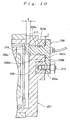
- Fig.10 is an enlarged view of the main part in Fig.9 .
- a sensor 208 and a bolt 214 for mounting the sensor 208 are provided in a roller bearing apparatus 201.
- the roller bearing apparatus 201 comprises an outer ring 202, an inner ring member 204 provided on the inner periphery side of the outer ring 202 via balls 203 as rolling elements, and an inner shaft 206 having the inner ring member 204 attached on the outer periphery and a flange 205 to which a wheel is attached at one axial end.
- the outer ring 202 has two outer ring tracks 202a and an outer ring flange 202b by which the outer ring 202 is attached to a vehicle body.
- the inner ring 204 is fitted on a small-diameter part 206a provided at the other axial end of the inner shaft 206.
- the inner ring 204 is fixed by a caulked part 210 formed by plastically deforming the other axial end of the inner shaft 206 while being pushed toward the one axial end.
- Two inner ring tracks facing the two outer ring tracks 202a consists of a first inner ring track 206b formed by the outer periphery of the inner shaft 206 and a second inner ring track 204a formed by the outer periphery of the inner ring 204.
- the outer ring 202 having multiple rows of outer ring tracks 202a, inner ring member 204 having the second inner ring track 204a, inner shaft 206 having the first inner ring track 206b, multiple rows of balls 203 interposed between these track surfaces constitute a multiple-row angular ball bearing 211.
- the flange 205 is provided with a bolt-hole 205a for inserting a bolt 213.
- An un-shown wheel is fastened to the flange 205 by the bolt 213 inserted in the bolt-hole 205a.
- Crown-shaped holders 212 maintain the balls 203 in each row at nearly equal intervals in the circumferential direction.
- a synthetic resin cover 207 is provided at the other axial end of the outer ring 202.
- the cover 207 is attached to close the opening at the other axial end of the outer ring 202, thereby preventing foreign substances from entering the bearing 211.
- the cover 207 is provided with a sensor insertion opening 207a for inserting the sensor body 208a of a sensor 208 and a cap nut 209 for fixing the sensor 208 by a bolt 214.
- a pulsar ring 215 as a member for detecting the rotation is provided on the inner ring 204 that co-rotates with an un-shown wheel.
- the pulsar ring 215 is made by attaching magnetic rubber to an annular carbon steel plate, having N and S poles alternately arranged in the circumferential direction.
- the sensor 208 mounted on the roller bearing apparatus 201 is provided with an axially cylindrical sensor body 208a and a sensor flange 208b radially extended at the other axial end of the sensor body 208a.
- a rotation detection element 208c (shown by the dotted lines in Fig. 10 ) is embedded in the sensor body 208a at the tip (one axial end). In the vicinity of the pulsar ring 215, the element 208c detects the rotation number of the inner shaft 206 or an un-shown wheel.
- the rotation number detection system is not restricted to this embodiment and various systems used with a rotary encoder including a photoelectric system can be used.
- the cover 207 is formed by injection molding a thermoplastic resin such as reinforced polyamide resin.
- the cap nut 209 is pre-placed in a metal mold and, then, the resin is poured in the metal mold to embed the cap nut in the cover 207.
- the cap nut 209 is immobilized with the axial direction of the nut hole being in parallel with that of the bearing apparatus 201.
- the nut end face 209a is in a plane radially parallel with the other axial end side surface of the cover 207 (including the cover outer surface 207b, described later).
- the nut end face (the other axial end side face) 209a of the cap nut 209 is exposed on the other axial end side of the cover 207.
- the cap nut 209 is embedded in the cover 207, protruding on the other axial end side by an axial distance d. Consequently, the nut end face 209a is on the other axis end side of the cover outer surface 207b facing the inner flange surface 208b1 of the sensor flange 208b. Therefore, when the sensor flange 208b of the sensor 208 is fastened by the bolt 214 and cap nut 209, the inner flange surface 208b1 of the sensor flange 208b is in area contact with the nut end face 209a, but not in contact with the cover outer surface 207b. With the bolt being fastened, the sensor 208 is positioned by the nut end face 209a, receiving no influence from the cover outer surface 207b.
- the cover outer surface 207b of the cover 207 When the cover outer surface 207b of the cover 207 is subject to deformation such as warpage or sinkage, the cover outer surface 207b and inner flange surface 208b1 may partially contact each other (hereafter also termed “partial contact”), and the sensor 208 is dominantly positioned by the nut end face 209a, because the nut end face 209a and inner flange surface 208b1 are in are contact with each other with relatively high contact pressure while the cover outer surface 207b and inner flange surface 208b1 are in partial contact with relatively low contact pressure. Therefore, the sensor 208 is less influenced by warpage or sinkage of the cover 207, preventing the sensor 208 from tilting or dislocating.
- the axial distance d between the cover outer surface 207b and the inner flange surface 208b1 is preferably 10 to 100 ⁇ m and more preferably 20 to 30 ⁇ m.
- the axial distance d is excessively large, an unnecessarily large space is required.
- the axial distance d is excessively small, partial contact between the cover outer surface 207b and inner flange surface 208b1 as described above may become more influential.
- An O ring 217 is provided between the outer periphery of the sensor body 208a and the inner periphery of the sensor insertion opening 207a. Therefore, there is no increase in foreign substances entering the interior of the roller bearing apparatus 201 through the sensor insertion opening 207a because of the axial distance d.
- the cover 207 is formed by pre-placing the cap nut 209 in a metal mold and pouring a synthetic resin in the metal mold. In the molding process, some part of the cap nut 209 should abut the metal mold to immobilize it at a specific position in the metal mold before the synthetic resin is poured in.
- the cap nut 209 is covered with the synthetic resin except for the nut end face 209a (and a small part of the periphery adjacent to the nut end face 209a). Consequently, the part of the cap nut 209 that abuts the metal mold is the nut end face 209a. Even if the cover 207 suffers from warpage or sinkage after the molding, the nut end face 209a is not dislocated within the metal mold. Therefore, the nut end face 209a is positioned with higher accuracy than the cover outer surface 207b.
- the present invention improves the accuracy of positioning the sensor 208 and decreases errors in the sensor gap g, thereby improving the rotation detection accuracy of the sensor 208.
Landscapes
- Engineering & Computer Science (AREA)
- Mechanical Engineering (AREA)
- General Engineering & Computer Science (AREA)
- Physics & Mathematics (AREA)
- General Physics & Mathematics (AREA)
- Rolling Contact Bearings (AREA)
- Sealing Of Bearings (AREA)
- Rolls And Other Rotary Bodies (AREA)
Claims (7)
- Appareil formant palier à rouleaux, comprenant:- un anneau extérieur (202);- un élément en anneau intérieur (204) prévu sur un côté de la périphérie intérieure de l'anneau extérieur (202) via des éléments de roulement (203);- un arbre intérieur (206) ayant l'élément en anneau intérieur (204) attaché sur la périphérie extérieure et une bride (205) pour monter une roue à une extrémité axiale;- un élément de détection (215) prévu sur l'élément en anneau intérieur (204) ou sur l'arbre intérieur (206), qui est en rotation conjointement avec la roue, pour détecter une rotation;- un couvercle en résine synthétique (207) attaché à l'anneau extérieur (202) à l'autre extrémité axiale ;- une ouverture d'insertion de capteur (207a) prévue à travers le couvercle (207) dans la direction axiale; et- un écrou-capuchon (209) noyé dans le couvercle (207) avec une face terminale d'écrou (209a) exposée pour fixer une bride de capteur (208b) d'un capteur (208) sur le couvercle (207) sur le côté de l'autre extrémité axiale,caractérisé en ce que
l'écrou-capuchon (209) est noyé dans le couvercle (207) d'une manière telle que la face terminale d'écrou (209a) de l'écrou-capuchon (209) se projette depuis la surface extérieure (207b) du couvercle sur le côté de l'autre extrémité axiale sur une distance axiale (d),
dans lequel la face terminale d'écrou (209a) est positionnée sur le côté de l'autre extrémité axiale de la surface extérieure (207b) du couvercle en face de la surface de bride intérieure (208bà) de la bride de capteur (208b), dans lequel le capteur (208) est destiné à être inséré dans l'ouverture d'insertion de capteur (207a) du couvercle (207), de sorte que la surface de bride intérieure (208b1) de la bride de capteur (208b) est en contact avec la face terminale d'écrou (209a), mais n'est pas en contact avec la surface extérieure (207b) du couvercle quand la bride de capteur (208b) est fixée sur le couvercle (207) par l'écrou-capuchon (209) et un boulon (214). - Appareil selon la revendication 1,
dans lequel la distance (d) est dans une plage de 10 µm à 100 µm, en particulier de 20 µm à 30 µm. - Appareil selon la revendication 1 ou 2,
dans lequel un élément de détection de rotation (208c) est noyé dans un corps de capteur (208a) de l'élément de détection (208) et est positionné, en direction axiale, à l'opposé d'un anneau de pulseur (215) monté sur l'élément d'anneau intérieur (204). - Appareil selon la revendication 3,
dans lequel le corps de capteur (208a) est espacé de l'anneau de pulseur (215) à raison d'un intervalle de capteur (g). - Appareil selon l'une quelconque des revendications 1 à 4,
dans lequel le couvercle (207) est réalisé en résine thermoplastique moulée ayant l'écrou-capuchon (209) noyé et immobilisé à l'intérieur. - Appareil selon l'une quelconque des revendications 1 à 5,
dans lequel un joint torique (217) est prévu entre la périphérie extérieure du corps de capteur (208a) de l'élément de détection (208) et la périphérie intérieure de l'ouverture d'insertion de capteur (207a). - Appareil selon l'une quelconque des revendications 1 à 6,
dans lequel la face terminale d'écrou (209a) est dans un plan parallèle à une direction radiale, et la surface extérieure (207b) du couvercle est sur le côté de l'autre extrémité axiale.
Applications Claiming Priority (4)
| Application Number | Priority Date | Filing Date | Title |
|---|---|---|---|
| JP2005043850A JP2006226491A (ja) | 2005-02-21 | 2005-02-21 | 転がり軸受装置及びその製造方法 |
| JP2005097252A JP2006275200A (ja) | 2005-03-30 | 2005-03-30 | 転がり軸受装置のカバー及びこれを用いた転がり軸受装置 |
| JP2005097313A JP4457940B2 (ja) | 2005-03-30 | 2005-03-30 | 転がり軸受装置 |
| EP06003430.3A EP1693676B1 (fr) | 2005-02-21 | 2006-02-20 | Roulement et méthode pour sa fabrication |
Related Parent Applications (2)
| Application Number | Title | Priority Date | Filing Date |
|---|---|---|---|
| EP06003430.3 Division | 2006-02-20 | ||
| EP06003430.3A Division EP1693676B1 (fr) | 2005-02-21 | 2006-02-20 | Roulement et méthode pour sa fabrication |
Publications (3)
| Publication Number | Publication Date |
|---|---|
| EP2251699A2 EP2251699A2 (fr) | 2010-11-17 |
| EP2251699A3 EP2251699A3 (fr) | 2011-01-12 |
| EP2251699B1 true EP2251699B1 (fr) | 2016-05-04 |
Family
ID=36061366
Family Applications (2)
| Application Number | Title | Priority Date | Filing Date |
|---|---|---|---|
| EP10174787.1A Expired - Lifetime EP2251699B1 (fr) | 2005-02-21 | 2006-02-20 | Roulement, méthode pour sa fabrication et le couvercle associé. |
| EP06003430.3A Expired - Lifetime EP1693676B1 (fr) | 2005-02-21 | 2006-02-20 | Roulement et méthode pour sa fabrication |
Family Applications After (1)
| Application Number | Title | Priority Date | Filing Date |
|---|---|---|---|
| EP06003430.3A Expired - Lifetime EP1693676B1 (fr) | 2005-02-21 | 2006-02-20 | Roulement et méthode pour sa fabrication |
Country Status (3)
| Country | Link |
|---|---|
| US (1) | US7556435B2 (fr) |
| EP (2) | EP2251699B1 (fr) |
| CA (1) | CA2536190A1 (fr) |
Families Citing this family (22)
| Publication number | Priority date | Publication date | Assignee | Title |
|---|---|---|---|---|
| WO2006030669A1 (fr) * | 2004-09-15 | 2006-03-23 | Ntn Corporation | Dispositif de roulement à capteur rotatif |
| JP4695929B2 (ja) * | 2005-06-30 | 2011-06-08 | 日立オートモティブシステムズ株式会社 | 非接触式の回転角度検出装置とその製造方法及びそれを用いたスロットル弁制御装置 |
| JP4907459B2 (ja) * | 2007-08-01 | 2012-03-28 | 株式会社ジェイテクト | 車両用軸受装置 |
| DE102008006605B4 (de) * | 2008-01-30 | 2014-11-20 | Ford Global Technologies, Llc | Lagerkappe |
| EP2112002A3 (fr) * | 2008-03-28 | 2009-12-09 | JTEKT Corporation | Ensemble de roulement de roue et son procédé de fabrication |
| JP5331640B2 (ja) * | 2009-10-05 | 2013-10-30 | Ntn株式会社 | 回転速度検出装置付き車輪用軸受装置 |
| ITTO20120364A1 (it) * | 2012-04-24 | 2013-10-25 | Skf Ab | Coperchio porta-sensore per un cuscinetto di un mozzo-ruota |
| DE102012208592A1 (de) * | 2012-05-23 | 2013-11-28 | Schaeffler Technologies AG & Co. KG | Radlagerkappe und Radlager |
| ITTO20130005A1 (it) * | 2013-01-08 | 2014-07-09 | Skf Ab | Gruppo cuscinetto per una ruota di un veicolo |
| FR3001538B1 (fr) * | 2013-01-31 | 2016-03-11 | Ntn Snr Roulements | Ensemble instrumente pour systeme tournant. |
| DE102014200274B4 (de) | 2014-01-10 | 2025-05-28 | Ford Global Technologies, Llc | Lagerkappe |
| DE102014200273B4 (de) | 2014-01-10 | 2018-04-19 | Ford Global Technologies, Llc | Lagerkappe |
| DE202014100116U1 (de) | 2014-01-10 | 2014-02-17 | Ford Global Technologies, Llc | Lagerkappe |
| DE102014206764A1 (de) * | 2014-04-08 | 2015-10-29 | Schaeffler Technologies AG & Co. KG | Radlagereinheit |
| DE102014208422B4 (de) | 2014-05-06 | 2018-03-01 | Schaeffler Technologies AG & Co. KG | Radlagereinheit |
| EP2995471A1 (fr) | 2014-08-26 | 2016-03-16 | Aktiebolaget SKF | Roulement, en particulier ensemble de roulement et moyeu de roue, avec un codeur et un capuchon d'étanchéité pourvu d'un support de capteur |
| CN107795341A (zh) * | 2017-12-06 | 2018-03-13 | 中国船舶重工集团公司第七0三研究所 | 一种汽轮机轴承箱端盖结构 |
| JP7106947B2 (ja) | 2018-04-03 | 2022-07-27 | 株式会社デンソー | 位置検出装置 |
| IT201900000250A1 (it) * | 2019-01-09 | 2020-07-09 | Skf Ab | Gruppo mozzo-ruota per veicoli |
| IT201900023355A1 (it) * | 2019-12-09 | 2021-06-09 | Skf Ab | Gruppo sospensione sensorizzato per veicoli, includente una unità mozzo ruota ed un montante o articolazione di sospensione, metodo e unità mozzo ruota associati |
| DE102020103421A1 (de) * | 2020-02-11 | 2021-08-12 | Liebherr-Components Biberach Gmbh | Wälzlager mit Überwachungsvorrichtung |
| JP7652662B2 (ja) * | 2021-08-20 | 2025-03-27 | Ntn株式会社 | センサホルダおよび車輪用軸受装置 |
Family Cites Families (23)
| Publication number | Priority date | Publication date | Assignee | Title |
|---|---|---|---|---|
| US2751806A (en) * | 1953-10-12 | 1956-06-26 | Hi Shear Rivet Tool Company | Fastener provided with circumferential fluid sealing ring bonded in recess |
| GB1362797A (en) * | 1970-11-28 | 1974-08-07 | Lucas Industries Ltd | Bearings for gear pumps |
| US4498709A (en) * | 1983-06-30 | 1985-02-12 | Rockwell International Corporation | Axle for use with a tire inflation system |
| JPH0747984B2 (ja) * | 1985-03-27 | 1995-05-24 | 本田技研工業株式会社 | 動力伝達装置のカバー構造 |
| JP2513584Y2 (ja) * | 1990-04-09 | 1996-10-09 | 日本精工株式会社 | 回転速度検出用ハブユニット |
| US5296805A (en) * | 1992-08-17 | 1994-03-22 | General Motors Corporation | Serviceable wheel speed sensor with magnet assisted retention |
| GB9218150D0 (en) * | 1992-08-26 | 1992-10-14 | Pilkington Glass Ltd | Insulating units |
| JPH07243448A (ja) * | 1994-03-01 | 1995-09-19 | Toi Kenma Kogyo Kk | 旋回ころがり軸受 |
| EP0751311B1 (fr) * | 1995-03-16 | 2005-02-16 | Nsk Ltd | Palier à roulement avec capteur de vitesse de rotation |
| IT235863Y1 (it) * | 1995-05-19 | 2000-07-18 | Skf Ind Spa | Dispositivo di rilevamento della velocita' di rotazione con sensorestaccabile. |
| US5814984A (en) * | 1995-08-22 | 1998-09-29 | Nsk Ltd. | Roller bearing unit having an improved structure for retaining and sealing a cover thereon |
| JP3687160B2 (ja) * | 1995-12-13 | 2005-08-24 | 日本精工株式会社 | 回転速度検出装置付転がり軸受ユニット |
| DE69815739T2 (de) * | 1997-03-31 | 2004-04-22 | Nsk Ltd. | Kugellager mit Drehzahlsensor |
| GB2330417B (en) * | 1997-10-17 | 1999-09-08 | Nsk Ltd | Rolling bearing unit with rotational speed sensor |
| JPH11118817A (ja) * | 1997-10-20 | 1999-04-30 | Nippon Seiko Kk | 回転速度検出装置付転がり軸受ユニット |
| US6079966A (en) * | 1997-11-18 | 2000-06-27 | Zexel Usa Corporation | Compressor housing |
| JP2971870B1 (ja) * | 1998-09-29 | 1999-11-08 | 川崎重工業株式会社 | ベルトコンバータのカバー構造 |
| US6315300B1 (en) * | 1998-11-24 | 2001-11-13 | Hi-Shear Corporation | Solid sealant with environmentally preferable corrosion resistance |
| JP2001318105A (ja) | 2000-05-09 | 2001-11-16 | Nsk Ltd | 回転速度検出用転がり軸受ユニット |
| JP2003013982A (ja) | 2001-06-29 | 2003-01-15 | Nsk Ltd | エンコーダ付軸受ユニット |
| US20030110718A1 (en) * | 2001-12-17 | 2003-06-19 | Daniel Boisvert | Marine window assembly |
| JP3988576B2 (ja) | 2002-08-09 | 2007-10-10 | 株式会社ジェイテクト | 転がり軸受装置 |
| WO2006049126A1 (fr) * | 2004-11-01 | 2006-05-11 | Jtekt Corporation | Capot avec capteur de dispositif de roulement pour roue |
-
2006
- 2006-02-13 CA CA002536190A patent/CA2536190A1/fr not_active Abandoned
- 2006-02-15 US US11/354,244 patent/US7556435B2/en active Active
- 2006-02-20 EP EP10174787.1A patent/EP2251699B1/fr not_active Expired - Lifetime
- 2006-02-20 EP EP06003430.3A patent/EP1693676B1/fr not_active Expired - Lifetime
Also Published As
| Publication number | Publication date |
|---|---|
| US20060228062A1 (en) | 2006-10-12 |
| EP2251699A3 (fr) | 2011-01-12 |
| EP1693676A3 (fr) | 2006-12-06 |
| CA2536190A1 (fr) | 2006-08-21 |
| EP1693676B1 (fr) | 2013-05-01 |
| EP2251699A2 (fr) | 2010-11-17 |
| US7556435B2 (en) | 2009-07-07 |
| EP1693676A2 (fr) | 2006-08-23 |
Similar Documents
| Publication | Publication Date | Title |
|---|---|---|
| EP2251699A2 (fr) | Roulement, méthode pour sa fabrication et le couvercle associé. | |
| EP1041387B1 (fr) | Combinaison de joint annulaire avec codeur | |
| CN102666127A (zh) | 结合有转速检测装置的车轮轴承装置 | |
| KR101391576B1 (ko) | 센서를 구비한 휠 베어링 | |
| US5438260A (en) | Removable device for sensing the rotation speed of a bearing, and a vehicle wheel hub assembly equipped with same | |
| US20090058403A1 (en) | Magnetic encoder | |
| US7632020B2 (en) | Sealing arrangement | |
| JP2014013073A (ja) | 車輪用軸受装置 | |
| US8636418B2 (en) | Wheel bearing arrangement with sensor stop | |
| JP2008265361A (ja) | 車輪用軸受装置 | |
| US7534046B2 (en) | Wheel support bearing assembly | |
| EP0401464B1 (fr) | Dispositif palier pour un arbre en rotation dans un véhicule | |
| JP3636201B1 (ja) | 回転速度検出装置付転がり軸受ユニット | |
| JP2008175382A (ja) | 回転速度検出装置付車輪支持用転がり軸受ユニット | |
| JP2003013982A (ja) | エンコーダ付軸受ユニット | |
| US11458764B2 (en) | Wheel bearing having improved sensor target and sensor target mounting portion | |
| CN116906455A (zh) | 设置有传感器的带凸缘车轮轮毂轴承 | |
| JP2009150421A (ja) | 回転速度検出装置付車輪用軸受装置 | |
| JP2008256079A (ja) | センサ付き車輪支持用軸受ユニット | |
| JP2006275200A (ja) | 転がり軸受装置のカバー及びこれを用いた転がり軸受装置 | |
| US6679633B2 (en) | Assembly forming a roller bearing equipped with an information sensor device | |
| JP4457940B2 (ja) | 転がり軸受装置 | |
| JP4045821B2 (ja) | 転がり軸受装置におけるシール部材の取付け方法 | |
| JP2006226491A (ja) | 転がり軸受装置及びその製造方法 | |
| JP3306918B2 (ja) | 車輪の回転速度検出装置 |
Legal Events
| Date | Code | Title | Description |
|---|---|---|---|
| PUAI | Public reference made under article 153(3) epc to a published international application that has entered the european phase |
Free format text: ORIGINAL CODE: 0009012 |
|
| AC | Divisional application: reference to earlier application |
Ref document number: 1693676 Country of ref document: EP Kind code of ref document: P |
|
| AK | Designated contracting states |
Kind code of ref document: A2 Designated state(s): DE FR GB |
|
| PUAL | Search report despatched |
Free format text: ORIGINAL CODE: 0009013 |
|
| AK | Designated contracting states |
Kind code of ref document: A3 Designated state(s): DE FR GB |
|
| 17P | Request for examination filed |
Effective date: 20110712 |
|
| 17Q | First examination report despatched |
Effective date: 20121120 |
|
| REG | Reference to a national code |
Ref country code: DE Ref legal event code: R079 Ref document number: 602006049021 Country of ref document: DE Free format text: PREVIOUS MAIN CLASS: G01P0003440000 Ipc: B60B0027000000 |
|
| GRAP | Despatch of communication of intention to grant a patent |
Free format text: ORIGINAL CODE: EPIDOSNIGR1 |
|
| RIC1 | Information provided on ipc code assigned before grant |
Ipc: F16C 33/72 20060101ALI20151028BHEP Ipc: G01P 3/44 20060101ALI20151028BHEP Ipc: F16C 19/18 20060101ALI20151028BHEP Ipc: B60B 27/00 20060101AFI20151028BHEP Ipc: G01P 1/00 20060101ALI20151028BHEP Ipc: F16C 41/00 20060101ALI20151028BHEP Ipc: G01P 1/02 20060101ALI20151028BHEP Ipc: F16C 33/78 20060101ALI20151028BHEP |
|
| INTG | Intention to grant announced |
Effective date: 20151110 |
|
| GRAS | Grant fee paid |
Free format text: ORIGINAL CODE: EPIDOSNIGR3 |
|
| GRAA | (expected) grant |
Free format text: ORIGINAL CODE: 0009210 |
|
| AC | Divisional application: reference to earlier application |
Ref document number: 1693676 Country of ref document: EP Kind code of ref document: P |
|
| AK | Designated contracting states |
Kind code of ref document: B1 Designated state(s): DE FR GB |
|
| REG | Reference to a national code |
Ref country code: GB Ref legal event code: FG4D |
|
| REG | Reference to a national code |
Ref country code: DE Ref legal event code: R096 Ref document number: 602006049021 Country of ref document: DE |
|
| REG | Reference to a national code |
Ref country code: DE Ref legal event code: R097 Ref document number: 602006049021 Country of ref document: DE |
|
| PLBE | No opposition filed within time limit |
Free format text: ORIGINAL CODE: 0009261 |
|
| STAA | Information on the status of an ep patent application or granted ep patent |
Free format text: STATUS: NO OPPOSITION FILED WITHIN TIME LIMIT |
|
| 26N | No opposition filed |
Effective date: 20170207 |
|
| GBPC | Gb: european patent ceased through non-payment of renewal fee |
Effective date: 20170220 |
|
| REG | Reference to a national code |
Ref country code: FR Ref legal event code: ST Effective date: 20171031 |
|
| PG25 | Lapsed in a contracting state [announced via postgrant information from national office to epo] |
Ref country code: FR Free format text: LAPSE BECAUSE OF NON-PAYMENT OF DUE FEES Effective date: 20170228 |
|
| PG25 | Lapsed in a contracting state [announced via postgrant information from national office to epo] |
Ref country code: GB Free format text: LAPSE BECAUSE OF NON-PAYMENT OF DUE FEES Effective date: 20170220 |
|
| PGFP | Annual fee paid to national office [announced via postgrant information from national office to epo] |
Ref country code: DE Payment date: 20210209 Year of fee payment: 16 |
|
| REG | Reference to a national code |
Ref country code: DE Ref legal event code: R119 Ref document number: 602006049021 Country of ref document: DE |
|
| PG25 | Lapsed in a contracting state [announced via postgrant information from national office to epo] |
Ref country code: DE Free format text: LAPSE BECAUSE OF NON-PAYMENT OF DUE FEES Effective date: 20220901 |