EP2251886B1 - Elektromagnetisches Relais und Montageverfahren dafür - Google Patents
Elektromagnetisches Relais und Montageverfahren dafür Download PDFInfo
- Publication number
- EP2251886B1 EP2251886B1 EP20090160229 EP09160229A EP2251886B1 EP 2251886 B1 EP2251886 B1 EP 2251886B1 EP 20090160229 EP20090160229 EP 20090160229 EP 09160229 A EP09160229 A EP 09160229A EP 2251886 B1 EP2251886 B1 EP 2251886B1
- Authority
- EP
- European Patent Office
- Prior art keywords
- unit
- pair
- electromagnetic
- coil winding
- coil
- Prior art date
- Legal status (The legal status is an assumption and is not a legal conclusion. Google has not performed a legal analysis and makes no representation as to the accuracy of the status listed.)
- Not-in-force
Links
- 238000000034 method Methods 0.000 title claims description 17
- 238000004804 winding Methods 0.000 claims description 53
- 238000003466 welding Methods 0.000 claims description 16
- 230000005672 electromagnetic field Effects 0.000 claims description 9
- 238000000926 separation method Methods 0.000 claims description 3
- 238000005452 bending Methods 0.000 claims description 2
- FGUUSXIOTUKUDN-IBGZPJMESA-N C1(=CC=CC=C1)N1C2=C(NC([C@H](C1)NC=1OC(=NN=1)C1=CC=CC=C1)=O)C=CC=C2 Chemical compound C1(=CC=CC=C1)N1C2=C(NC([C@H](C1)NC=1OC(=NN=1)C1=CC=CC=C1)=O)C=CC=C2 FGUUSXIOTUKUDN-IBGZPJMESA-N 0.000 claims 1
- 238000007789 sealing Methods 0.000 claims 1
- 238000004519 manufacturing process Methods 0.000 description 3
- XEEYBQQBJWHFJM-UHFFFAOYSA-N Iron Chemical group [Fe] XEEYBQQBJWHFJM-UHFFFAOYSA-N 0.000 description 2
- 239000000047 product Substances 0.000 description 2
- ATJFFYVFTNAWJD-UHFFFAOYSA-N Tin Chemical compound [Sn] ATJFFYVFTNAWJD-UHFFFAOYSA-N 0.000 description 1
- 239000012467 final product Substances 0.000 description 1
- 230000007935 neutral effect Effects 0.000 description 1
- 238000005476 soldering Methods 0.000 description 1
Images




Classifications
-
- H—ELECTRICITY
- H01—ELECTRIC ELEMENTS
- H01H—ELECTRIC SWITCHES; RELAYS; SELECTORS; EMERGENCY PROTECTIVE DEVICES
- H01H50/00—Details of electromagnetic relays
- H01H50/44—Magnetic coils or windings
- H01H50/443—Connections to coils
-
- H—ELECTRICITY
- H01—ELECTRIC ELEMENTS
- H01H—ELECTRIC SWITCHES; RELAYS; SELECTORS; EMERGENCY PROTECTIVE DEVICES
- H01H11/00—Apparatus or processes specially adapted for the manufacture of electric switches
- H01H2011/0087—Welding switch parts by use of a laser beam
-
- H—ELECTRICITY
- H01—ELECTRIC ELEMENTS
- H01H—ELECTRIC SWITCHES; RELAYS; SELECTORS; EMERGENCY PROTECTIVE DEVICES
- H01H50/00—Details of electromagnetic relays
- H01H50/44—Magnetic coils or windings
- H01H2050/446—Details of the insulating support of the coil, e.g. spool, bobbin, former
-
- H—ELECTRICITY
- H01—ELECTRIC ELEMENTS
- H01H—ELECTRIC SWITCHES; RELAYS; SELECTORS; EMERGENCY PROTECTIVE DEVICES
- H01H50/00—Details of electromagnetic relays
- H01H50/02—Bases; Casings; Covers
- H01H50/023—Details concerning sealing, e.g. sealing casing with resin
-
- H—ELECTRICITY
- H01—ELECTRIC ELEMENTS
- H01H—ELECTRIC SWITCHES; RELAYS; SELECTORS; EMERGENCY PROTECTIVE DEVICES
- H01H50/00—Details of electromagnetic relays
- H01H50/02—Bases; Casings; Covers
- H01H50/04—Mounting complete relay or separate parts of relay on a base or inside a case
- H01H50/041—Details concerning assembly of relays
- H01H50/043—Details particular to miniaturised relays
-
- H—ELECTRICITY
- H01—ELECTRIC ELEMENTS
- H01H—ELECTRIC SWITCHES; RELAYS; SELECTORS; EMERGENCY PROTECTIVE DEVICES
- H01H51/00—Electromagnetic relays
- H01H51/22—Polarised relays
- H01H51/2272—Polarised relays comprising rockable armature, rocking movement around central axis parallel to the main plane of the armature
- H01H51/2281—Contacts rigidly combined with armature
- H01H51/229—Blade-spring contacts alongside armature
Definitions
- the present invention relates to an electromagnetic relay, more particularly to an electromagnetic relay including an armature component supported pivotally at a middle portion thereof.
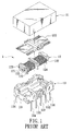
- U.S. Patent No. 4,881,053 discloses an electromagnetic relay 1 including a casing 11, an electromagnet block 12, and a base 13 that are sealed in the casing 11.
- the electromagnet block 12 includes a spool 121, two pairs of junction terminals 123 having coil winding portions 122 exposed from opposite longitudinal sides of the spool 121, and coils 124 wound on the spool 121.
- Each of the coils 124 has one end that is to be wound on one of the coil winding portions 122 of the corresponding pair of the junction terminals 123, and the other end that is to be wound on the other one of the coil winding portions 122 of the corresponding pair of the junction terminals 123.
- the base 13 includes a base body 131 for accommodating the electromagnet block 12, a pair of common terminals 132 and two pairs of fixed contact terminals 133 inserted into the base body 131 and spaced apart from each other, and two pairs of coil terminals 134 connected respectively and electrically to the junction terminals 123.
- An armature block 135 is connected electrically to the common terminals 132, and is supported pivotally by the electromagnet block 12.
- the armature block 135 When the armature block 135 is affected by an electromagnetic field generated by the electromagnet block 12, the armature block 135 is brought into contact with the left fixed contact terminals 133, so as to establish electrical connection between the common terminals 132 and the left fixed contact terminals 133 while breaking electrical connection between the common terminals 132 and the right fixed contact terminals 133.
- the electromagnetic relay 1 can serve as a switch unit.
- the size of the base body 131 is relatively large in order to accommodate the entire electromagnet block 12.
- the junction terminals 123 since there is no mechanism for fixing the electromagnet block 12 in the base body 131, it is difficult to connect the junction terminals 123 accurately to the coil terminals 134duringassembly.
- thecommon, fixedcontact, and coil terminals 132, 133, 134 are manually welded on both sides of the base body 131, so that the electromagnetic relay 1 cannot be fabricated at a high rate.
- EP0720194 discloses a method for manufacturing an electromagnetic relay in which a base block is monolithically molded to terminals and connector tabs provided in a lead frame. After separating the terminals from the lead frame and bending the terminals, a permanent magnet and an armature block are assembled into the base block. A case is then pressed down over the base block to separate the base block from the connector tabs of the lead frame.
- EP0313385 describes an electromagnetic relay comprising a U-shaped core carrying an energising coil between its poles.
- a magnet makes magnetic contact with a central part of the core, and provides at its free end a central fulcrum for an armature which is arranged to cooperate at its ends with the respective core poles.
- the fulcrum enables a see-saw movement of the armature about a biased neutral position.
- the document also discloses a method of assembling such an electromagnetic relay.
- an object of the present invention is to provide an electromagnetic relay that is easy to assemble and that can be fabricated at a high rate.
- an electromagnetic relay as defined in claim 1.
- an electromagnetic relay of the preferred embodiment of this invention includes a casing 2 and a relay core member including an electromagnetic unit 3 and a terminal unit 4.
- the casing 2 includes an upper casing body 21 and a bottom casing body 22 that are connected to each other by press fitting.
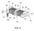
- the electromagnetic unit 3 is adapted for generating an electromagnetic field, and includes a spool frame set 31 having a pair of opposite first sides (31a) and a pair of opposite second sides (31b), a coil unit 32 being wound on the spool frame set 31 and including at least one coil 32', and a pair of coil winding pins 33.
- the spool frame set 31 includes a spool frame 310 wound with the coil unit 32, a pair of mounting frames 311, an iron core 312 attached fixedly to the spool frame 310, and a permanent magnet 313 inserted into the spool frame 310 and disposed on a middle portion of the iron core 312.
- Each of the mounting frames 311 is disposed at and extends along a respective one of the first sides (31a) of the spool frame set 31, and has a pair of through holes 315 formed therethrough and spaced apart from each other. Further, each of the mounting frames 311 includes an outer surface formed with a groove 314.
- Each of the coil winding pins 33 has a conductive portion 331, and a coil winding portion 332 extending along one of the second sides (31b) of the spool frame set 31.
- Each of the conductive portions 331 has a horizontal section being exposed from one of the mounting frames 311, and a vertical section extending into a corresponding one of the through holes 315.
- One end of each of the conductive portions 331 is aligned with an outer surface of the corresponding mounting frame 311, and the coil winding portions 332 of the coil winding pins 33 are disposedina space 316 defined by the mounting frames 311.
- the terminal unit 4 includes an engaging block 41 configured for accommodating the electromagnetic unit 3, a terminal set 42 inserted into the engaging block 41 and exposed from the bottom casing body 22 of the casing 2, and an armature component 43 being affected by the electromagnetic field generated by the electromagnetic unit 3 and serving as a switch mechanism by cooperating with the terminal set 42.
- the engaging block 41 includes a pair of opposite sidewalls 414 corresponding respectively to the first sides (31a) of the spool frame set 31, a pair of opposite side surfaces 415 corresponding respectively to the second sides (31b) of the spool frame set 31, a pair of barbs 411 disposed respectively on inner surfaces of the sidewalls 414, and a top surface 412 confronting the armature component 43.
- Each of the sidewalls 414 of the engaging block 41 is formed with a pair of notches 413, and the horizontal sections of the conductive portions 331 of the coil winding pins 33 are disposed respectively within the notches 413 (see Figure 10 ).
- Each of the barbs 411 is configured for engaging a corresponding one of the grooves 314 for preventing separation of the terminal unit 4 from the electromagnetic unit 3.
- the terminal set 42 includes a pair of common terminals 421, two pairs of fixed contact terminals 422, and two pairs of coil terminals 423. Each of the common, fixed contact and coil terminals 421, 422, 423 is inserted into the top surface 412, and has a portion extending along a corresponding one of the side surfaces 415.
- the engaging block 41 further includes two pairs of first welding points 424, 425 disposed on the top surface 412 thereof, and a pair of second welding points 426 disposed within the notches 413.
- the coil terminals 423 are respectively welded to the conductive portions 331 of the coil winding pins 33 at the second welding points 426 for forming electrical connection therebetween.
- the armature component 43 includes a middle contact portion 431 welded to the common terminals 421 at the welding points 424, 425 and supported pivotally by the spool frame set 31, and two pairs of movable contact portions 432, 433 disposed respectively at two opposite end portions of the armature component 43.
- a method for assembling the electromagnetic relay of the present invention includes the following steps.
- step 51 the coil winding pins 33 are inserted through the through holes 315 in one of the mounting frames 311 of the spool frame set 31, and the conductive portions 331 of the coil winding pins 33 are exposed from the through holes 315 as shown in Figure 5 .
- step 52 one end of the coil 32' is wound on the coil winding portion 332 of one of the coil winding pins 33, and the coil 32' is wound on the spool frame 310. Thereafter, in step 53 the other end of the coil 32' is wound on the coil winding portion 332 of the other one of the coil winding pins 33.
- the ends of the coil 32' can be fixed on the coil winding portions 332 of the coil winding pins 33 by welding with soldering tin.
- each of the coil winding portions 332 of the coil winding pins 33 is bent upwardly and toward the corresponding one of the second sides (31b) of the spool frame set 31 as shown in Figure 7 . Therefore, the spool frame set 31, the coil unit 32, and the coil winding pins 33 are assembled together to form the electromagnetic unit 3.
- the terminal set 42 is formed from a plate.
- the plate is embedded partially in the engaging block 41 such that it has a plurality of plate portions 421', 422', 423' corresponding to the terminals 421, 422, 423 (see Figure 3 ), and is then bent to form the terminals 421, 422, 423 such that upper ends of the coil terminals 423 are disposed respectively in the notches 413 in the engaging block 41.
- step 56 the electromagnetic unit 3 is inserted into the engaging block 41, and each of the grooves 314 in the mounting frames 311 of the spool frame set 31 engages a corresponding one of the barbs 411 of the engaging block 41. Therefore, the electromagnetic unit 3 and the terminal unit 4 are assembled together to form the relay core member.
- the coil terminals 423 of the terminal set 42 are respectively in electrical contact with the conductive portions 331 of the coil winding pins 33.
- One end of each of the conductive portions 331 of the coil winding pins 33 is aligned with the outer surface of the corresponding one of the mounting frames 311, and is disposed within the corresponding one of the notches 413.
- the coil winding portions 332 are disposed in the space 316 between the mounting frames 311.
- step 57 the common terminals 421 are welded to the middle contact portion 431 of the armature component 43, and the coil terminals 423 are welded to the conductive portions 331 of the coil winding pins 33 at the welding points 424, 425, 426, respectively, using laser welding method.
- step 58 the relay core member including the electromagnetic unit 3 and the terminal unit 4 is finally sealed in the casing 2, and the terminal set 42 is exposed from the bottom casing body 22 of the casing 2.
- each of the right movable contact portions 432 is pivoted to a connection position, where the corresponding right movable contact portion 432 is electrically connected to a corresponding one of the fixed contact terminals 422.
- the electromagnetic field is not generated, and therefore each of the right movable contact portions 432 of the armature component 43 is biased to a disconnection position, where the corresponding right movable contact portion 432 is separated from the corresponding one of the fixed contact terminals 422.
- the armature component 43 serves as a switch mechanism.
- the electromagnetic unit 3 can also include two pairs of the coil winding pins 33 (not shown), so that the electromagnetic relay of this invention serves as a double-pole-double-throw (DPDT) relay to transmit two control signals.
- DPDT double-pole-double-throw
- the electromagnetic relay of the present invention and the method for assembling the same have the following advantages.
- Second, the welding points 424, 425, 426 can be formed using laser welding method, such that the manufacturing process of the electromagnetic relay is relatively simple.
- each of the barbs 411 engages a corresponding one of the grooves 314 for preventing separation of the terminal unit 4 from the electromagnetic unit 3, so that the coil terminals 423 can be connected accurately to the coil winding pins 33 during assembly of the electromagnetic relay. Therefore, an automated manufacturing process can be utilized for the electromagnetic relay of the present invention.
Landscapes
- Physics & Mathematics (AREA)
- Electromagnetism (AREA)
- Electromagnets (AREA)
Claims (11)
- Ein elektromagnetisches Relais, das Folgendes umfasst:ein Gehäuse (2); undein in besagtem Gehäuse (2) abgesiegeltes Relais-Kernelement, das Folgendes umfasst:eine elektromagnetische Einheit (3), die zum Erzeugen eines elektromagnetischen Felds geeignet ist, wobei die besagte elektromagnetische Einheit (3) einen Spulenrahmensatz (31) umfasst, der ein Paar erster Seiten (31a) und ein Paar zweiter Seiten (31b), eine auf dem besagten Spulenrahmensatz (31) aufgewickelte Spuleneinheit (32) und ein Paar von Spulenwickelstiften (33) umfasst, wobei jeder Spulenwickelstift (33) eine von einer der besagten ersten Seiten (31a) frei gesetzte leitende Zone (331) sowie eine Spulenwickelzone (332) hat, die sich an einer der besagten zweiten Seiten entlang (31b) erstreckt, wobei der besagte Spulenrahmensatz (31) ferner ein Paar von Montagerahmen (311) umfasst, von denen sich jeder an einer jeweiligen der besagten ersten Seiten (31a) des besagten Spulenrahmensatzes (31) befindet und sich daran entlang erstreckt, sowieeine Klemmeneinheit (4), die einen zur Aufnahme der besagten elektromagnetischen Einheit (3) konfigurierten Einrückblock (41), einen vom besagten Gehäuse (2) frei gesetzten und teilweise im besagten Einrückblock (41) eingebetteten Klemmensatz (42) und eine Armaturenbaugruppe (43) umfasst, die unter dem Einfluss des von der besagten elektromagnetischen Einheit (3) erzeugten elektromagnetischen Felds steht und durch Kooperation mit dem besagten Klemmensatz (42) als Schaltmechanismus dient;dadurch gekennzeichnet, dass der besagte Einrückblock (41) ein Paar von Seitenwänden (414), die jeweils den besagten ersten Seiten (31a) des besagten Spulenrahmensatzes (31) entsprechen, sowie ein jeweils an besagten Seitenwänden (414) angeordnetes Paar von Kerben (411) umfasst;sowie dass jeder der besagten Montagerahmen (311) eine Außenfläche umfasst, in welcher eine Nut (314) geformt ist, die zum Eingreifen in eine entsprechende Kerbe der besagten Kerben (411) konfiguriert ist um zu verhindern, dass sich die besagte Klemmeneinheit (4) von der besagten elektromagnetischen Einheit (3) trennt;sowie dass der besagte Einrückblock (41) ein Paar von Einkerbungen (413) umfasst; unddass die besagte leitende Zone (331) eines jeden der besagten Spulenwickelstifte (33) innerhalb einer entsprechenden Einkerbung der besagten Einkerbungen (413) angeordnet ist.
- Das Anspruch 1 entsprechende elektromagnetische Relais, wobei jeder der besagten Montagerahmen (311) des besagten Spulenrahmensatzes (31) mit einem Paar von Durchgangslöchern (315) geformt ist, die jeweils durch einen entsprechenden Montagerahmen (311) der besagten Montagerahmen (311) geformt und voneinander beabstandet sind; und
wobei jede der besagten leitenden Zonen (331) einen von einem der besagten Montagerahmen (311) frei gesetzten horizontalen Abschnitt sowie einen vertikalen Abschnitt umfasst, der sich in ein entsprechendes Durchgangsloch (315) der besagten Durchgangslöcher (315) hinein erstreckt. - Das Anspruch 2 entsprechende elektromagnetische Relais, wobei die besagten horizontalen Abschnitte der besagten leitenden Zonen (331) der besagten Spulenwickelstifte (33) jeweils innerhalb der besagten Einkerbungen (413) und die besagten Spulenwickelzonen (332) der besagten Spulenwickelstifte (33) in einem von den besagten Montagerahmen (311) definierten Raum angeordnet sind.
- Das einem der Ansprüche 1 bis 3 entsprechende elektromagnetische Relais, bei welchem der besagte Einrückblock (41) ein Paar von Seitenwänden (415) und der besagte Klemmensatz (42) der besagten Klemmeneinheit (4) ein Paar üblicher Klemmen (421), zwei Paare Festkontaktklemmen (422) und zwei Paare Spulenklemmen (423) umfassen, wobei jede der besagten üblichen, der Festkontakt- und der Spulenklemmen (421, 422, 423) einen Abschnitt hat, der sich jeweils entlang einer entsprechenden Seitenwand (415) der besagten Seitenwände (415) erstreckt, während die besagten Spulenklemmen (423) jeweils mit den besagten leitenden leitenden Zonen (331) der besagten Spulenwickelstifte (33) elektrisch verbunden sind.
- Das Anspruch 4 entsprechende elektromagnetische Relais, wobei die besagte Armaturenbaugruppe (43) einen mit den besagten üblichen Klemmen (421) elektrisch verbundenen und vom besagten Spulenrahmensatz (31) drehbar unterstützten mittleren Kontaktabschnitt (431), sowie ein Paar beweglicher Kontaktteile (432, 433) umfasst, die jeweils an zwei Endabschnitten der besagten Armaturenbaugruppe (43) angeordnet sind, wobei jedes der besagten beweglichen Kontaktteile (432, 433) zwischen einer Verbindungsposition, in welcher ein entsprechendes Kontaktteil der besagten beweglichen Kontaktteile (432, 433) mit einer der besagten entsprechenden Festkontaktklemmen (422) elektrisch verbunden ist, und einer Abschaltposition drehbar versetzt werden kann, in welcher das entsprechende Kontaktteil der besagten beweglichen Kontaktteile (432, 433) von der entsprechenden Festkontaktklemme (422) der besagten Festkontaktklemmen (422) getrennt ist.
- Das Anspruch 5 entsprechende elektromagnetische Relais, wobei der besagte Einrückblock (41) der besagten Klemmeneinheit (4) eine Oberfläche (412) mit einer Vielzahl von Schweißpunkten (424, 425, 426) umfasst, und wobei die besagten üblichen Klemmen (421) am besagten mittleren Kontaktabschnitt (431) der besagten Armaturenbaugruppe (43) bzw. die besagten Spulenklemmen (423) jeweils an den besagten leitenden Zonen (331) der besagten Spulenwickelstifte (33) an besagten Schweißpunkten (424, 425, 426) angeschweißt sind.
- Das Anspruch 6 entsprechende elektromagnetische Relais, wobei die besagten Schweißpunkte (424, 425, 426) anhand des Laserschweißverfahrens gebildet werden.
- Das einem der Ansprüche 1 bis 7 entsprechende elektromagnetische Relais, wobei das besagte Gehäuse (2) einen oberen Gehäusekörper (21) und einen unteren Gehäusekörper (22) umfasst, die durch Einpressen miteinander verbunden sind, und wobei der besagte untere Gehäusekörper (22) ferner konfiguriert ist um zu ermöglichen, dass der besagte Klemmensatz (42) von diesem Gehäusekörper frei gesetzt wird.
- Ein Verfahren zum Zusammenbauen eines elektromagnetischen Relais, das ein Gehäuse (2), eine elektromagnetische Einheit (3) und eine Klemmeneinheit (4) umfasst, wobei die elektromagnetische Einheit (3) einen Spulenrahmensatz (31), eine Spuleneinheit (32) und ein Paar Spulenwickelstifte (33) umfasst, wobei die Klemmeneinheit (4) einen Einrückblock (41), einen in den besagten Einrückblock (41) eingebetteten Klemmensatz (42) und eine Armaturenbaugruppe (43) umfasst, die unter dem Einfluss eines von der besagten elektromagnetischen Einheit (3) erzeugten elektromagnetischen Felds steht und durch Kooperation mit dem Klemmensatz (42) als Schaltmechanismus dient, wobei das besagte Verfahren dadurch gekennzeichnet ist:a) dass die Spulenwickelstifte (33) jeweils durch ein Paar von Durchgangslöchern (315) im Spulenrahmensatz (31) eines Paars erster Seiten (31a) des Spulenrahmensatzes (31) eingeführt werden;b) dass ein Ende von der Spuleneinheit (32) auf einen der Spulenwickelstifte (33) gewickelt wird;c) dass die Spuleneinheit (32) auf den Spulenrahmensatz (31) gewickelt wird;d) dass das andere Ende von der Spuleneinheit (32) auf den anderen der Spulenwickelstifte (33) gewickelt wird;e) dass jeder der Spulenwickelstifte (33) derart nach oben und in Richtung eines entsprechenden Paars zweiter Seiten (31b) des Spulenrahmensatzes (31) gebogen wird, um den Spulenrahmensatz (31), die Spuleneinheit (32) und die Spulenwickelstifte (33) zusammenzubauen und so die elektromagnetische Einheit (3) zu bilden;f) dass die elektromagnetische Einheit (3) in den Einrückblock (41) der Klemmeneinheit (4) eingeführt wird, um den entsprechenden Eingriff zwischen einem Paar von Nuten (314) im Spulenrahmensatz (31) an den ersten Seiten (31a) und einem Paar von Kerben (411) zu ermöglichen, die jeweils auf einem Paar von Seitenwänden (414) des Einrückblocks (41) angeordnet sind, die jeweils den besagten ersten Seiten (31a) des besagten Spulenrahmensatzes (31) entsprechen, um die elektromagnetische Einheit (3) und den Einrückblock (41) zusammen mit dem Klemmensatz (42) in elektrischem Kontakt mit den Spulenwickelstiften (33) zusammenzubauen; undg) dass die elektromagnetische Einheit (3) und die Klemmeneinheit (4) im Gehäuse (2) abgesiegelt sind, um das elektromagnetische Relais zu bilden.
- Das Anspruch 9 entsprechende Verfahren, das ferner einen Schritt f1) umfasst, bei welchem der Klemmensatz (42) an der Armaturenbaugruppe (43) sowie die Spulenwickelstifte (33) nach dem Schritt f) an einer Vielzahl von Schweißpunkten (424, 425, 426) auf einer Oberfläche (412) des Einrückblocks (41) angeschweißt werden.
- Das Anspruch 10 entsprechende Verfahren, wobei das Schweißen des Klemmensatzes (42) bei Schritt f1) anhand des Laserschweißverfahrens vorgenommen wird.
Priority Applications (1)
| Application Number | Priority Date | Filing Date | Title |
|---|---|---|---|
| EP20090160229 EP2251886B1 (de) | 2009-05-14 | 2009-05-14 | Elektromagnetisches Relais und Montageverfahren dafür |
Applications Claiming Priority (1)
| Application Number | Priority Date | Filing Date | Title |
|---|---|---|---|
| EP20090160229 EP2251886B1 (de) | 2009-05-14 | 2009-05-14 | Elektromagnetisches Relais und Montageverfahren dafür |
Publications (2)
| Publication Number | Publication Date |
|---|---|
| EP2251886A1 EP2251886A1 (de) | 2010-11-17 |
| EP2251886B1 true EP2251886B1 (de) | 2014-04-09 |
Family
ID=41066466
Family Applications (1)
| Application Number | Title | Priority Date | Filing Date |
|---|---|---|---|
| EP20090160229 Not-in-force EP2251886B1 (de) | 2009-05-14 | 2009-05-14 | Elektromagnetisches Relais und Montageverfahren dafür |
Country Status (1)
| Country | Link |
|---|---|
| EP (1) | EP2251886B1 (de) |
Family Cites Families (8)
| Publication number | Priority date | Publication date | Assignee | Title |
|---|---|---|---|---|
| DE3338182A1 (de) * | 1983-10-20 | 1985-05-02 | Siemens AG, 1000 Berlin und 8000 München | Elektromagnetische relais und verfahren zu dessen herstellung |
| JPH02503844A (ja) * | 1987-06-16 | 1990-11-08 | ペッド・リミテッド | 電気的構成要素におけるかつそれに関する改良 |
| US4912438A (en) | 1987-10-22 | 1990-03-27 | Nec Corporation | Electromagnetic relay |
| JP3472881B2 (ja) * | 1993-02-24 | 2003-12-02 | オムロン株式会社 | 電磁継電器の製造方法 |
| US5880653A (en) | 1993-09-17 | 1999-03-09 | Omron Corporation | Electromagnetic relay and its manufacture |
| WO2000054296A1 (en) * | 1999-03-05 | 2000-09-14 | Omron Corporation | Electromagnetic relay |
| JP4334158B2 (ja) * | 2001-03-26 | 2009-09-30 | 富士通コンポーネント株式会社 | 電磁継電器 |
| JP4466506B2 (ja) * | 2005-08-12 | 2010-05-26 | オムロン株式会社 | リレー |
-
2009
- 2009-05-14 EP EP20090160229 patent/EP2251886B1/de not_active Not-in-force
Also Published As
| Publication number | Publication date |
|---|---|
| EP2251886A1 (de) | 2010-11-17 |
Similar Documents
| Publication | Publication Date | Title |
|---|---|---|
| JP5004244B2 (ja) | 電磁継電器 | |
| CN106057586B (zh) | 触点装置以及电磁继电器 | |
| JP5222669B2 (ja) | 電磁継電器 | |
| JP6037730B2 (ja) | 電磁継電器 | |
| US7994883B2 (en) | Electromagnetic relay | |
| JP5004243B2 (ja) | 電磁継電器 | |
| EP1174896A2 (de) | Elektromagnetisches Relais | |
| EP0902452B1 (de) | Elektromagnetisches Relais, Verbindung für eine Scharnierfederanordnung und ein Joch dieses Elektromagnetisches Relais | |
| CN113412528B (zh) | 继电器 | |
| EP0827171B1 (de) | Elektromagnetisches Relais | |
| JP5029536B2 (ja) | リレー装置 | |
| CN113544812B (zh) | 继电器 | |
| CN112582218A (zh) | 继电器 | |
| JP4693927B2 (ja) | 電磁継電器 | |
| JPH0559532B2 (de) | ||
| US7135946B2 (en) | Electromagnetic relay having at least one relay actuator and a receptacle for relay actuators | |
| EP1592036B1 (de) | Elektromagnetisches Relais | |
| EP2251886B1 (de) | Elektromagnetisches Relais und Montageverfahren dafür | |
| CN105830188A (zh) | 有极直流电磁铁装置和使用其的电磁接触器 | |
| CN102054626A (zh) | 线圈端 | |
| US4456896A (en) | Low cost relay | |
| JP3219416B2 (ja) | 電磁継電器 | |
| CN214378246U (zh) | 一种电磁继电器 | |
| CA1173086A (en) | Low cost relay | |
| EP1562209A2 (de) | Elektromagnetisches Relais mit mindestens einem Relaisbetätiger und einem Sockel für Relaisbetätiger |
Legal Events
| Date | Code | Title | Description |
|---|---|---|---|
| PUAI | Public reference made under article 153(3) epc to a published international application that has entered the european phase |
Free format text: ORIGINAL CODE: 0009012 |
|
| 17P | Request for examination filed |
Effective date: 20090514 |
|
| AK | Designated contracting states |
Kind code of ref document: A1 Designated state(s): AT BE BG CH CY CZ DE DK EE ES FI FR GB GR HR HU IE IS IT LI LT LU LV MC MK MT NL NO PL PT RO SE SI SK TR |
|
| GRAP | Despatch of communication of intention to grant a patent |
Free format text: ORIGINAL CODE: EPIDOSNIGR1 |
|
| INTG | Intention to grant announced |
Effective date: 20131128 |
|
| GRAS | Grant fee paid |
Free format text: ORIGINAL CODE: EPIDOSNIGR3 |
|
| GRAA | (expected) grant |
Free format text: ORIGINAL CODE: 0009210 |
|
| AK | Designated contracting states |
Kind code of ref document: B1 Designated state(s): AT BE BG CH CY CZ DE DK EE ES FI FR GB GR HR HU IE IS IT LI LT LU LV MC MK MT NL NO PL PT RO SE SI SK TR |
|
| REG | Reference to a national code |
Ref country code: GB Ref legal event code: FG4D |
|
| REG | Reference to a national code |
Ref country code: AT Ref legal event code: REF Ref document number: 661739 Country of ref document: AT Kind code of ref document: T Effective date: 20140415 Ref country code: CH Ref legal event code: EP |
|
| REG | Reference to a national code |
Ref country code: IE Ref legal event code: FG4D |
|
| REG | Reference to a national code |
Ref country code: DE Ref legal event code: R096 Ref document number: 602009023060 Country of ref document: DE Effective date: 20140522 |
|
| REG | Reference to a national code |
Ref country code: AT Ref legal event code: MK05 Ref document number: 661739 Country of ref document: AT Kind code of ref document: T Effective date: 20140409 |
|
| REG | Reference to a national code |
Ref country code: NL Ref legal event code: VDEP Effective date: 20140409 |
|
| REG | Reference to a national code |
Ref country code: LT Ref legal event code: MG4D |
|
| PG25 | Lapsed in a contracting state [announced via postgrant information from national office to epo] |
Ref country code: GR Free format text: LAPSE BECAUSE OF FAILURE TO SUBMIT A TRANSLATION OF THE DESCRIPTION OR TO PAY THE FEE WITHIN THE PRESCRIBED TIME-LIMIT Effective date: 20140710 Ref country code: FI Free format text: LAPSE BECAUSE OF FAILURE TO SUBMIT A TRANSLATION OF THE DESCRIPTION OR TO PAY THE FEE WITHIN THE PRESCRIBED TIME-LIMIT Effective date: 20140409 Ref country code: NL Free format text: LAPSE BECAUSE OF FAILURE TO SUBMIT A TRANSLATION OF THE DESCRIPTION OR TO PAY THE FEE WITHIN THE PRESCRIBED TIME-LIMIT Effective date: 20140409 Ref country code: LT Free format text: LAPSE BECAUSE OF FAILURE TO SUBMIT A TRANSLATION OF THE DESCRIPTION OR TO PAY THE FEE WITHIN THE PRESCRIBED TIME-LIMIT Effective date: 20140409 Ref country code: NO Free format text: LAPSE BECAUSE OF FAILURE TO SUBMIT A TRANSLATION OF THE DESCRIPTION OR TO PAY THE FEE WITHIN THE PRESCRIBED TIME-LIMIT Effective date: 20140709 Ref country code: BG Free format text: LAPSE BECAUSE OF FAILURE TO SUBMIT A TRANSLATION OF THE DESCRIPTION OR TO PAY THE FEE WITHIN THE PRESCRIBED TIME-LIMIT Effective date: 20140709 Ref country code: IS Free format text: LAPSE BECAUSE OF FAILURE TO SUBMIT A TRANSLATION OF THE DESCRIPTION OR TO PAY THE FEE WITHIN THE PRESCRIBED TIME-LIMIT Effective date: 20140809 |
|
| PG25 | Lapsed in a contracting state [announced via postgrant information from national office to epo] |
Ref country code: SE Free format text: LAPSE BECAUSE OF FAILURE TO SUBMIT A TRANSLATION OF THE DESCRIPTION OR TO PAY THE FEE WITHIN THE PRESCRIBED TIME-LIMIT Effective date: 20140409 Ref country code: PL Free format text: LAPSE BECAUSE OF FAILURE TO SUBMIT A TRANSLATION OF THE DESCRIPTION OR TO PAY THE FEE WITHIN THE PRESCRIBED TIME-LIMIT Effective date: 20140409 Ref country code: LV Free format text: LAPSE BECAUSE OF FAILURE TO SUBMIT A TRANSLATION OF THE DESCRIPTION OR TO PAY THE FEE WITHIN THE PRESCRIBED TIME-LIMIT Effective date: 20140409 Ref country code: HR Free format text: LAPSE BECAUSE OF FAILURE TO SUBMIT A TRANSLATION OF THE DESCRIPTION OR TO PAY THE FEE WITHIN THE PRESCRIBED TIME-LIMIT Effective date: 20140409 Ref country code: AT Free format text: LAPSE BECAUSE OF FAILURE TO SUBMIT A TRANSLATION OF THE DESCRIPTION OR TO PAY THE FEE WITHIN THE PRESCRIBED TIME-LIMIT Effective date: 20140409 Ref country code: ES Free format text: LAPSE BECAUSE OF FAILURE TO SUBMIT A TRANSLATION OF THE DESCRIPTION OR TO PAY THE FEE WITHIN THE PRESCRIBED TIME-LIMIT Effective date: 20140409 |
|
| PG25 | Lapsed in a contracting state [announced via postgrant information from national office to epo] |
Ref country code: PT Free format text: LAPSE BECAUSE OF FAILURE TO SUBMIT A TRANSLATION OF THE DESCRIPTION OR TO PAY THE FEE WITHIN THE PRESCRIBED TIME-LIMIT Effective date: 20140811 |
|
| REG | Reference to a national code |
Ref country code: CH Ref legal event code: PL |
|
| REG | Reference to a national code |
Ref country code: DE Ref legal event code: R097 Ref document number: 602009023060 Country of ref document: DE |
|
| PG25 | Lapsed in a contracting state [announced via postgrant information from national office to epo] |
Ref country code: CZ Free format text: LAPSE BECAUSE OF FAILURE TO SUBMIT A TRANSLATION OF THE DESCRIPTION OR TO PAY THE FEE WITHIN THE PRESCRIBED TIME-LIMIT Effective date: 20140409 Ref country code: LI Free format text: LAPSE BECAUSE OF NON-PAYMENT OF DUE FEES Effective date: 20140531 Ref country code: SK Free format text: LAPSE BECAUSE OF FAILURE TO SUBMIT A TRANSLATION OF THE DESCRIPTION OR TO PAY THE FEE WITHIN THE PRESCRIBED TIME-LIMIT Effective date: 20140409 Ref country code: RO Free format text: LAPSE BECAUSE OF FAILURE TO SUBMIT A TRANSLATION OF THE DESCRIPTION OR TO PAY THE FEE WITHIN THE PRESCRIBED TIME-LIMIT Effective date: 20140409 Ref country code: BE Free format text: LAPSE BECAUSE OF FAILURE TO SUBMIT A TRANSLATION OF THE DESCRIPTION OR TO PAY THE FEE WITHIN THE PRESCRIBED TIME-LIMIT Effective date: 20140409 Ref country code: EE Free format text: LAPSE BECAUSE OF FAILURE TO SUBMIT A TRANSLATION OF THE DESCRIPTION OR TO PAY THE FEE WITHIN THE PRESCRIBED TIME-LIMIT Effective date: 20140409 Ref country code: MC Free format text: LAPSE BECAUSE OF FAILURE TO SUBMIT A TRANSLATION OF THE DESCRIPTION OR TO PAY THE FEE WITHIN THE PRESCRIBED TIME-LIMIT Effective date: 20140409 Ref country code: DK Free format text: LAPSE BECAUSE OF FAILURE TO SUBMIT A TRANSLATION OF THE DESCRIPTION OR TO PAY THE FEE WITHIN THE PRESCRIBED TIME-LIMIT Effective date: 20140409 Ref country code: CH Free format text: LAPSE BECAUSE OF NON-PAYMENT OF DUE FEES Effective date: 20140531 |
|
| PLBE | No opposition filed within time limit |
Free format text: ORIGINAL CODE: 0009261 |
|
| STAA | Information on the status of an ep patent application or granted ep patent |
Free format text: STATUS: NO OPPOSITION FILED WITHIN TIME LIMIT |
|
| REG | Reference to a national code |
Ref country code: IE Ref legal event code: MM4A |
|
| REG | Reference to a national code |
Ref country code: FR Ref legal event code: ST Effective date: 20150130 |
|
| 26N | No opposition filed |
Effective date: 20150112 |
|
| GBPC | Gb: european patent ceased through non-payment of renewal fee |
Effective date: 20140709 |
|
| PG25 | Lapsed in a contracting state [announced via postgrant information from national office to epo] |
Ref country code: IT Free format text: LAPSE BECAUSE OF FAILURE TO SUBMIT A TRANSLATION OF THE DESCRIPTION OR TO PAY THE FEE WITHIN THE PRESCRIBED TIME-LIMIT Effective date: 20140409 |
|
| REG | Reference to a national code |
Ref country code: DE Ref legal event code: R097 Ref document number: 602009023060 Country of ref document: DE Effective date: 20150112 |
|
| PG25 | Lapsed in a contracting state [announced via postgrant information from national office to epo] |
Ref country code: IE Free format text: LAPSE BECAUSE OF NON-PAYMENT OF DUE FEES Effective date: 20140514 |
|
| PG25 | Lapsed in a contracting state [announced via postgrant information from national office to epo] |
Ref country code: FR Free format text: LAPSE BECAUSE OF NON-PAYMENT OF DUE FEES Effective date: 20140610 Ref country code: GB Free format text: LAPSE BECAUSE OF NON-PAYMENT OF DUE FEES Effective date: 20140709 |
|
| PG25 | Lapsed in a contracting state [announced via postgrant information from national office to epo] |
Ref country code: SI Free format text: LAPSE BECAUSE OF FAILURE TO SUBMIT A TRANSLATION OF THE DESCRIPTION OR TO PAY THE FEE WITHIN THE PRESCRIBED TIME-LIMIT Effective date: 20140409 |
|
| PG25 | Lapsed in a contracting state [announced via postgrant information from national office to epo] |
Ref country code: MT Free format text: LAPSE BECAUSE OF FAILURE TO SUBMIT A TRANSLATION OF THE DESCRIPTION OR TO PAY THE FEE WITHIN THE PRESCRIBED TIME-LIMIT Effective date: 20140409 |
|
| PG25 | Lapsed in a contracting state [announced via postgrant information from national office to epo] |
Ref country code: CY Free format text: LAPSE BECAUSE OF FAILURE TO SUBMIT A TRANSLATION OF THE DESCRIPTION OR TO PAY THE FEE WITHIN THE PRESCRIBED TIME-LIMIT Effective date: 20140409 |
|
| PG25 | Lapsed in a contracting state [announced via postgrant information from national office to epo] |
Ref country code: LU Free format text: LAPSE BECAUSE OF NON-PAYMENT OF DUE FEES Effective date: 20140514 Ref country code: TR Free format text: LAPSE BECAUSE OF FAILURE TO SUBMIT A TRANSLATION OF THE DESCRIPTION OR TO PAY THE FEE WITHIN THE PRESCRIBED TIME-LIMIT Effective date: 20140409 Ref country code: HU Free format text: LAPSE BECAUSE OF FAILURE TO SUBMIT A TRANSLATION OF THE DESCRIPTION OR TO PAY THE FEE WITHIN THE PRESCRIBED TIME-LIMIT; INVALID AB INITIO Effective date: 20090514 |
|
| PG25 | Lapsed in a contracting state [announced via postgrant information from national office to epo] |
Ref country code: MK Free format text: LAPSE BECAUSE OF FAILURE TO SUBMIT A TRANSLATION OF THE DESCRIPTION OR TO PAY THE FEE WITHIN THE PRESCRIBED TIME-LIMIT Effective date: 20140409 |
|
| REG | Reference to a national code |
Ref country code: DE Ref legal event code: R082 Ref document number: 602009023060 Country of ref document: DE Representative=s name: PAGE, WHITE & FARRER GERMANY LLP, DE |
|
| PGFP | Annual fee paid to national office [announced via postgrant information from national office to epo] |
Ref country code: DE Payment date: 20210503 Year of fee payment: 13 |
|
| REG | Reference to a national code |
Ref country code: DE Ref legal event code: R119 Ref document number: 602009023060 Country of ref document: DE |
|
| PG25 | Lapsed in a contracting state [announced via postgrant information from national office to epo] |
Ref country code: DE Free format text: LAPSE BECAUSE OF NON-PAYMENT OF DUE FEES Effective date: 20221201 |