EP2251894A2 - Hochdruck-Entladungslampe - Google Patents
Hochdruck-Entladungslampe Download PDFInfo
- Publication number
- EP2251894A2 EP2251894A2 EP10161680A EP10161680A EP2251894A2 EP 2251894 A2 EP2251894 A2 EP 2251894A2 EP 10161680 A EP10161680 A EP 10161680A EP 10161680 A EP10161680 A EP 10161680A EP 2251894 A2 EP2251894 A2 EP 2251894A2
- Authority
- EP
- European Patent Office
- Prior art keywords
- sealing
- discharge lamp
- pressure discharge
- metal
- ceramics
- Prior art date
- Legal status (The legal status is an assumption and is not a legal conclusion. Google has not performed a legal analysis and makes no representation as to the accuracy of the status listed.)
- Withdrawn
Links
Images


Classifications
-
- H—ELECTRICITY
- H01—ELECTRIC ELEMENTS
- H01J—ELECTRIC DISCHARGE TUBES OR DISCHARGE LAMPS
- H01J61/00—Gas-discharge or vapour-discharge lamps
- H01J61/02—Details
- H01J61/36—Seals between parts of vessels; Seals for leading-in conductors; Leading-in conductors
- H01J61/366—Seals for leading-in conductors
-
- H—ELECTRICITY
- H01—ELECTRIC ELEMENTS
- H01J—ELECTRIC DISCHARGE TUBES OR DISCHARGE LAMPS
- H01J61/00—Gas-discharge or vapour-discharge lamps
- H01J61/82—Lamps with high-pressure unconstricted discharge having a cold pressure > 400 Torr
Definitions
- an inner surface of a small-diameter cylindrical portion at the sealing portion is formed of poly-crystalline aluminum ceramics having an average crystal grain size of 50 micrometers or less.
- the high melting point metal diffuse in the fusion portion as the alumina grain growth control additives
- the sealing portion of the small-diameter cylindrical portion can be also formed using the translucent poly-crystalline alumina ceramics which contains the sintering additives beforehand. That is, it is also possible to make the sintering additives enter into the alumina crystal grain boundaries in this method when the alumina ceramics is melted. In this method, a portion of the sintering additives evaporates and disappears when the alumina ceramics is melted. Since the concentration of the sintering additives in the fuse portion fall more comparing to other portions, it turns out that the sintering additives contained in the translucent crystalline alumina ceramics in the fusion portion function as the alumina grain growth control additives.
- the alumina grain growth control additives it is possible to use both the high melting point metal and the sintering additives as the alumina grain growth control additives in the sealing portion.
- the effect of the alumina crystal grain-growth control is superior to the case where only one of the high melting point metal and the sintering additives is used.
- the crack generation of the sealing portion is reduced.
- the largest width size of the alumina crystal grain measured by the picture is made into a major axis L, and when the largest size is made into the minor axis W among width sizes of the direction which intersects perpendicularly with the major axis L, the minor axis W is equivalent to a diameter of an alumina crystal grain.
- the crack generation of the sealing portion can be controlled by managing the alumina crystal grain size and form.
- the grain size is not less than 5 micrometers, and the grain shape satisfies 1.0 ⁇ L/W ⁇ 10. Within the above conditions, the higher control effect is acquired to reduce the crack generation of the sealing portion.
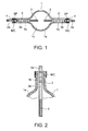
- the translucent ceramics airtight vessel 1 includes an envelopment portion 1a and a small diameter cylindrical portion 1b.
- the electric discharge space 1c is formed in the inside of the envelopment portion 1a.
- the "translucent" means a light transmittance state to such an extent that the light generated by electric discharge is penetrated and can be derived to the outside.
- the translucent ceramics does not necessarily have a transparent characteristic, but may have a light diffusion characteristic.
- the main portion of the envelopment portion 1a which surrounds a space for the discharging be translucent, other portions than the above-mentioned main portion is not necessarily to be translucent.
- the small-diameter cylindrical portion 1b is formed in a cylindrical shape with a small diameter and connected to an end of the envelopment portion 1a. Furthermore, the inside of the small-diameter cylindrical portion 1b is connected with the inside of the envelopment portion 1a in air tight extending from the end of the envelopment portion 1a to the outside.
- the small-diameter cylindrical portion 1b is integrally fabricated with the envelopment portion 1a by continuous curved surface.
- a pair of electrodes 3 is provided to generate electric discharge of the electric discharge medium later mentioned in the inside of the translucent ceramics airtight vessel 1.
- the pair of electrodes 3 is arranged facing and apart from each other so that arc discharge is generated between the electrodes 3
- the electrode shaft portion When the electrode 3 is equipped with the electrode shaft portion, the electrode shaft portion is formed with the electrode main portion in one unit or welded to the electrode main portion, and then connected to the halogen-resistant portion 2b of the current introducing conductor 2.
- the electrode shaft portion may be formed in unit with the halogen-resistant portion 2b of the current introducing conductor 2 by a single tungsten material depending on the case.
- the sealing portion SP is formed of the aluminum ceramics of the small-diameter cylindrical portion 1b, as shown by enlarging in Fig. 3 .
- the aluminum ceramics contains the alumina grain growth control additives.
- the aluminum ceramics melts while containing the high melting point metal diffused from the high melting point metal covering MC as the alumina grain growth control additives, and forming a fusion portion 4 after solidified in the sealing metal portion 2a.
- the fusion portion 4 includes a fused portion 4a, an adhesion portion 4b, and a stick portion 4c.
- the stick portion 4c is formed so that only a perimeter side surface of the small-diameter cylindrical portion 1b is softened or melted, and is adhered to the high melting point metal covering MC.
- the sealing portion SP does not necessary have the stick portion 4c.
- the high melting point metal covering MC is arranged in advance of the sealing of the translucent ceramics airtight vessel 1. After diffusing of the high melting point metal in the fusion portion 4 and forming the sealing portion SP, it is preferable that the most of the metal covering MC remains still. However, depending on the seal conditions, even if a portion of the metal covering MC dissociates, and the original form collapses, there is no influence in the characteristic.
- the process to form the sealing portion SP by the fusion of the alumina ceramics is not limited.
- the temperature of alumina ceramics is raised more than the fusion temperature, and the alumina ceramics melts.
- the melted alumina ceramics becomes fit to connection ends of respective of the sealing metal portion 2a and the halogen-resistant portion 2b corresponding to the sealing portion of the current introducing conductor 2, which is inserted in the small-diameter cylindrical portion 1b, while the high melting point metal is diffused in the alumina ceramics from the high melting point metal covering MC.
- the heating is stopped and cooled, the melted alumina ceramics of the fit portion is solidified, and the alumina ceramics of the fusion portion 4 is adhered to the respective connection ends of the sealing metal portion 2a and the halogen-resistant portion 2b of the current introducing conductor 2. Finally, the sealing portion SP is formed, and the translucent ceramics airtight vessel 1 is sealed.
- a local heating means of a heat ray projection type such as a laser or a halogen bulb with a reflector, an induction-heating means, and an electric heater, etc.
- a local heating means of a heat ray projection type such as a laser or a halogen bulb with a reflector, an induction-heating means, and an electric heater, etc.
- laser for example, YAG laser or CO 2 laser, etc. is used, for example.
- the local heating means When heating entire circumference of the sealing portion SP of the small-diameter cylindrical portion 1b using the local heating means of the heat ray projection type, if the metal mesh body is used as the high melting point metal covering MC, for example, the local heating means is arranged in the side of the sealing portion SP apart from a predetermined distance. If at least, either one of the small-diameter cylindrical portion 1b of the translucent ceramic airtight vessel 1 and the local heating means is rotated while operating the local heating means, the entire circumference of the small-diameter cylindrical portion 1b can be heated uniformly.
- the laser can be irradiated from a direction where the small-diameter cylindrical portion 1b extends, that is, a direction of a tube axis.
- the translucent ceramic airtight vessel 1 can be heated by fixedly arranging two or more local heating means around the small-diameter cylindrical portion arranged 16, or rotating the two or more local heating means around the circumference of the small-diameter cylindrical portion 1b.
- the translucent ceramic airtight vessel 1 can also be heated in the state where it remains at rest, by arranging the heating means so as to surround the entire circumference of the small-diameter cylindrical portion 1b.
- the halide of luminous metal mainly emits visible light, and which may be any of various known metal halides. That is, the metal halide of aluminous metal may be arbitrarily selected from a group of known metal halides as desired so as to achieve radiation of visible light with desired emission characteristics such as a general color rendering index Ra and luminous efficiency, further depending on the size or input power of the translucent ceramics discharge vessel 1.
- one or more halides may be selected from a group of sodium (Na), scandium (Sc), a rare earth metal (dysprosium (Dy), thulium (Tm), holmium (Ho), praseodymium (Pr), lantern (La), or cerium (Ce), or the like), thallium (Tl), indium (In), and lithium (Li).
- a rare earth metal dysprosium (Dy), thulium (Tm), holmium (Ho), praseodymium (Pr), lantern (La), or cerium (Ce), or the like
- Tl thallium
- indium (In) indium
- Li lithium
- a lamp voltage formation medium is effective in forming a lamp voltage, for example, may be mercury or a halide listed below.
- the halide as a lamp voltage forming medium is preferably halide of metals such as aluminum, (Al), iron ( Fe), zinc (Zn), antimony (Sb), or manganese (Mn) which serve to generate a relatively high vapor pressure during lighting and which emits a smaller quantity of light in the above visible region than the above luminous metal.
- the rare gas acts as a starting gas or a buffer gas and may be xenon (Xe), argon (Ar), krypton (Kr), or neon (Ne) singly or a mixture of any of them.
- compositions of the electric discharge medium for obtaining desired luminescence is as follows.
- the high-pressure discharge lamp 1 of the present invention may be integrated with a reflector.
- Fig. 4 is a cross-sectional view showing an enlarged sealing portion of the high-pressure discharge lamp.
- the sintering additives exist in the crystal grain boundary of the alumina ceramics intensively as alumina grain growth control additives in the fusion portion 4 of the sealing portion SP formed in the small-diameter cylindrical portion 1b of the translucent ceramics airtight vessel 1.
- content amount is a range of 50-500 ppm.
- the sintering additives are adhered at the external surface of the sealing portion SP in the small-diameter cylindrical portion 1b in advance of the sealing process.
- the sintering additives may be contained in the raw material of the alumina ceramics.
- the high melting point metal is also contained in the sealing portion SP as the alumina grain growth control additives in addition to the sintering additives, more superior crack prevention effect can be acquired.
- the rate of a content ratio of the high melting point metal in this embodiment it is preferable that the content ratio is the range of 0.5-30 mass %.
- a high-pressure discharge lamp of a third embodiment according to the present invention is explained with reference to Figs. 5 and 6 .
- a void V is easy to be formed by a gas of organic nature emitted from the alumina ceramics in the sealing portion SP. If the void V exceeds a predetermined size, the crack is easily generated.
- the diameter of the alumina crystal grain in the fusion portion 4 in the sealing portion SP is set to 3-200 micrometers, more preferably 10-150 micrometers.
- a ratio of an L/W, here the minor axis and the major axis are respectively denoted as W and L, is set to a range 1.0 ⁇ L/W ⁇ 20 and more preferably, a range 1.5 ⁇ L/W ⁇ 10.
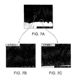
- Fig. 7 shows cross-sectional electron microscopic pictures of the sealing portion 4.
- Fig. 7A shows a cross-sectional picture of the fusion portion 4, in which the grain boundary crevices are formed in a portion.
- Fig. 7B shows a cross-sectional picture of the fusion portion 4, enlarging the portion in Fig. 7A , in which the grain boundary crevices are formed.
- Fig. 7C shows a cross-sectional picture of the fusion portion 4, by enlarging a portion in Fig. 7A , in which the grain boundary crevices are not formed.
- portions in which variant grain boundaries are appeared in black lines are grain boundary crevices of the alumina ceramics.
- the grain boundary crevice Since the grain boundary crevice is not connected with the exterior of the fusion portion 4, the grain boundary crevice is distinguished from the crack, and even if the grain boundary crevice is formed, it does not cause direct leak. However, if the grain boundary crevice is formed, a risk of resulting in the crack generation in a life is generated. Therefore, it is preferable that the grain boundary crevice is not formed.
- Example No.1 A lighting examination of 10,000 hours was done to inspect the existence of the crack generation about two samples in which a first sample (sample No.1) does not contain the grain boundary crevice, and a second sample (sample No.2) contains the grain boundary crevice.
- the high-pressure discharge lamp specifications are the same as those of Example 1.
- Table 3 The definition of the evaluation result is as follows.
- the poly-crystalline alumina ceramics in the fused portion 4 of the small-diameter cylindrical portion 1b contains the alumina grain growth control additives, the growth of the alumina crystal grain in the formation process of the sealing portion is suppressed. Therefore, the difference of the thermal expansion of the alumina ceramics of the sealing portion SP and the current introducing conductor 2 becomes small, and the high-pressure discharge lamp in which the crack generation of the sealing portion is suppressed can be offered.
- either one of the metal mesh body and the metal foil as the high melting point metal covering MC can be used, it becomes possible to easily diffuse the high melting point metal into the aluminum ceramics as the alumina grain growth control additives when the small-diameter cylindrical portion 1b is heated.
Landscapes
- Vessels And Coating Films For Discharge Lamps (AREA)
Applications Claiming Priority (2)
| Application Number | Priority Date | Filing Date | Title |
|---|---|---|---|
| JP2009118853 | 2009-05-15 | ||
| JP2009216091A JP2010287555A (ja) | 2009-05-15 | 2009-09-17 | 高圧放電ランプ |
Publications (2)
| Publication Number | Publication Date |
|---|---|
| EP2251894A2 true EP2251894A2 (de) | 2010-11-17 |
| EP2251894A3 EP2251894A3 (de) | 2012-04-04 |
Family
ID=42668194
Family Applications (1)
| Application Number | Title | Priority Date | Filing Date |
|---|---|---|---|
| EP10161680A Withdrawn EP2251894A3 (de) | 2009-05-15 | 2010-04-30 | Hochdruck-Entladungslampe |
Country Status (3)
| Country | Link |
|---|---|
| EP (1) | EP2251894A3 (de) |
| JP (1) | JP2010287555A (de) |
| CN (1) | CN101887838B (de) |
Families Citing this family (1)
| Publication number | Priority date | Publication date | Assignee | Title |
|---|---|---|---|---|
| CN110094647A (zh) * | 2018-01-29 | 2019-08-06 | 深圳市绎立锐光科技开发有限公司 | 一种波长转换装置、发光组件及照明装置 |
Citations (2)
| Publication number | Priority date | Publication date | Assignee | Title |
|---|---|---|---|---|
| JP2007115651A (ja) | 2005-06-14 | 2007-05-10 | Toshiba Lighting & Technology Corp | 高圧放電ランプ、高圧放電ランプ点灯装置および照明装置 |
| JP2009009921A (ja) | 2007-05-29 | 2009-01-15 | Toshiba Lighting & Technology Corp | ランプ |
Family Cites Families (9)
| Publication number | Priority date | Publication date | Assignee | Title |
|---|---|---|---|---|
| DE68927594T2 (de) * | 1988-05-13 | 1997-07-24 | Gte Prod Corp | Bogenkolben für Hochdruckmetalldampfentladungslampen, Lampe mit einem solchen Kolben und Verfahren zur Herstellung |
| US5426343A (en) * | 1992-09-16 | 1995-06-20 | Gte Products Corporation | Sealing members for alumina arc tubes and method of making the same |
| JP4613408B2 (ja) * | 1999-10-15 | 2011-01-19 | 日本碍子株式会社 | 高圧放電灯用発光管の製造方法 |
| JP4135050B2 (ja) * | 1999-12-08 | 2008-08-20 | 東芝ライテック株式会社 | 高圧放電ランプ、高圧放電ランプ点灯装置および照明装置 |
| JP2006221928A (ja) * | 2005-02-09 | 2006-08-24 | Toshiba Lighting & Technology Corp | 高圧放電ランプ |
| US7378799B2 (en) * | 2005-11-29 | 2008-05-27 | General Electric Company | High intensity discharge lamp having compliant seal |
| DE102006024238A1 (de) * | 2006-05-23 | 2007-11-29 | Patent-Treuhand-Gesellschaft für elektrische Glühlampen mbH | Hochdruckentladungslampe |
| US7952285B2 (en) * | 2006-08-18 | 2011-05-31 | Koninklijke Philips Electronics N.V. | Metal halide lamp with cerium oxide seal |
| US7741780B2 (en) * | 2007-02-26 | 2010-06-22 | Osram Sylvania Inc. | Ceramic discharge vessel having a sealing composition |
-
2009
- 2009-09-17 JP JP2009216091A patent/JP2010287555A/ja active Pending
-
2010
- 2010-04-30 EP EP10161680A patent/EP2251894A3/de not_active Withdrawn
- 2010-05-14 CN CN2010101806252A patent/CN101887838B/zh not_active Expired - Fee Related
Patent Citations (2)
| Publication number | Priority date | Publication date | Assignee | Title |
|---|---|---|---|---|
| JP2007115651A (ja) | 2005-06-14 | 2007-05-10 | Toshiba Lighting & Technology Corp | 高圧放電ランプ、高圧放電ランプ点灯装置および照明装置 |
| JP2009009921A (ja) | 2007-05-29 | 2009-01-15 | Toshiba Lighting & Technology Corp | ランプ |
Also Published As
| Publication number | Publication date |
|---|---|
| CN101887838A (zh) | 2010-11-17 |
| EP2251894A3 (de) | 2012-04-04 |
| JP2010287555A (ja) | 2010-12-24 |
| CN101887838B (zh) | 2012-04-25 |
Similar Documents
| Publication | Publication Date | Title |
|---|---|---|
| US6882109B2 (en) | Electric discharge lamp | |
| JP2008529220A (ja) | セラミックハロゲン化金属ランプ | |
| EP1289001A2 (de) | Hochdruckentladungslampen und Verfahren zur Herstellung einer Hochdruckentladungslampe | |
| CN1950925B (zh) | 具有优化形状的陶瓷金属卤化物灯具 | |
| EP0971043B1 (de) | Cermet und keramische Entladungslampe | |
| JP3922452B2 (ja) | 接合体、高圧放電灯用組み立て体および高圧放電灯 | |
| US7852006B2 (en) | Ceramic lamp having molybdenum-rhenium end cap and systems and methods therewith | |
| EP2251894A2 (de) | Hochdruck-Entladungslampe | |
| JP2000285849A (ja) | 放電灯用電極とその製造方法、およびそれを用いた放電灯 | |
| JP4832931B2 (ja) | 冷陰極管用焼結電極の製造方法 | |
| US20080211411A1 (en) | High-pressure discharge lamp, high-pressure discharge lamp operating apparatus, and illuminating apparatus | |
| JP5100632B2 (ja) | 冷陰極管用焼結電極およびそれを用いた冷陰極管並びに液晶表示装置 | |
| US8310157B2 (en) | Lamp having metal conductor bonded to ceramic leg member | |
| JP2002326878A (ja) | 接合体および高圧放電灯 | |
| JPH11273626A (ja) | セラミック製放電ランプ | |
| JP2009009921A (ja) | ランプ | |
| EP1160831A1 (de) | Entladungslampe | |
| CN100382228C (zh) | 金属卤灯 | |
| JP2008103320A (ja) | 高圧放電ランプ、高圧放電ランプ点灯装置および照明装置 | |
| JP2009110769A (ja) | 高圧放電ランプ | |
| KR20080077590A (ko) | 냉음극 형광 램프 및 냉음극 형광 램프의 제조 방법 | |
| JP2005203177A (ja) | 高圧放電ランプおよび照明装置 | |
| JP2008288043A (ja) | 放電ランプ | |
| JP2008177151A (ja) | 高圧放電ランプ、高圧放電ランプ点灯装置および照明装置 | |
| JP2001243911A (ja) | 高圧放電ランプおよび照明装置 |
Legal Events
| Date | Code | Title | Description |
|---|---|---|---|
| PUAI | Public reference made under article 153(3) epc to a published international application that has entered the european phase |
Free format text: ORIGINAL CODE: 0009012 |
|
| 17P | Request for examination filed |
Effective date: 20100504 |
|
| AK | Designated contracting states |
Kind code of ref document: A2 Designated state(s): AT BE BG CH CY CZ DE DK EE ES FI FR GB GR HR HU IE IS IT LI LT LU LV MC MK MT NL NO PL PT RO SE SI SK SM TR |
|
| AX | Request for extension of the european patent |
Extension state: AL BA ME RS |
|
| PUAL | Search report despatched |
Free format text: ORIGINAL CODE: 0009013 |
|
| AK | Designated contracting states |
Kind code of ref document: A3 Designated state(s): AT BE BG CH CY CZ DE DK EE ES FI FR GB GR HR HU IE IS IT LI LT LU LV MC MK MT NL NO PL PT RO SE SI SK SM TR |
|
| AX | Request for extension of the european patent |
Extension state: AL BA ME RS |
|
| RIC1 | Information provided on ipc code assigned before grant |
Ipc: H01J 61/36 20060101AFI20120229BHEP |
|
| STAA | Information on the status of an ep patent application or granted ep patent |
Free format text: STATUS: THE APPLICATION IS DEEMED TO BE WITHDRAWN |
|
| 18D | Application deemed to be withdrawn |
Effective date: 20121005 |