EP2252000A2 - Optical WDM transmission and reception device and optical transceiver unit for same - Google Patents
Optical WDM transmission and reception device and optical transceiver unit for same Download PDFInfo
- Publication number
- EP2252000A2 EP2252000A2 EP10002951A EP10002951A EP2252000A2 EP 2252000 A2 EP2252000 A2 EP 2252000A2 EP 10002951 A EP10002951 A EP 10002951A EP 10002951 A EP10002951 A EP 10002951A EP 2252000 A2 EP2252000 A2 EP 2252000A2
- Authority
- EP
- European Patent Office
- Prior art keywords
- unit
- optical
- signal
- tuning
- channel
- Prior art date
- Legal status (The legal status is an assumption and is not a legal conclusion. Google has not performed a legal analysis and makes no representation as to the accuracy of the status listed.)
- Granted
Links
- 230000003287 optical effect Effects 0.000 title claims abstract description 183
- 230000005540 biological transmission Effects 0.000 title claims description 77
- 238000003780 insertion Methods 0.000 claims description 4
- 230000037431 insertion Effects 0.000 claims description 4
- 230000007704 transition Effects 0.000 abstract 1
- 238000009434 installation Methods 0.000 description 4
- 238000011896 sensitive detection Methods 0.000 description 2
- 230000004888 barrier function Effects 0.000 description 1
- 230000007175 bidirectional communication Effects 0.000 description 1
- 230000002457 bidirectional effect Effects 0.000 description 1
- 230000001419 dependent effect Effects 0.000 description 1
- 238000010586 diagram Methods 0.000 description 1
- 238000000034 method Methods 0.000 description 1
- 230000000737 periodic effect Effects 0.000 description 1
- 230000001960 triggered effect Effects 0.000 description 1
Images
Classifications
-
- H—ELECTRICITY
- H04—ELECTRIC COMMUNICATION TECHNIQUE
- H04J—MULTIPLEX COMMUNICATION
- H04J14/00—Optical multiplex systems
- H04J14/02—Wavelength-division multiplex systems
- H04J14/0227—Operation, administration, maintenance or provisioning [OAMP] of WDM networks, e.g. media access, routing or wavelength allocation
- H04J14/0254—Optical medium access
- H04J14/0256—Optical medium access at the optical channel layer
- H04J14/0257—Wavelength assignment algorithms
-
- H—ELECTRICITY
- H04—ELECTRIC COMMUNICATION TECHNIQUE
- H04J—MULTIPLEX COMMUNICATION
- H04J14/00—Optical multiplex systems
- H04J14/02—Wavelength-division multiplex systems
- H04J14/0227—Operation, administration, maintenance or provisioning [OAMP] of WDM networks, e.g. media access, routing or wavelength allocation
- H04J14/0254—Optical medium access
- H04J14/0256—Optical medium access at the optical channel layer
- H04J14/0258—Wavelength identification or labelling
-
- H—ELECTRICITY
- H04—ELECTRIC COMMUNICATION TECHNIQUE
- H04J—MULTIPLEX COMMUNICATION
- H04J14/00—Optical multiplex systems
- H04J14/02—Wavelength-division multiplex systems
- H04J14/03—WDM arrangements
- H04J14/0305—WDM arrangements in end terminals
Definitions
- the invention relates to an optical transceiver unit for an optical WDM transmitting and receiving device having the features of the preamble of patent claim 1. Furthermore, the invention relates to an optical WDM transmitting and receiving device with such a WDM optical transceiver unit.
- optical wavelength division multiplexing (WDM) systems are used to transmit large volumes of data.
- An optical filter unit which comprises at least one optical multiplexer unit and one optical demultiplexer unit, is provided in each case in a network node or a terminal node of a simple point-to-point connection.
- the optical multiplexer unit has a predetermined number n of channel input ports, and supplies optical channel signals supplied to the channel input ports to a WDM output port, the optical channel signals being combined into a WDM signal.
- the optical demultiplexer unit has a WDM input port to which the WDM signal to be received is supplied.
- the multiplexer unit splits the optical WDM receive signal into the individual channel signals and feeds them each to an associated channel output port.
- Each channel input port of the multiplexer unit an optical channel signal of a predetermined optical carrier wavelength can be supplied, the respective optical carrier wavelength of the supplied optical signal must correspond to the relevant channel input port channel wavelength, so that the respective optical channel signal correctly and with the lowest possible insertion loss to the WDM Output port can be supplied.
- a channel signal of a predetermined optical carrier wavelength which is to be a channel wavelength included in a received WDM optical signal may be extracted from the WDM received signal by the demultiplexer unit and supplied to the associated channel output port.
- the channel wavelengths for the transmission direction and for the reception direction are in each case selected such that the same optical channel wavelength is used for a channel i both for the transmission direction and for the reception direction.
- optical filter units usually have a multiplicity, for example 40, channel input ports or channel output ports.
- an optical transceiver unit is used in each case, which generates from a supplied electrical data signal, a corresponding optical data signal which is delivered to an optical output port of the transceiver unit.
- This optical output port of the transceiver unit is connected via an optical waveguide with the associated channel input port of the multiplexer unit of the optical filter unit.
- one channel input port of the multiplexer unit must be selected, which corresponds in terms of channel wavelength to the optical carrier wavelength of the optical signal emitted by the transceiver unit or, in other words, the carrier wavelength of the optical signal output by the transceiver unit must be the channel wavelength of the selected channel input port correspond to the multiplexer unit.
- the associated channel output port of the demultiplexer unit which is associated with the relevant channel wavelength, connected to an input port of the optical transceiver unit, which supplies in the transceiver unit, the received channel signal of a receiving unit of the transceiver unit, which is usually formed broadband so that in capable of detecting any of the possible channel signals.
- the receiving unit converts the optical channel signal into a corresponding electrical data signal and can at the same time carry out a signal processing and possibly also a signal processing.
- optical transceiver units have conventionally been provided with transmission units which have an optical transmission module of the desired channel wavelength. It was therefore necessary to provide for each channel wavelength an optical transceiver unit with the desired (fixed) channel wavelength.
- transceiver optical units have been developed with tunable transmitter modules.
- the transmission unit comprising the respective transmission module can be controlled by a controller unit such that an optical transmission signal having the desired channel wavelength is generated from the electrical data signal supplied to the transceiver unit.
- the controller unit leads the transmitting unit usually only one channel information to, ie it is determined which of several possible discrete channel wavelengths to be used for the optical transmission signal to be generated.
- transceiver units With such tunable transceiver units, it is possible to first connect a transceiver unit to any free channel input port of the multiplexer unit of an optical filter unit. Of course, the receiving unit of the transceiver unit must be connected to the associated channel output port of the demultiplexer, which is assigned the same channel wavelength. In known transceiver modules, the optical transmission unit is then supplied with the information which channel wavelength is to be used for the optical transmission signal.
- the controller unit of the optical transmission unit is not transmitted the correct information regarding the channel wavelength to be selected, for example, because during the installation of the transceiver unit, the person performing this installation has transmitted the wrong information to the controller unit.
- the necessity of correctly selecting the channel wavelength for a tunable optical transceiver unit also causes a corresponding expense.
- the multiplexer unit can not integrate the optical signal supplied to a channel input port which does not have the correct channel wavelength into the WDM signal to be transmitted.
- the invention is therefore based on the object to provide an optical transceiver unit for an optical WDM transmitting and receiving device, which as simple as possible connection of the transceiver unit to a filter unit of the optical WDM transmitting and Receiving device allows, whereby the risk of incorrect adjustment of the channel wavelength is reduced or avoided.
- the invention solves this problem with the features of patent claim 1.
- the patent claim 11 provides with its feature combination an optical WDM transmitting and receiving device with a transceiver unit designed in this way.
- the invention is based on the recognition that, in the case of a tunable optical transceiver unit, an automatic adjustment of the correct optical carrier wavelength of the channel signal to be generated by the transceiver unit can take place if the controller unit is designed in a tuning mode that matches that of the Receiver unit evaluates the received signal supplied and, depending on this, the decision is made, which channel wavelength is the correct one.
- the controller unit first controls the transmitting unit in the tuning mode in such a way that a first of the possible channel wavelengths is used for a tuning transmission signal to be generated. This transmission signal is supplied to the multiplexer unit at the respective channel input port.
- An inventive optical WDM transmitting and receiving device has an optical connection path between the WDM output port of the multiplexer unit and the WDM input port of the demultiplexer unit.
- a small part of the optical power of the WDM transmission signal is coupled out and fed to the optical reception path in the direction of the WDM input port of the demultiplexer unit by means of a further 1 ⁇ 2 coupler.
- the optical transceiver unit By means of this loop-back path it is possible for the optical transceiver unit according to the invention to determine whether the transmitted channel signal with the respective current optical carrier wavelength (channel wavelength) is actually present at the output port of the multiplexer unit, which can only be the case if the channel wavelength was correctly selected for the relevant channel input port of the multiplexer unit.
- the receiving unit of the transceiver unit detects in the tuning mode and supplies the received signal converted into an electrical signal to the controller unit.
- the controller unit uses an abort criterion (which also includes several subcriteria or several necessary prerequisites for the positive affirmation of the abort criterion may include) to finish the tuning mode after reaching the correct channel wavelength setting.
- the simplest termination criterion may be that an optical power is actually detected at this port.
- the controller unit will terminate the tuning mode as soon as it receives an optical signal (with sufficient power) from the receiving unit.
- the controller unit controls the optical transmission unit of the transceiver unit in such a way that a further of the possible channel wavelengths is used for the tuning signal to be generated. In this further step of the tuning mode, it is again detected whether the termination criterion has been met. Thus, if necessary, all available channel wavelengths are successively used for generating a corresponding tuning transmission signal, wherein the predetermined termination criterion is checked in each tuning step. If the abort criterion is met, the tuning mode is terminated and the transceiver unit can proceed to normal transmission mode.
- a tuning signal also a transmission unit of the transceiver unit supplied data signal can be used, in the tuning mode, of course, no correct bidirectional communication is possible.
- the optical transmission unit can also impart a characteristic property to the data signal supplied to it, for which purpose the transmission unit is controlled in a suitable manner by the controller unit.
- the tuning transmission signal can also be generated independently of a data signal supplied to the transmission unit, for which purpose the controller unit of the transmission unit can supply a suitable electrical tuning transmission signal.
- this identification signal can also have predetermined characteristic properties.
- the characteristic property of the identification signal or the at least one characteristic property impressed on the data signal may be a specific parameter of a modulation component, preferably a predetermined modulation frequency of an amplitude modulation.
- the controller unit can control the transmitting unit in such a way that a high-bit-rate data signal is switched on and off relatively low-frequency, the switching on and off taking place at the predetermined frequency.
- the controller unit can also supply an identification signal, which is an amplitude-modulated signal having a single or several different modulation frequencies, in the case of several modulation frequencies not being transmitted simultaneously but temporally one after the other.
- an identification signal which is an amplitude-modulated signal having a single or several different modulation frequencies, in the case of several modulation frequencies not being transmitted simultaneously but temporally one after the other.
- the transmission module of the transmitting unit in CW operation can be turned on and off relatively low frequency.
- a sinusoidal modulation of the data signal or a CW signal with a certain degree of modulation which may also be less than 100%, be made.
- a frequency or phase modulation in order to impose predetermined characteristic properties on the tuning signal.
- a certain characteristic property such as the modulation frequency of an amplitude modulation, can also be used to integrate an identifier uniquely assigned to the relevant transceiver unit into the tuning transmission signal.
- an identifier uniquely assigned to the relevant transceiver unit can also be used to integrate an identifier uniquely assigned to the relevant transceiver unit into the tuning transmission signal.
- the unique identifier may consist, for example, in a serial number of the transceiver unit or in a media access controller address assigned to the transceiver unit.
- the controller unit to check the optical signal possibly supplied to it by the receiving unit in order to determine whether this signal also has, with a sufficiently high degree of certainty, the characteristic properties which are contained in the respectively transmitted tuning transmission signal.
- the controller unit can detect the received signal supplied to it (with correct channel wavelength) in a phase-sensitive manner, so that the termination criterion can only be regarded as satisfied if the controller unit (or a lockin amplifier contained therein) ) detects a received signal with the respectively known modulation frequency.
- a fault from the opposite side of the transmission path (this may consist both in the form of a data signal and in the form of a used on the opposite side tuning signal) can also be a disturbance characterized in that on the same side of the transmission line yet another transceiver unit in Tuning mode works.
- the controller unit can determine the attenuation value between the detected received signal and the optical tuning transmission signal and additionally consider the abort criterion to be satisfied only if the attenuation value is smaller than a predefined maximum value, in the determination of which, in particular, the crosstalk attenuations of the multiplexer unit and of the demultiplexer unit of the WDM transmitting and receiving device are taken into account, and the attenuation of the optical path through which the tuning transmission signal passes until receipt by the receiving unit.
- the controller unit can also determine the attenuation value between the detected received signal and the optical tuning transmission signal and additionally consider the abort criterion as fulfilled only if the attenuation value is greater than a predefined maximum value, in the determination of which the insertion attenuations of the multiplexer unit and the Demux unit of the WDM transmitting and receiving device are taken into account as well as the attenuation of the optical path, which passes through the tuning transmission signal to the reception by the receiving unit.
- an optical modulator unit can be provided in the loop-back path of the optical WDM transmitting and receiving device, which can be controlled by a control unit of the filter unit.
- additional information can be impressed on the tuning signal.
- certain parameters of the filter unit can be transmitted to the respective transceiver unit, such as characteristics of the multiplexer unit, the demultiplexer unit, the control unit, a serial number, the number of channels and the like.
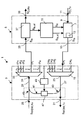
- the sole drawing shows a schematic block diagram of an optical WDM transmitting and receiving device according to the invention.
- the WDM transmitting and receiving device 1 shown in the single figure comprises an optical transceiver unit 3 and an optical filter unit 5.
- the optical transceiver unit 3 has an optical transmission unit 7, to which a data signal port 9 can supply an electrical data signal S D, Tx .
- the transceiver unit 3 can also have a data signal port 11 for this purpose.
- the optical transmission unit 7 comprises an optical transmission module 13, which is tunable with respect to its optical carrier wavelength. In the normal operating mode of operation, the optical transmission unit 7 converts the data signal S D, Tx supplied to it into a corresponding optical data signal.
- the optical transmitting unit can also perform a required Signalbe- or processing.
- a controller unit 15 of the transceiver unit 3 controls the transmitting unit 7 such that a signal having a predetermined optical carrier wavelength is output at an output port 17 of the transceiver unit 3.
- the controller unit 15 supplies the transmission unit 7 with a control signal S ⁇ i .
- the control signal is preferably such that only one channel information has to be transmitted to the transmitting unit in order to cause it to generate an optical transmission signal having a specific channel wavelength ⁇ i .
- the channel wavelength ⁇ i is one of n possible optical carrier wavelengths of optical signals, which are generated by a maximum of n transceiver units 3 and are each fed to a channel input port CH 1 to CH n of an optical multiplexer unit 19 of the optical filter unit 5.
- the output port of the transceiver unit 3 is supplied to the channel input port CH i of the multiplexer unit 19.
- further (maximum n) transceiver units may be connected to the remaining channel input ports CH 1 to CH ii and CH i + 1 to CH n .
- Each channel input port CH i of the multiplexer unit 19 is assigned a predetermined channel wavelength ⁇ i , each of the channel input ports CH 1 until CH n, only such optical signals are combined to form a WDM optical transmission signal S WDM, Tx , which have an optical carrier wavelength tuned to the respective channel wavelength ⁇ i .
- This WDM optical transmission signal S WDM, TX is supplied to the multiplexer unit 19 via an WDM output port 25 and an optical path 27 to an optical output port 21 of the optical filter unit 5 and outputted thereto to an optical transmission path (not shown).
- a received WDM optical signal S WDM, RX a WDM input port 23 of the optical filter unit 5 can be fed.
- This WDM input port 23 is connected to a WDM input port 31 of a demultiplexer unit 33 via an optical path 29, so that the WDM received signal S WDM, Rx is also supplied to the WDM input port 31 of the demultiplexer unit 33.
- the demultiplexer unit 33 again has n channel output ports, which are designated in the figure by ch i to ch n .
- Each of the channel output ports ch i to ch n is in each case assigned the same channel wavelength ⁇ 1 to ⁇ n as the respective channel input port CH 1 to CH n .
- the channel output port CH i is connected to an input port 35 of the transceiver unit 3, which in turn is connected to an input port of a receiving unit 37 which is included in the optical transceiver unit 3.
- the WDM received signal S WDM, Rx supplied to the WDM input port 23 from the connected transmission link (not shown) is supplied to the WDM input port 31 of the demultiplexer unit 33.
- the demultiplexer unit 33 demultiplexes the WDM received optical signal S WDM, Rx into the individual channel signals supplied respectively to the channel output port ch 1 to ch n having the respective channel wavelength ⁇ 1 .
- the channel signal having the channel wavelength ⁇ i is supplied to the input port 35 of the transceiver unit 3 and thus to the receiving unit 37.
- the receiving unit 37 converts the optical Channel signal in an electrical data signal S D, Rx and outputs this on a data signal port 39 of the transceiver unit 3 from.
- the controller unit 15 For correct operation of the transceiver unit 3 on the filter unit 5, it is thus necessary for the controller unit 15 to control the optical transmission unit 7 in such a way that the optical signal supplied to the respective channel input port CH i has the channel wavelength ⁇ i assigned to this port. Otherwise, the optical signal would be blocked by the multiplexer unit 19 and can not be integrated into the WDM transmit signal S WDM, Tx .
- the controller unit 15 When a transceiver unit 3 is newly connected to the optical filter unit 5, the controller unit 15 performs the functions explained below in a tuning mode.
- the tuning mode can be triggered manually or by a higher-level control unit by supplying a corresponding drive signal S T.
- the controller unit 15 must either be aware in advance of which discrete wavelengths are used by the WDM system or the WDM transceiver 1, in which the transceiver unit 3 is to be integrated. For a complete continuous tuning of the optical transmitter module would be too time consuming.
- the discrete channel wavelengths can be stored in the controller unit 15 from the outset. Of course, however, it is also possible for the controller unit 15 to supply this information via a suitable interface (not shown) from a higher-level unit.
- the controller unit 15 After the controller unit 15 has been set to the tuning mode, it first supplies the optical transmission unit 7 with a signal S ⁇ i , thereby setting a first of the possible channel wavelengths . That is, as a result of the signal S ⁇ i supplied to it , the transmitting unit 7 generates a tuning signal S ts which has the relevant channel wavelength ⁇ i .
- the tuning signal S ts can be generated in various ways: On the one hand, it is possible to use an already applied data signal S D, Tx and to convert this into a corresponding optical signal, which is then used as the tuning signal S ts . It is also possible to ignore the data signal S D, Tx and instead to turn it on to generate special, independent tuning signal.
- the controller unit 15 of the control unit 7, a corresponding electrical tuning signal S ts, el perform.
- This special tuning signal S ts, el can for example be formed as a low-frequency signal with a fixed frequency (whether sinusoidal or rectangular or with another periodic structure).
- the optical tuning signal S ts which is output at the output port 17 of the transceiver unit 3, have a corresponding time characteristic, wherein the optical carrier wavelength is determined by the signal S ⁇ l , with which the controller unit 15 controls the transmitting unit 7 ,
- the optical signal S ts, el which is a relatively low-frequency signal, can be used as a modulation signal for the high bit-rate data signal S D, Tx .
- the tuning signal S ts is not transmitted to the WDM output port 25 via the multiplexer unit 19.
- the receiving unit 37 no optical tuning received signal E ts can be detected, which could be supplied to the controller unit 15 as an optical tuning received signal E ts, el .
- the controller unit 15 controls the optical transmitting unit 7 so that a different channel wavelength; is set. This stepwise scanning is continued until the controller unit 15 detects a tuning received signal E ts , el which is supplied thereto from the optical receiving unit 37.
- the optical Receiving unit 37 is formed so that each of the selectable channel wavelengths is detectable.
- the controller unit 15 is supplied with a tuning received signal E ts, el , this fact can already be used by the controller unit 15 as a termination criterion for the loop to be passed in the tuning mode, since the controller unit 15 is in this simplest If the presence of a detected signal E ts, el with arbitrary properties can already be an indication that a signal has been transmitted via the loop-back path 41 and, consequently, the transmitting unit 7 is operating at the correct transmission wavelength or channel wavelength. Decisive in this case is only a certain minimum level for the received power of the optical signal E ts .
- the controller unit 15 preferably detects whether the tuning received signal E ts, el has a characteristic property known to it.
- the controller unit 15 can control the transmitting unit 7 in such a way that a specific special tuning signal S ts is generated which, for example, has a specific (low) fundamental frequency. If the controller unit 15 detects the same characteristic property in the tuning reception signal E ts, el supplied to it, it can be assumed with relatively high certainty that this received signal was generated by the transmission signal S ts , which is transmitted via the loop-back path 41 the receiving unit 37 has been supplied.
- the controller unit 15 detects the same characteristic property in the tuning reception signal E ts, el supplied to it, it can be assumed with relatively high certainty that this received signal was generated by the transmission signal S ts , which is transmitted via the loop-back path 41 the receiving unit 37 has been supplied.
- there are a number of different possibilities for generating corresponding characteristic properties of the tuning signal S ts which will be considered by a person skilled in the art, such as the abovementioned possibility of amplitude modulation. Further possibilities are frequency- or phase-modulated signals with certain characteristic properties
- a tuning received signal E ts el as a correct "receive signal" which can be generated, for example, by another transceiver unit 3 located in a tuning mode at the other end of the link (even if this case very unlikely)
- this signal includes the information of a unique serial number or MAC address of the transceiver unit 3 concerned. For example, if there are five digit unique serial numbers, then 10 5 different values suffice for one or more particular characteristics (or parameters) of the tuning signal. For example, 10 5 different frequency values for the amplitude modulation can be selected.
- the controller unit 15 can then not only detect that a signal is detected at a correctly selected channel wavelength ⁇ i , but also check whether the detected signal has the identifier known to it, namely the modulation frequency corresponding to the serial number.
- the respective modulation frequency can also be detected.
- the controller unit 15 can then regard the termination criterion for the tuning loop as fulfilled only if the tuning received signal E ts, el has the correct frequency corresponding to the serial number.
- the reception level for the signal E ts , el can also be checked for plausibility.
- the controller unit 15 can detect whether the reception level for the reception signal E ts is greater than a predetermined barrier. Because with an extremely sensitive detection of the received signal theoretically, a signal could be detected, which is generated by a channel signal with the wrong wavelength, wherein a corresponding received signal were generated by finite values for the crosstalk attenuation of the multiplexer unit or demultiplexer unit 19, 33.
- the security can therefore be increased if the controller unit 15 considers the termination criterion satisfied only if the tuning received signal E ts exceeds a certain reception level.
- the Controller unit 15 In order to additionally rule out that from the other end of the transmission line forth a signal is received which coincidentally has the same characteristics (of the time course) as the currently sent by the transmitting unit 7 signal S ts (but has the wrong channel wavelength), the Controller unit 15 additionally check whether the received signal S ts (or the corresponding electrical received signal E ts, el ) does not exceed a predetermined maximum level. This is determined by the predetermined insertion loss of the optical path between the output port 17 and the input port 35 of the transceiver unit 3 via the path which is defined by the loop-back path 41.
- the controller unit 15 as a characteristic properties of the received signal E ts next to its time course and the level of the received signal then check whether this is within a permissible range.
- a modulator unit 47 can be provided, which can be controlled by a control unit 49 of the filter unit 5.
- the modulator unit 49 may, as in Fig. 1 represented by the double arrow, also be connected to a higher-level control unit.
- the control unit 49 can thus impose additional information on the signal which is fed via the loop-back path 41. This information can also be received by the controller unit 15.
- These may be certain properties or characteristics of the filter unit, such as the serial number, the channel number, the carrier wavelengths of the channels, and the like.
- the controller unit 15 detects the abort criterion as fulfilled, then the tuning mode is ended. If the abort criterion is not detected in any of the individual steps of the tuning mode, for example because the input port 35 of the transceiver unit 3 is detected is not connected to the correct channel output port ch 1 to ch n , an error signal can be generated.
- Such a WDM transmitting and receiving device or such an optical transceiver unit allows the automatic setting of the correct channel wavelength, without the need for a significant intervention of an operator would be required (apart from the possibly required start of the tuning mode). This drastically reduces the possibility of errors during the commissioning of such a transceiver unit.
Landscapes
- Engineering & Computer Science (AREA)
- Computer Networks & Wireless Communication (AREA)
- Signal Processing (AREA)
- Optical Communication System (AREA)
Abstract
Description
Die Erfindung betrifft eine optische Transceivereinheit für eine optische WDM Sende- und Empfangseinrichtung mit den Merkmalen des Oberbegriffs des Patentanspruchs 1. Des Weiteren betrifft die Erfindung eine optische WDM Sende- und Empfangseinrichtung mit einer derartigen optischen WDM-Transceivereinheit.The invention relates to an optical transceiver unit for an optical WDM transmitting and receiving device having the features of the preamble of patent claim 1. Furthermore, the invention relates to an optical WDM transmitting and receiving device with such a WDM optical transceiver unit.
In optischen Übertragungsnetzen finden zur Übertragung großer Datenvolumen optische Wellenlängenmultiplex-Systeme (WDM-Systeme) Verwendung. In einem Netzknoten oder einem Terminal-Knoten einer einfachen Punkt-zu-Punkt Verbindung ist dabei jeweils eine optische Filtereinheit vorgesehen, welche zumindest eine optische Multiplexereinheit und eine optische Demultiplexereinheit umfasst. Die optische Multiplexereinheit weist eine vorbestimmte Anzahl n von Kanal-Eingangsports auf, und führt den Kanal- Eingangsports zugeführte optische Kanalsignale einem WDM-Ausgangsport zu, wobei die optischen Kanalsignale zu einem WDM-Signal kombiniert werden. Die optische Demultiplexereinheit weist einen WDM-Eingangsport auf, welchem das zu empfangende WDM-Signal zugeführt ist. Die Multiplexereinheit splittet das optische WDM-Empfangssignal in die einzelnen Kanalsignale auf und führt diese jeweils einem zugeordneten Kanal-Ausgangsport zu. Jedem Kanal-Eingangsport der Multiplexereinheit kann ein optisches Kanalsignal einer vorbestimmten optischen Trägerwellenlänge zugeführt werden, wobei die jeweilige optische Trägerwellenlänge des zugeführten optischen Signals der dem betreffenden Kanal-Eingangsport zugeordneten Kanalwellenlänge entsprechen muss, damit das betreffende optische Kanalsignal korrekt und mit möglichst geringer Einfügedämpfung dem WDM-Ausgangsport zugeführt werden kann.In optical transmission networks, optical wavelength division multiplexing (WDM) systems are used to transmit large volumes of data. An optical filter unit, which comprises at least one optical multiplexer unit and one optical demultiplexer unit, is provided in each case in a network node or a terminal node of a simple point-to-point connection. The optical multiplexer unit has a predetermined number n of channel input ports, and supplies optical channel signals supplied to the channel input ports to a WDM output port, the optical channel signals being combined into a WDM signal. The optical demultiplexer unit has a WDM input port to which the WDM signal to be received is supplied. The multiplexer unit splits the optical WDM receive signal into the individual channel signals and feeds them each to an associated channel output port. Each channel input port of the multiplexer unit, an optical channel signal of a predetermined optical carrier wavelength can be supplied, the respective optical carrier wavelength of the supplied optical signal must correspond to the relevant channel input port channel wavelength, so that the respective optical channel signal correctly and with the lowest possible insertion loss to the WDM Output port can be supplied.
In gleicher Weise kann ein in einem empfangenen optischen WDM-Signal enthaltenes Kanalsignal einer vorbestimmten optischen Trägerwellenlänge, die einer Kanalwellenlänge entsprechen muss, von der Demultiplexereinheit aus dem WDM-Empfangssignal extrahiert und dem zugeordneten Kanal-Ausgangsport zugeführt werden. Die Kanalwellenlängen für die Senderichtung und für die Empfangsrichtung sind dabei jeweils so gewählt, dass für einen Kanal i sowohl für die Senderichtung als auch für die Empfangsrichtung die selbe optische Kanalwellenlänge verwendet wird.Likewise, a channel signal of a predetermined optical carrier wavelength which is to be a channel wavelength included in a received WDM optical signal may be extracted from the WDM received signal by the demultiplexer unit and supplied to the associated channel output port. The channel wavelengths for the transmission direction and for the reception direction are in each case selected such that the same optical channel wavelength is used for a channel i both for the transmission direction and for the reception direction.
Übliche optische Filtereinheiten weisen dabei meist eine Vielzahl, beispielsweise 40, Kanal-Eingangsports bzw. Kanal-Ausgangsports auf. Um eine bidirektionale Verbindung auf einem vorbestimmten Kanal zu ermöglichen, wird jeweils eine optische Transceivereinheit verwendet, die aus einem ihr zugeführten elektrischen Datensignal ein entsprechendes optisches Datensignal erzeugt, welches an einem optischen Ausgangsport der Transceivereinheit abgegeben wird. Dieser optische Ausgangsport der Transceivereinheit wird über einen Lichtwellenleiter mit dem zugehörigen Kanal-Eingangsport der Multiplexereinheit der optischen Filtereinheit verbunden. Hierzu muss selbstverständlich derjenige Kanal-Eingangsport der Multiplexereinheit gewählt werden, der hinsichtlich der Kanalwellenlänge der optischen Trägerwellenlänge des von der Transceivereinheit abgegebenen optischen Signals entspricht oder, mit anderen Worten, die Trägerwellenlänge des von der Transceivereinheit abgegebenen optischen Signals muss der Kanalwellenlänge des gewählten Kanal-Eingangsports der Multiplexereinheit entsprechen.Conventional optical filter units usually have a multiplicity, for example 40, channel input ports or channel output ports. In order to enable a bidirectional connection on a predetermined channel, an optical transceiver unit is used in each case, which generates from a supplied electrical data signal, a corresponding optical data signal which is delivered to an optical output port of the transceiver unit. This optical output port of the transceiver unit is connected via an optical waveguide with the associated channel input port of the multiplexer unit of the optical filter unit. Of course, for this purpose, one channel input port of the multiplexer unit must be selected, which corresponds in terms of channel wavelength to the optical carrier wavelength of the optical signal emitted by the transceiver unit or, in other words, the carrier wavelength of the optical signal output by the transceiver unit must be the channel wavelength of the selected channel input port correspond to the multiplexer unit.
In gleicher Weise wird der zugehörige Kanal-Ausgangsport der Demultiplexereinheit, welcher die betreffende Kanalwellenlänge zugeordnet ist, mit einem Eingangsport der optischen Transceivereinheit verbunden, welcher in der Transceivereinheit das empfangene Kanalsignal einer Empfangseinheit der Transceivereinheit zuführt, die üblicherweise so breitbandig ausgebildet ist, dass sie in der Lage ist, jedes der möglichen Kanalsignale zu detektieren. Die Empfangseinheit setzt das optische Kanalsignal in ein entsprechendes elektrisches Datensignal um und kann gleichzeitig eine Signalaufbereitung und ggf. auch eine Signalverarbeitung vornehmen.In the same way, the associated channel output port of the demultiplexer unit, which is associated with the relevant channel wavelength, connected to an input port of the optical transceiver unit, which supplies in the transceiver unit, the received channel signal of a receiving unit of the transceiver unit, which is usually formed broadband so that in capable of detecting any of the possible channel signals. The receiving unit converts the optical channel signal into a corresponding electrical data signal and can at the same time carry out a signal processing and possibly also a signal processing.
Derartige optische Transceivereinheiten wurden üblicherweise mit Sendeeinheiten versehen, welche ein optisches Sendemodul der gewünschten Kanalwellenlänge aufweist. Es war daher erforderlich, für jede Kanalwellenlänge eine optische Transceivereinheit mit der gewünschten (festen) Kanalwellenlänge vorzusehen.Such optical transceiver units have conventionally been provided with transmission units which have an optical transmission module of the desired channel wavelength. It was therefore necessary to provide for each channel wavelength an optical transceiver unit with the desired (fixed) channel wavelength.
In jüngerer Zeit wurden optische Transceivereinheiten mit durchstimmbaren Sendemodulen entwickelt. Bei derartigen Transceivereinheiten kann die das betreffende Sendemodul umfassende Sendeeinheit von einer Controllereinheit so angesteuert werden, dass aus dem der Transceivereinheit zugeführten elektrischen Datensignal ein optisches Sendesignal mit der gewünschten Kanalwellenlänge erzeugt wird. Die Controllereinheit führt der Sendeeinheit dabei üblicherweise nur eine Kanalinformation zu, d.h. es wird festgelegt, welche von mehreren möglichen diskreten Kanalwellenlängen für das zu erzeugende optische Sendesignal verwendet werden soll.More recently, transceiver optical units have been developed with tunable transmitter modules. In such transceiver units, the transmission unit comprising the respective transmission module can be controlled by a controller unit such that an optical transmission signal having the desired channel wavelength is generated from the electrical data signal supplied to the transceiver unit. The controller unit leads the transmitting unit usually only one channel information to, ie it is determined which of several possible discrete channel wavelengths to be used for the optical transmission signal to be generated.
Mit derartigen durchstimmbaren Transceivereinheiten ist es möglich, eine Transceivereinheit zunächst mit einem beliebigen freien Kanal-Eingangsport der Multiplexereinheit einer optischen Filtereinheit zu verbinden. Selbstverständlich muss die Empfangseinheit der Transceivereinheit dabei mit den zugeordneten Kanal-Ausgangsport der Demultiplexereinheit verbunden werden, welchem die selbe Kanalwellenlänge zugeordnet ist. Bei bekannten Transceivermodulen wird der optischen Sendeeinheit dann die Information zugeführt, welche Kanalwellenlänge für das optische Sendesignal verwendet werden soll.With such tunable transceiver units, it is possible to first connect a transceiver unit to any free channel input port of the multiplexer unit of an optical filter unit. Of course, the receiving unit of the transceiver unit must be connected to the associated channel output port of the demultiplexer, which is assigned the same channel wavelength. In known transceiver modules, the optical transmission unit is then supplied with the information which channel wavelength is to be used for the optical transmission signal.
Hierbei besteht jedoch das Risiko, dass die Controllereinheit der optischen Sendeeinheit nicht die korrekte Information betreffend die zu wählende Kanalwellenlänge übermittelt wird, beispielsweise weil bei der Installation der Transceivereinheit die diese Installation vornehmende Person der Controllereinheit die falsche Information übermittelt hat. Neben diesem Risiko einer nicht korrekten Installation der Transceivereinheit, beispielsweise an einem bestehenden WDM-System wird durch die Notwendigkeit der korrekten Wahl der Kanalwellenlänge bei einer durchstimmbaren optischen Transceivereinheit auch ein entsprechender Aufwand verursacht. Denn diejenige Person, die einen Austausch einer Transceiverkarte vornimmt oder das bestehende System durch das hinzufügen einer oder mehrerer weiterer Transceiverkarten erweitert, muss sich vor der Installation darüber informieren, welche Kanalwellenlängen bereits belegt sind und welche Kanalwellenlängen des Systems noch zur Verfügung stehen bzw. auf welcher Kanalwellenlänge die zu ersetzende Transceivereinheit gesendet hat.In this case, however, there is the risk that the controller unit of the optical transmission unit is not transmitted the correct information regarding the channel wavelength to be selected, for example, because during the installation of the transceiver unit, the person performing this installation has transmitted the wrong information to the controller unit. In addition to this risk of improper installation of the transceiver unit, for example on an existing WDM system, the necessity of correctly selecting the channel wavelength for a tunable optical transceiver unit also causes a corresponding expense. Because the person who makes a replacement of a transceiver card or extends the existing system by adding one or more additional transceiver cards, must be informed prior to installation, which channel wavelengths are already occupied and which channel wavelengths of the system are still available or on which Channel wavelength has sent the transceiver unit to be replaced.
Wird die Kanalwellenlänge einer durchstimmbaren optischen Transceivereinheit nicht korrekt gewählt, so kann die Multiplexereinheit selbstverständlich das einem Kanal-Eingangsport zugeführte optische Signal, das nicht die korrekte Kanalwellenlänge aufweist, nicht in das zu sendende WDM-Signal integrieren.Of course, if the channel wavelength of a tunable optical transceiver unit is not chosen correctly, the multiplexer unit can not integrate the optical signal supplied to a channel input port which does not have the correct channel wavelength into the WDM signal to be transmitted.
Der Erfindung liegt daher die Aufgabe zugrunde, eine optische Transceivereinheit für eine optische WDM Sende- und Empfangseinrichtung zu schaffen, welche einen möglichst einfachen Anschluss der Transceivereinheit an eine Filtereinheit der optischen WDM Sende-und Empfangseinrichtung ermöglicht, wobei auch das Risiko einer fehlerhaften Einstellung der Kanalwellenlänge reduziert bzw. vermieden wird.The invention is therefore based on the object to provide an optical transceiver unit for an optical WDM transmitting and receiving device, which as simple as possible connection of the transceiver unit to a filter unit of the optical WDM transmitting and Receiving device allows, whereby the risk of incorrect adjustment of the channel wavelength is reduced or avoided.
Die Erfindung löst diese Aufgabe mit den Merkmalen des Patentanspruchs 1. Der Patentanspruch 11 schafft mit seiner Merkmalskombination eine optische WDM Sende- und Empfangseinrichtung mit einer derart ausgebildeten Transceivereinheit.The invention solves this problem with the features of patent claim 1. The
Die Erfindung geht von der Erkenntnis aus, dass im Fall einer durchstimmbaren optischen Transceivereinheit eine selbsttätige Einstellung der korrekten optischen Trägerwellenlänge des von der Transceivereinheit zu erzeugenden Kanalsignals erfolgen kann, wenn die Controllereinheit so ausgebildet ist, dass diese in einem Tuning-Modus das ihr von der Empfängereinheit zugeführte Empfangssignal auswertet und abhängig hiervon die Entscheidung trifft, welche Kanalwellenlänge die jeweils korrekte ist. Hierzu steuert die Controllereinheit die Sendeeinheit im Tuning-Modus zunächst so an, dass eine erste der möglichen Kanalwellenlängen für ein zu erzeugendes Tuning-Sendesignal verwendet wird. Dieses Sendesignal wird der Multiplexereinheit am betreffenden Kanal-Eingangsport zugeführt.The invention is based on the recognition that, in the case of a tunable optical transceiver unit, an automatic adjustment of the correct optical carrier wavelength of the channel signal to be generated by the transceiver unit can take place if the controller unit is designed in a tuning mode that matches that of the Receiver unit evaluates the received signal supplied and, depending on this, the decision is made, which channel wavelength is the correct one. For this purpose, the controller unit first controls the transmitting unit in the tuning mode in such a way that a first of the possible channel wavelengths is used for a tuning transmission signal to be generated. This transmission signal is supplied to the multiplexer unit at the respective channel input port.
Eine erfindungsgemäße optische WDM Sende- und Empfangseinrichtung weist einen optischen Verbindungspfad zwischen dem WDM-Ausgangsport der Multiplexereinheit und dem WDM-Eingangsport der Demultiplexereinheit auf. Hierzu wird, beispielsweise mittels eines breitbandigen 1x2-Kopplers ein geringer Teil der optischen Leistung des WDM-Sendesignals ausgekoppelt und mittels eines weiteren 1 x2-Kopplers dem optischen Empfangspfad in Richtung auf den WDM-Eingangsport der Demultiplexereinheit zugeführt. Mittels dieses Loop-Back-Pfads ist es der erfindungsgemäßen optischen Transceivereinheit möglich, festzustellen, ob das gesendete Kanalsignal mit der jeweils aktuellen optischen Trägerwellenlänge (Kanalwellenlänge) tatsächlich auch am Ausgangsport der Multiplexereinheit vorhanden ist, was nur dann der Fall sein kann, wenn die Kanalwellenlänge für denbetreffenden Kanal-Eingangsport der Multiplexereinheit korrekt gewählt wurde.An inventive optical WDM transmitting and receiving device has an optical connection path between the WDM output port of the multiplexer unit and the WDM input port of the demultiplexer unit. For this purpose, for example by means of a broadband 1x2 coupler, a small part of the optical power of the WDM transmission signal is coupled out and fed to the optical reception path in the direction of the WDM input port of the demultiplexer unit by means of a further 1 × 2 coupler. By means of this loop-back path it is possible for the optical transceiver unit according to the invention to determine whether the transmitted channel signal with the respective current optical carrier wavelength (channel wavelength) is actually present at the output port of the multiplexer unit, which can only be the case if the channel wavelength was correctly selected for the relevant channel input port of the multiplexer unit.
Hierzu detektiert die Empfangseinheit der Transceivereinheit im Tuning-Modus und führt das in ein elektrisches Signal umgesetzte Empfangssignal der Controllereinheit zu. Die Controllereinheit verwendet ein Abbruchkriterium (welches auch mehrere Teilkriterien bzw. mehrere notwendige Voraussetzungen für das positive Bejahen des Abbruchkriteriums umfassen kann), um den Tuning-Modus nach dem Erreichen des Einstellens der korrekten Kanalwellenlänge beenden zu können.For this purpose, the receiving unit of the transceiver unit detects in the tuning mode and supplies the received signal converted into an electrical signal to the controller unit. The controller unit uses an abort criterion (which also includes several subcriteria or several necessary prerequisites for the positive affirmation of the abort criterion may include) to finish the tuning mode after reaching the correct channel wavelength setting.
Wird davon ausgegangen, dass an denjenigen Kanal-Ausgangsport der Demultiplexereinheit normalerweise kein Signal anliegen kann, wenn dieser Port vor dem Hinzufügen der Transceivereinheit unbeschaltet war, so kann das einfachste Abbruchkriterium darin bestehen, dass überhaupt eine optische Leistung an diesem Port detektiert wird. In diesem Fall wird die Controllereinheit den Tuning-Modus beenden, sobald ihr von der Empfangseinheit ein optisches Signal (mit ausreichender Leistung) zugeführt wird.If it is assumed that no signal can normally be present at the channel output port of the demultiplexer unit if this port was not connected before the addition of the transceiver unit, then the simplest termination criterion may be that an optical power is actually detected at this port. In this case, the controller unit will terminate the tuning mode as soon as it receives an optical signal (with sufficient power) from the receiving unit.
Ist das Abbruchkriterium nicht erfüllt, so steuert die Controllereinheit die optische Sendeeinheit der Transceivereinheit so an, dass eine weitere der möglichen Kanalwellenlängen für das zu erzeugende Tuning-Signal verwendet wird. Auch in diesem weiteren Schritt des Tuning-Modus wird wiederum detektiert, ob das Abbruchkriterium erfüllt ist. So werden erforderlichenfalls sämtliche zur Verfügung stehende Kanalwellenlängen nacheinander für das Erzeugen jeweils eines entsprechenden Tuning-Sendesignals verwendet, wobei das vorgegebene Abbruchkriterium in jedem Tuning-Schritt geprüft wird. Ist das Abbruchkriterium erfüllt, so wird der Tuning-Modus beendet und die Transceivereinheit kann zum normalen Sendebetrieb übergehen.If the termination criterion is not met, the controller unit controls the optical transmission unit of the transceiver unit in such a way that a further of the possible channel wavelengths is used for the tuning signal to be generated. In this further step of the tuning mode, it is again detected whether the termination criterion has been met. Thus, if necessary, all available channel wavelengths are successively used for generating a corresponding tuning transmission signal, wherein the predetermined termination criterion is checked in each tuning step. If the abort criterion is met, the tuning mode is terminated and the transceiver unit can proceed to normal transmission mode.
Als Tuning-Signal kann auch ein der Sendeeinheit der Transceivereinheit zugeführtes Datensignal verwendet werden, wobei im Tuning-Modus selbstverständlich keine korrekte bidirektionale Kommunikation möglich ist.As a tuning signal also a transmission unit of the transceiver unit supplied data signal can be used, in the tuning mode, of course, no correct bidirectional communication is possible.
Nach einer Ausgestaltung der Erfindung kann die optische Sendeeinheit dem ihr zugeführten Datensignal auch eine charakteristische Eigenschaft aufprägen, wobei hierzu die Sendeeinheit in geeigneter Weise von der Controllereinheit angesteuert wird.According to one embodiment of the invention, the optical transmission unit can also impart a characteristic property to the data signal supplied to it, for which purpose the transmission unit is controlled in a suitable manner by the controller unit.
Nach einer anderen Ausgestaltung der Erfindung kann das Tuning-Sendesignal auch unabhängig von einem der Sendeeinheit zugeführten Datensignal erzeugt werden, wobei hierzu die Controllereinheit der Sendeeinheit ein geeignetes elektrisches Tuning-Sendesignal zuführen kann. Dieses Kennungssignal kann selbstverständlich ebenfalls vorgegebene charakteristische Eigenschaften aufweisen.According to another embodiment of the invention, the tuning transmission signal can also be generated independently of a data signal supplied to the transmission unit, for which purpose the controller unit of the transmission unit can supply a suitable electrical tuning transmission signal. Of course, this identification signal can also have predetermined characteristic properties.
Nach einer Ausführungsform der Erfindung kann die charakteristische Eigenschaft des Kennungssignals oder die wenigstens eine dem Datensignal aufgeprägte charakteristische Eigenschaft ein bestimmter Parameter einer Modulationskomponente sein, vorzugsweise eine vorgegebene Modulationsfrequenz einer Amplitudenmodulation.According to one embodiment of the invention, the characteristic property of the identification signal or the at least one characteristic property impressed on the data signal may be a specific parameter of a modulation component, preferably a predetermined modulation frequency of an amplitude modulation.
Beispielsweise kann die Controllereinheit die Sendeeinheit so ansteuern, dass ein hochbitratiges Datensignal relativ niederfrequent ein- und ausgeschaltet wird, wobei das Ein- und Ausschalten mit der vorbestimmten Frequenz erfolgt.For example, the controller unit can control the transmitting unit in such a way that a high-bit-rate data signal is switched on and off relatively low-frequency, the switching on and off taking place at the predetermined frequency.
Selbstverständlich kann die Controllereinheit anstelle der Modulation eines hochbitratigen Sendesignals der Sendeeinheit auch ein Kennungssignal zuführen, welches ein amplitudenmoduliertes Signal mit einer einzigen oder mehreren verschiedenen Modulationsfrequenzen ist, wobei im Fall mehrerer Modulationsfrequenzen diese nicht gleichzeitig sondern zeitlich nacheinander übertragen werden. Beispielsweise kann das Sendemodul der Sendeeinheit im CW-Betrieb relativ niederfrequent ein- und ausgeschaltet werden.Of course, instead of modulating a high-bit-rate transmission signal, the controller unit can also supply an identification signal, which is an amplitude-modulated signal having a single or several different modulation frequencies, in the case of several modulation frequencies not being transmitted simultaneously but temporally one after the other. For example, the transmission module of the transmitting unit in CW operation can be turned on and off relatively low frequency.
Selbstverständlich sind jedoch auch andere Modulationsweisen und Modulationsverfahren möglich. Beispielsweise kann auch eine sinusförmige Modulation des Datensignals oder eines CW-Signals mit einem bestimmten Modulationsgrad, der auch kleiner als 100% sein kann, vorgenommen werden. Darüber hinaus ist es auch denkbar, eine Frequenz oder Phasenmodulation zu verwenden, um dem Tuning-Signal jeweils vorgegebene charakteristische Eigenschaften aufzuprägen.Of course, however, other modes of modulation and modulation methods are possible. For example, a sinusoidal modulation of the data signal or a CW signal with a certain degree of modulation, which may also be less than 100%, be made. In addition, it is also conceivable to use a frequency or phase modulation in order to impose predetermined characteristic properties on the tuning signal.
Eine bestimmte charakteristische Eigenschaft, wie die Modulationsfrequenz einer Amplitudenmodulation, kann auch dazu verwendet werden, um eine der betreffenden Transceivereinheit eindeutig zugeordnete Kennung in das Tuning-Sendesignal zu integrieren. Selbstverständlich ist es ebenfalls möglich, nur einen Teil einer eindeutigen Kennung zu übertragen, auch wenn sich hierdurch eine reduzierte Sicherheit ergibt.A certain characteristic property, such as the modulation frequency of an amplitude modulation, can also be used to integrate an identifier uniquely assigned to the relevant transceiver unit into the tuning transmission signal. Of course, it is also possible to transmit only a part of a unique identifier, even if this results in a reduced security.
Die eindeutige Kennung kann beispielsweise in einer Seriennummer der Transceivereinheit oder in einer der Transceivereinheit zugeordneten Media-Access-Controll-Adresse bestehen.The unique identifier may consist, for example, in a serial number of the transceiver unit or in a media access controller address assigned to the transceiver unit.
Auf diese Weise ist es möglich, dass die Controllereinheit das ihr von der Empfangseinheit ggf. zugeführte optische Signal daraufhin überprüft, ob dieses Signal auch mit ausreichend hoher Sicherheit diejenigen charakteristischen Eigenschaften aufweist, die im jeweils gesendeten Tuning-Sendesignal enthalten sind.In this way, it is possible for the controller unit to check the optical signal possibly supplied to it by the receiving unit in order to determine whether this signal also has, with a sufficiently high degree of certainty, the characteristic properties which are contained in the respectively transmitted tuning transmission signal.
Besteht die charakteristische Eigenschaft in einer Amplitudenmodulation mit vorbestimmter Frequenz, so kann die Controllereinheit das ihr zugeführte Empfangssignal (bei korrekter Kanalwellenlänge) phasensensitiv detektieren, so dass das Abbruchkriterium nur dann als erfüllt angesehen werden kann, wenn die Controllereinheit (bzw. ein darin enthaltener Lockin Verstärker) ein Empfangssignal mit der jeweils vorbekannten Modulationsfrequenz detektiert.If the characteristic property exists in an amplitude modulation with a predetermined frequency, then the controller unit can detect the received signal supplied to it (with correct channel wavelength) in a phase-sensitive manner, so that the termination criterion can only be regarded as satisfied if the controller unit (or a lockin amplifier contained therein) ) detects a received signal with the respectively known modulation frequency.
Auf diese Weise ist es möglich zu unterscheiden, ob das detektierte Empfangssignal tatsächlich das gesendete Tuning-Signal ist, oder dieses zumindest umfasst. Andernfalls würde beispielsweise im Fall, dass auf dem gegenüberliegenden Ende der Übertragungsstrecke ein Signal mit der betreffenden Kanalwellenlänge gesendet wird, fälschlicherweise dieses von der Gegenseite der Übertragungsstrecke stammende Signal als Tuning-Empfangssignal erkannt und der Tuning-Modus abgebrochen, obwohl nicht die korrekte Kanalwellenlänge eingestellt wurde.In this way it is possible to distinguish whether the detected received signal is actually the transmitted tuning signal, or at least includes this. Otherwise, for example, in the case where a signal at the opposite channel length is transmitted on the opposite end of the transmission line, this signal originating from the opposite side of the transmission line would be erroneously recognized as the tuning received signal and the tuning mode aborted, even though the correct channel wavelength was not set ,
Neben einer Störung von der Gegenseite der Übertragungsstrecke (diese kann sowohl in Form eines Datensignals als auch in Form eines auf der Gegenseite verwendeten Tuning-Signals bestehen) kann auch eine Störung dadurch erfolgen, dass auf der jeweils selben Seite der Übertragungsstrecke noch eine weitere Transceivereinheit im Tuning-Modus arbeitet.In addition to a fault from the opposite side of the transmission path (this may consist both in the form of a data signal and in the form of a used on the opposite side tuning signal) can also be a disturbance characterized in that on the same side of the transmission line yet another transceiver unit in Tuning mode works.
Um die Sicherheit noch weiter zu erhöhen, dass tatsächlich das jeweils von der betreffenden Transceivereinheit gesendete Tuning-Signal detektiert wurde, kann die Controllereinheit den Dämpfungswert zwischen dem detektierten Empfangssignal und dem optischen Tuning-Sendesignal ermitteln und das Abbruchkriterium zusätzlich nur dann als erfüllt ansehen, wenn der Dämpfungswert kleiner als ein vorgegebener Maximalwert ist, bei dessen Ermittlung insbesondere die Nebensprechdämpfungen der Multiplexereinheit und der Demultiplexereinheit der WDM Sende-und Empfangseinrichtung berücksichtigt werden sowie die Dämpfung des optischen Pfades, den das Tuning-Sendesignal bis zum Empfang durch die Empfangseinheit durchläuft.In order to further increase the certainty that the respective tuning signal transmitted by the respective transceiver unit has actually been detected, the controller unit can determine the attenuation value between the detected received signal and the optical tuning transmission signal and additionally consider the abort criterion to be satisfied only if the attenuation value is smaller than a predefined maximum value, in the determination of which, in particular, the crosstalk attenuations of the multiplexer unit and of the demultiplexer unit of the WDM transmitting and receiving device are taken into account, and the attenuation of the optical path through which the tuning transmission signal passes until receipt by the receiving unit.
Anderenfalls bestünde die Gefahr, dass auch ein Empfangssignal, welches lediglich durch Nebensprechen in der Multiplexer- bzw. Demultiplexereinheit erzeugt wurde, als korrektes Empfangssignal detektiert wird. Diese weitere Sicherheitsmaßnahme empfiehlt sich insbesondere dann, wenn eine hochempfindliche Detektion des Empfangssignals vorgenommen wird, beispielsweise mittels einer phasensensitiven Gleichrichtung.Otherwise, there would be a risk that a received signal, which was generated only by cross-talk in the multiplexer or demultiplexer unit, is detected as a correct received signal. This further safety measure is particularly recommended when a highly sensitive detection of the received signal is made, for example by means of a phase-sensitive rectification.
In gleicher Weise kann die Controllereinheit auch den Dämpfungswert zwischen dem detektierten Empfangssignal und dem optischen Tuning-Sendesignal ermitteln und das Abbruchkriterium zusätzlich nur dann als erfüllt ansehen, wenn der Dämpfungswert größer als ein vorgegebener Maximalwert ist, bei dessen Ermittlung insbesondere die Einfügedämpfungen der Multiplexereinheit und der Demultiplexereinheit der WDM Sende- und Empfangseinrichtung berücksichtigt werden sowie die Dämpfung des optischen Pfades, den das Tuning-Sendesignal bis zum Empfang durch die Empfangseinheit durchläuft.In the same way, the controller unit can also determine the attenuation value between the detected received signal and the optical tuning transmission signal and additionally consider the abort criterion as fulfilled only if the attenuation value is greater than a predefined maximum value, in the determination of which the insertion attenuations of the multiplexer unit and the Demux unit of the WDM transmitting and receiving device are taken into account as well as the attenuation of the optical path, which passes through the tuning transmission signal to the reception by the receiving unit.
Hierdurch kann vermieden werden, dass ein Empfangssignal als korrektes Tuning-Empfangssignal erkannt wird, wobei dieses (mit der korrekten Kanalwellenlänge) zufälligerweise von einer anderen Transceivereinheit auf der selben Seite oder der gegenüberliegenden Seite der Übertragungsstrecke erzeugt wurde, wobei das von der "eigenen" Sendeeinheit erzeugte Kanalsignal noch auf einer "falschen" Wellenlänge liegt.In this way it can be avoided that a received signal is recognized as a correct tuning received signal, this (with the correct channel wavelength) was randomly generated by another transceiver unit on the same side or the opposite side of the transmission line, which of the "own" transmitting unit generated channel signal is still on a "wrong" wavelength.
Nach einer weiteren Ausgestaltung der Erfindung kann im Loop-Back-Pfad der optischen WDM Sende-und Empfangseinrichtung eine optische Modulatoreinheit vorgesehen sein, welche von einer Steuereinheit der Filtereinheit ansteuerbar ist. Auf diese Weise kann dem Tuning-Signal eine zusätzliche Information aufgeprägt werden. Hierdurch lassen sich beispielsweise bestimmte Parameter der Filtereinheit an die jeweilige Transceivereinheit übermitteln, wie beispielsweise Kenndaten der Multiplexereinheit, der Demultiplexereinheit, der Steuereinheit, eine Seriennummer, die Kanalanzahl und dergleichen.According to a further embodiment of the invention, an optical modulator unit can be provided in the loop-back path of the optical WDM transmitting and receiving device, which can be controlled by a control unit of the filter unit. In this way, additional information can be impressed on the tuning signal. In this way, for example, certain parameters of the filter unit can be transmitted to the respective transceiver unit, such as characteristics of the multiplexer unit, the demultiplexer unit, the control unit, a serial number, the number of channels and the like.
Weitere Ausführungsformen der Erfindung ergeben sich aus den Unteransprüchen. Die Erfindung wird nachstehend anhand eines in der Zeichnung dargestellten Ausführungsbeispiels näher erläutert.Further embodiments of the invention will become apparent from the dependent claims. The invention will be explained in more detail with reference to an embodiment shown in the drawing.
Die einzige Zeichnung zeigt ein schematisches Blockdiagramm einer optischen WDM Sende-und Empfangseinrichtung nach der Erfindung.The sole drawing shows a schematic block diagram of an optical WDM transmitting and receiving device according to the invention.
Die in der einzigen Fig. dargestellte WDM Sende-und Empfangseinrichtung 1 umfasst eine optische Transceivereinheit 3 und eine optische Filtereinheit 5.The WDM transmitting and receiving device 1 shown in the single figure comprises an
Die optische Transceivereinheit 3 weist eine optische Sendeeinheit 7 auf, welcher über einen Datensignalport 9 ein elektrisches Datensignal SD, Tx zuführbar ist. Hierzu kann selbstverständlich auch die Transceivereinheit 3 einen Datensignalport 11 aufweisen. Die optische Sendeeinheit 7 umfasst ein optisches Sendemodul 13, welches hinsichtlich seiner optischen Trägerwellenlänge durchstimmbar ist. Im normalen Arbeitsbetriebsmodus setzt die optische Sendeeinheit 7 das ihr zugeführte Datensignal SD, Tx in ein entsprechendes optisches Datensignal um. Selbstverständlich kann die optische Sendeeinheit auch eine erforderliche Signalbe- oder verarbeitung durchführen.The
Eine Controllereinheit 15 der Transceivereinheit 3 steuert hierzu die Sendeeinheit 7 so an, dass an einem Ausgangsport 17 der Transceivereinheit 3 ein Signal mit einer vorbestimmten optischen Trägerwellenlänge abgegeben wird. Hierzu führt die Controllereinheit 15 der Sendeeinheit 7 ein Steuersignal Sλi zu. Das Steuersignal ist dabei vorzugsweise so beschaffen, dass der Sendeeinheit nur eine Kanalinformation übermittelt werden muss, um diese zu veranlassen, ein optisches Sendesignal mit einer bestimmten Kanalwellenlänge λi zu erzeugen.For this purpose, a
Die Kanalwellenlänge λi ist dabei eine von n möglichen optischen Trägerwellenlängen von optischen Signalen, die von maximal n Transceivereinheiten 3 erzeugt und jeweils einem Kanal-Eingangsport CH1 bis CHn einer optischen Multiplexereinheit 19 der optischen Filtereinheit 5 zugeführt werden.The channel wavelength λ i is one of n possible optical carrier wavelengths of optical signals, which are generated by a maximum of
In der Fig. ist der Ausgangsport der Transceivereinheit 3 dem Kanal-Eingangsport CHi der Multiplexereinheit 19 zugeführt. Selbstverständlich können auch weitere (maximal n) Transceivereinheiten mit den übrigen Kanal-Eingangsports CH1 bis CHi-i und CHi+1 bis CHn verbunden sein. Jedem Kanal-Eingangsport CHi der Multiplexereinheit 19 ist eine vorbestimmte Kanalwellenlänge λi zugeordnet, wobei von jedem der Kanal-Eingangsports CH1 bis CHn nur solche optischen Signale zu einem optischen WDM-Sendesignal SWDM,Tx zusammengefasst werden, die eine mit der betreffenden Kanalwellenlänge λi einstimmende optische Trägerwellenlänge aufweisen.In the figure, the output port of the
Dieses optische WDM-Sendesignal SWDM,TX wird über einen WDM-Ausgangsport 25 der Multiplexereinheit 19 und einen optischen Pfad 27 einem optischen Ausgangsport 21 der optischen Filtereinheit 5 zugeführt und über diesen an eine optische Übertragungsstrecke (nicht dargestellt) ausgegeben.This WDM optical transmission signal S WDM, TX is supplied to the
In gleicher Weise ist ein optisches WDM-Empfangssignal SWDM,RX einem WDM-Eingangsport 23 der optischen Filtereinheit 5 zuführbar. Dieser WDM-Eingangsport 23 steht über einen optischen Pfad 29 mit einem WDM-Eingangsport 31 einer Demultiplexereinheit 33 in Verbindung, so dass das WDM-Empfangssignal SWDM,Rx auch dem WDM-Eingangsport 31 der Demultiplexereinheit 33 zugeführt wird.Similarly, a received WDM optical signal S WDM, RX a
Die Demultiplexereinheit 33 weist wiederum n Kanal-Ausgangsports auf, die in der Fig. mit chi bis chn bezeichnet sind. Jedem der Kanal-Ausgangsports chi bis chn ist jeweils die selbe Kanalwellenlänge λ1 bis λn zugeordnet, wie dem betreffenden Kanal-Eingangsport CH1 bis CHn.The
Wie aus der Fig. ersichtlich, ist dementsprechend der Kanal-Ausgangsport CHi mit einem Eingangsport 35 der Transceivereinheit 3 verbunden, welcher seinerseits mit einem Eingangsport einer Empfangseinheit 37 verbunden ist, welche von der optischen Transceivereinheit 3 umfasst ist.As can be seen from the figure, accordingly, the channel output port CH i is connected to an
Im normalen Arbeitsbetriebs-Modus wird das dem WDM-Eingangsport 23 von der damit verbundenen Übertragungsstrecke (nicht dargestellt) zugeführte WDM-Empfangssignal SWDM, Rx dem WDM-Eingangsport 31 der Demultiplexereinheit 33 zugeführt. Die Demultiplexereinheit 33 demultiplext das optische WDM-Empfangssignal SWDM, Rx in die einzelnen Kanalsignale, die jeweils dem Kanal-Ausgangsport ch1 bis chn zugeführt werden, welcher die betreffende Kanalwellenlänge λ1 aufweist. Damit wird gemäß der Darstellung in der Fig. das Kanalsignal mit der Kanalwellenlänge λi dem Eingangsport 35 der Transceivereinheit 3 und damit der Empfangseinheit 37 zugeführt. Die Empfangseinheit 37 wandelt das optische Kanalsignal in ein elektrisches Datensignal SD, Rx um und gibt dieses an einem Datensignalport 39 der Transceivereinheit 3 aus.In the normal operating mode, the WDM received signal S WDM, Rx supplied to the
Zum korrekten Betrieb der Transceivereinheit 3 an der Filtereinheit 5 ist es somit erforderlich, dass die Controllereinheit 15 die optische Sendeeinheit 7 so ansteuert, dass das dem betreffenden Kanal-Eingangsport CHi zugeführte optische Signal die diesem Port zugeordnete Kanalwellenlänge λi aufweist. Anderenfalls würde das optische Signal von der Multiplexereinheit 19 blockiert und kann nicht in das WDM-Sendesignal SWDM, Tx integriert werden.For correct operation of the
Wird eine Transceivereinheit 3 neu mit der optischen Filtereinheit 5 verbunden, so führt die Controllereinheit 15 in einem Tuning-Modus die nachstehend erläuterten Funktionen durch. Der Tuning-Modus kann dabei manuell oder von einer übergeordneten Steuereinheit durch das zuführen eines entsprechenden Ansteuersignals ST ausgelöst werden.When a
Zunächst ist zu erwähnen, dass der Controllereinheit 15 entweder von vornherein bekannt sein muss, welche diskreten Wellenlängen von dem WDM-System bzw. der WDM Sende-und Empfangseinrichtung 1 verwendet werden, in welches die Transceivereinheit 3 integriert werden soll. Denn ein vollständiges kontinuierliches Durchstimmen des optischen Sendemoduls wäre zu zeitaufwändig. Die diskreten Kanalwellenlängen können dabei von vornherein in der Controllereinheit 15 gespeichert sein. Selbstverständlich ist es jedoch ebenfalls möglich, der Controllereinheit 15 diese Information über eine geeignete Schnittstelle (nicht dargestellt) von einer übergeordneten Einheit zuzuführen.It should first be mentioned that the
Nachdem die Controllereinheit 15 in den Tuning-Modus versetzt wurde, führt diese der optischen Sendeeinheit 7 zunächst ein Signal Sλi zu, wobei hierdurch eine erste der möglichen Kanalwellenlängen eingestellt wird. Das heißt, infolge des ihr zugeführten Signals Sλi erzeugt die Sendeeinheit 7 ein Tuning-Signal Sts, welches die betreffende Kanalwellenlänge λi aufweist.After the
Das Tuning-Signal Sts kann dabei auf verschiedene Weisen erzeugt werden: Es ist zum einen möglich, ein bereits anliegendes Datensignal SD, Tx zu verwenden und dieses in ein entsprechendes optisches Signal umzusetzen, welches dann als Tuning-Signal Sts verwendet wird. Es ist ebenso möglich, das Datensignal SD, Tx zu ignorieren und stattdessen ein spezielles, eigenständiges Tuning-Signal zu erzeugen. Hierzu kann die Controllereinheit 15 der Steuereinheit 7 ein entsprechendes elektrisches Tuning-Signal Sts, el zuführen. Dieses spezielle Tuning-Signal Sts, el kann beispielsweise als niederfrequentes Signal mit einer festen Frequenz (egal ob sinusförmig oder rechteckförmig oder mit einer anderen periodischen Struktur) ausgebildet sein. In diesem Fall würde dann das optische Tuning-Signal Sts, das am Ausgangsport 17 der Transceivereinheit 3 abgegeben wird, einen entsprechenden zeitlichen Verlauf aufweisen, wobei die optische Trägerwellenlänge durch das Signal Sλl festgelegt ist, mit welchem die Controllereinheit 15 die Sendeeinheit 7 ansteuert.The tuning signal S ts can be generated in various ways: On the one hand, it is possible to use an already applied data signal S D, Tx and to convert this into a corresponding optical signal, which is then used as the tuning signal S ts . It is also possible to ignore the data signal S D, Tx and instead to turn it on to generate special, independent tuning signal. For this purpose, the
Nach einer anderen Alternative kann das optische Signal Sts, el, welches ein relativ niederfrequentes Signal ist, als Modulationssignal für das hochbitratige Datensignal SD, Tx verwendet werden.According to another alternative, the optical signal S ts, el , which is a relatively low-frequency signal, can be used as a modulation signal for the high bit-rate data signal S D, Tx .
Stimmt die im ersten Schritt des Tuning-Modus gewählte Kanalwellenlänge nicht mit der korrekten Kanalwellenlänge überein, die dem Kanal-Eingangsport CHi zugeordnet ist, so wird das Tuning-Signal Sts nicht über die Multiplexereinheit 19 an deren WDM-Ausgangsport 25 übertragen. Damit kann mittels der Empfangseinheit 37 kein optisches Tuning-Empfangssignal Ets detektiert werden, welches optisch-elektrisch gewandelt als elektrisches Tuning-Empfangssignal Ets, el der Controllereinheit 15 zugeführt werden könnte.If the channel wavelength selected in the first step of the tuning mode does not match the correct channel wavelength assigned to the channel input port CH i , then the tuning signal S ts is not transmitted to the
Der Empfang eines derartigen Tuning-Empfangssignals Ets wäre grundsätzlich bei korrekt gewählter Kanalwellenlänge möglich, da, wie aus der Fig. ersichtlich, die beiden optischen Pfade 27 und 29 mittels eines Loop-back-Pfads 41 verbunden sind. Dieser ist realisiert durch jeweils einen optischen 1x2-Koppler 43, 45 in dem betreffenden optischen Pfad 27, 29. Die optischen Koppler 43, 45 sind dabei so ausgebildet, dass nur ein relativ kleiner Teil der Leistung des im Pfad 27 in Richtung auf den WDM-Ausgangsport 21 der Filtereinheit 5 geführten Signals ausgekoppelt und über den Loop-back-Pfad 41 in den optischen Pfad 29 in Richtung auf den WDM-Eingangsport 31 der Demultiplexereinheit 33 eingekoppelt wird.The reception of such a tuning received signal E ts would basically be possible with correctly selected channel wavelength since, as can be seen from the figure, the two
Wird somit im ersten Schritt des Tuning-Modus keinerlei Empfangssignal detektiert, so steuert die Controllereinheit 15 die optische Sendeeinheit 7 so an, dass eine andere Kanalwellenlänge; eingestellt wird. Dieses schrittweise scannen wird so lange fortgesetzt, bis die Controllereinheit 15 ein Tuning-Empfangssignal Ets, el detektiert, welches ihr von der optischen Empfangseinheit 37 zugeführt wird. An dieser Stelle sei bemerkt, dass die optische Empfangseinheit 37, wie üblich, so ausgebildet ist, dass jede der wählbaren Kanalwellenlängen detektierbar ist.Thus, if no received signal is detected in the first step of the tuning mode, the
Wird der Controllereinheit 15 ein Tuning-Empfangssignal Ets, el zugeführt, so kann diese Tatsache von der Controllereinheit 15 im einfachsten Fall bereits als Abbruchkriterium für die Schleife verwendet werden, die im Tuning-Modus zu durchlaufen ist, da die Controllereinheit 15 in diesem einfachsten Fall bereits das Vorliegen eines detektierten Signals Ets, el mit beliebigen Eigenschaften als Anzeichen dafür werden kann, dass ein Signal über den Loop-back-Pfad 41 übertragen wurde und demzufolge die Sendeeinheit 7 mit der korrekten Sendewellenlänge bzw. Kanalwellenlänge arbeitet. Maßgeblich in diesem Fall ist nur ein bestimmter Mindestpegel für die Empfangsleistung des optischen Signals Ets.If the
Da jedoch auch über die Übertragungsstrecke dem betreffenden Kanal-Ausgangsport chi der Demultiplexereinheit 39 ein Signal zugeführt werden kann, detektiert die Controllereinheit 15 vorzugsweise ob das ihr zugeführte Tuning-Empfangssignal Ets, el eine ihr bekannte charakteristische Eigenschaft aufweist.However, since a signal can also be supplied to the relevant channel output port ch i of the
Wie bereits vorstehend erwähnt, kann die Controllereinheit 15 die Sendeeinheit 7 so ansteuern, dass ein bestimmtes spezielles Tuning-Signal Sts erzeugt wird, welches beispielsweise eine bestimmte (niedrige) Grundfrequenz aufweist. Detektiert die Controllereinheit 15 die selbe charakteristische Eigenschaft auch im ihr zugeführten Tuning-Empfangssignal Ets,el, so kann mit relativ hoher Sicherheit davon ausgegangen werden, dass dieses Empfangssignal durch das Sendesignal Sts erzeugt wurde, welches über den Loop-back-Pfad 41 der Empfangseinheit 37 zugeführt wurde. Für das Erzeugen entsprechender charakteristischer Eigenschaften des Tuning-Signals Sts existieren selbstverständlich eine Vielzahl unterschiedlicher Möglichkeiten, die ein Fachmann in Betracht ziehen wird, wie beispielsweise die vorstehend genannte Möglichkeit einer Amplitudenmodulation. Als weitere Möglichkeiten bieten sich frequenz- oder phasenmodulierte Signale mit bestimmten charakteristischen Eigenschaften an.As already mentioned above, the
Um nicht zufällig doch fälschlicherweise ein Tuning-Empfangssignal Ets, el als korrektes "Empfangssignal" zu detektieren, welches beispielsweise von einer weiteren Transceivereinheit 3 erzeugt werden kann, die sich am anderen Ende der Übertragungsstrecke in einem Tuning-Modus befindet (auch wenn dieser Fall sehr unwahrscheinlich ist), kann das Tuning-Signal Sts dadurch eindeutig gemacht werden, dass dieses Signal die Information einer eindeutigen Seriennummer oder MAC-Adresse der betreffenden Transceivereinheit 3 beinhaltet. Existieren beispielsweise fünfstellige eindeutige Seriennummern, so genügen 105 unterschiedliche Werte für eine oder mehrere bestimmte charakteristische Eigenschaften (oder Parameter) des Tuning-Signals. Beispielsweise können 105 unterschiedliche Frequenzwerte für die Amplitudenmodulation gewählt werden. Die Controllereinheit 15 kann dann nicht nur detektieren, dass bei korrekt gewählter Kanalwellenlänge λi ein Signal detektiert wird, sondern auch überprüfen ob das detektierte Signal die ihr bekannte Kennung, nämlich die der Seriennummer entsprechende Modulationsfrequenz aufweist.In order not to accidentally erroneously detect a tuning received signal E ts, el as a correct "receive signal" which can be generated, for example, by another
Beispielsweise kann mittels eines in der Controllereinheit 15 integrierten Lock-In-Verstärkers auch die jeweilige Modulationsfrequenz detektiert werden. Die Controllereinheit 15 kann dann das Abbruchkriterium für die Tuning-Schleife nur dann als erfüllt ansehen, wenn das Tuning-Empfangssignal Ets, el die korrekte, der Seriennummer entsprechende Frequenz aufweist.For example, by means of a lock-in amplifier integrated in the
Selbstverständlich ist es ebenfalls möglich, einer bestimmten Frequenz nicht die gesamte Seriennummer bzw. die gesamte Kennung oder MAC-Adresse zuzuordnen, beispielsweise wenn eine entsprechende erforderliche Anzahl von unterschiedlichen Kennungen bzw. Modulationsfrequenzen beim Empfang nicht mehr aufgelöst werden kann. Es bietet sich in diesem Fall an, nur eine kleinere Anzahl von Stellen, beispielsweise nur ein, zwei oder drei Stellen der Seriennummer oder Kennung zur Erzeugung eines bestimmten Wertes für die charakteristische Eigenschaft bzw. Frequenz des Tuning-Signals Sts zu verwenden. Sollen zur Sicherheit dennoch sämtliche Stellen im Tuning-Empfangssignal abgeprüft werden, so kann die Übertragung sämtlicher Stellen der Seriennummer oder Kennung auch zeitlich nacheinander erfolgen.Of course, it is also possible not to assign the entire serial number or the entire identifier or MAC address to a specific frequency, for example if a corresponding required number of different identifiers or modulation frequencies can no longer be resolved upon reception. It is advisable in this case to use only a smaller number of digits, for example only one, two or three digits of the serial number or identifier for generating a specific value for the characteristic property or frequency of the tuning signal S ts . If, however, all the digits in the tuning received signal are to be checked for safety, the transmission of all digits of the serial number or identifier can also take place consecutively.
Als zusätzliche Sicherheit kann auch der Empfangspegel für das Signal Ets, el hinsichtlich seiner Plausibilität abgeprüft werden.As additional security, the reception level for the signal E ts , el can also be checked for plausibility.
Beispielsweise kann die Controllereinheit 15 detektieren, ob der Empfangspegel für das Empfangssignal Ets größer ist als eine vorgegebene Schranke. Denn bei einer extrem empfindlichen Detektion des Empfangssignals könnte theoretisch auch ein Signal erfasst werden, welches durch ein Kanalsignal mit der falschen Wellenlänge erzeugt wird, wobei ein entsprechendes Empfangssignal durch endliche Werte für die Nebensprechdämpfung der Multiplexereinheit bzw. Demultiplexereinheit 19, 33 erzeugt wurden.For example, the
Die Sicherheit kann daher erhöht werden, wenn die Controllereinheit 15 das Abbruchkriterium nur dann als erfüllt ansieht, wenn das Tuning-Empfangssignal Ets einen bestimmten Empfangspegel überschreitet.The security can therefore be increased if the
Um zusätzlich auszuschließen, dass vom anderen Ende der Übertragungsstrecke her ein Signal empfangen wird welches zufälligerweise die selben charakteristischen Eigenschaften (des zeitlichen Verlaufs) aufweist, wie das momentan von der Sendeeinheit 7 gesendete Signal Sts (das jedoch die falsche Kanalwellenlänge aufweist), kann die Controllereinheit 15 zusätzlich abprüfen, ob das Empfangssignal Sts (bzw. das entsprechende elektrische Empfangssignal Ets, el) einen vorgegebenen Maximalpegel nicht überschreitet. Dieser ist festgelegt durch die vorgegebene Einfügedämpfung des optischen Pfads zwischen dem Ausgangsport 17 und dem Eingangsport 35 der Transceivereinheit 3 über den Weg der durch den Loop-back-Pfad 41 festgelegt ist.In order to additionally rule out that from the other end of the transmission line forth a signal is received which coincidentally has the same characteristics (of the time course) as the currently sent by the transmitting
Somit kann die Controllereinheit 15 als charakteristische Eigenschaften des Empfangssignals Ets neben dessen zeitlichem Verlauf auch den Pegel des Empfangssignals daraufhin prüfen, ob dieser in einem zulässigen Bereich liegt.Thus, the
Des Weiteren kann wie aus der Fig. ersichtlich, im Loop-back-Pfad 41 eine Modulatoreinheit 47 vorgesehen sein, die von einer Steuereinheit 49 der Filtereinheit 5 ansteuerbar ist. Die Modulatoreinheit 49 kann, wie in
Detektiert die Controllereinheit 15 das Abbruchkriterium als erfüllt, so wird der Tuning-Modus beendet. Wird in keinem der einzelnen Schritte des Tuning-Modus das Abbruchkriterium als erfüllt detektiert, beispielsweise weil der Eingangsport 35 der Transceivereinheit 3 nicht mit dem korrekten Kanal-Ausgangsport ch1 bis chn verbunden ist, so kann ein Fehlersignal erzeugt werden.If the
Eine so beschaffene WDM Sende-und Empfangseinrichtung bzw. eine derartige optische Transceivereinheit ermöglicht das selbsttätige Einstellen der korrekten Kanalwellenlänge, ohne dass hierzu ein wesentlicher Eingriff einer Bedienperson erforderlich wäre (abgesehen vom ggf. erforderlichen Start des Tuning-Modus). Hierdurch werden Fehlermöglichkeiten bei der Inbetriebnahme einer derartigen Transceivereinheit drastisch reduziert.Such a WDM transmitting and receiving device or such an optical transceiver unit allows the automatic setting of the correct channel wavelength, without the need for a significant intervention of an operator would be required (apart from the possibly required start of the tuning mode). This drastically reduces the possibility of errors during the commissioning of such a transceiver unit.
Claims (13)
dadurch gekennzeichnet,
characterized,
Applications Claiming Priority (1)
| Application Number | Priority Date | Filing Date | Title |
|---|---|---|---|
| DE102009021010A DE102009021010B4 (en) | 2009-05-12 | 2009-05-12 | Optical WDM transceiver and optical transceiver unit therefor |
Publications (3)
| Publication Number | Publication Date |
|---|---|
| EP2252000A2 true EP2252000A2 (en) | 2010-11-17 |
| EP2252000A3 EP2252000A3 (en) | 2012-05-16 |
| EP2252000B1 EP2252000B1 (en) | 2013-10-09 |
Family
ID=42105856
Family Applications (1)
| Application Number | Title | Priority Date | Filing Date |
|---|---|---|---|
| EP10002951.1A Active EP2252000B1 (en) | 2009-05-12 | 2010-03-19 | Optical WDM transmission and reception device and optical transceiver unit for same |
Country Status (3)
| Country | Link |
|---|---|
| US (1) | US8406630B2 (en) |
| EP (1) | EP2252000B1 (en) |
| DE (1) | DE102009021010B4 (en) |
Families Citing this family (8)
| Publication number | Priority date | Publication date | Assignee | Title |
|---|---|---|---|---|
| EP2618531B1 (en) * | 2012-01-20 | 2014-12-24 | ADVA Optical Networking SE | Method and device for transmitting a low-frequency signal over a data transmission link using a digital high bit-rate signal |
| US9014558B2 (en) * | 2012-06-06 | 2015-04-21 | Techsys Insights | Client grooming interface |
| US8989591B2 (en) | 2012-06-06 | 2015-03-24 | Techsys Insights | Remote optical demarcation point |
| EP2773056B1 (en) | 2013-03-01 | 2018-05-09 | ADVA Optical Networking SE | A method for tuning a tunable optical transmitter in an optical WDM transmission system and corresponding optical WDM transmission system |
| CN109314578B (en) * | 2016-06-20 | 2021-07-27 | 日本电信电话株式会社 | Optical transceiver and control method |
| US9900103B1 (en) * | 2016-11-02 | 2018-02-20 | Alcatel-Lucent Usa Inc. | Optical transceiver having an interface circuit with a routing capability |
| WO2019000034A1 (en) * | 2017-06-27 | 2019-01-03 | Kaelus Pty Ltd | System and apparatus for identifying faults in a radio frequency device or system |
| US10608774B2 (en) | 2018-07-27 | 2020-03-31 | At&T Intellectual Property I, L.P. | Network switch and optical transponder connectivity verification for wavelength division multiplexing network |
Family Cites Families (11)
| Publication number | Priority date | Publication date | Assignee | Title |
|---|---|---|---|---|
| EP0438155B1 (en) * | 1990-01-19 | 1997-05-02 | Canon Kabushiki Kaisha | Optical communication equipment |
| US5592284A (en) * | 1995-04-21 | 1997-01-07 | Nortech Fibronic Inc. | Single connection automated bi-directional fiberoptic attenuation measurement system |
| US20030030875A1 (en) * | 2001-08-08 | 2003-02-13 | Tomasz Barczyk | Method for channel tagging in DWDM optical communication systems |
| US7274871B2 (en) * | 2001-12-27 | 2007-09-25 | Alcatel | Optical transmission system with raman amplifiers comprising a supervisory system |
| US6891995B2 (en) * | 2002-03-01 | 2005-05-10 | Matsushita Electric Industrial Co., Ltd. | Wavelength division multiplex transmission system |
| US20040047295A1 (en) * | 2002-08-20 | 2004-03-11 | Morreale Jay P. | Method and apparatus for providing a common optical line monitoring and service channel over an WDM optical transmission system |
| US7321730B2 (en) * | 2003-02-06 | 2008-01-22 | Nortel Networks Limited | Method and apparatus for the transmission fault detection in an access network |
| JP4672273B2 (en) * | 2004-03-24 | 2011-04-20 | 富士通株式会社 | WDM optical transmission system and transmission wavelength control method therefor |
| JP2005341529A (en) * | 2004-04-28 | 2005-12-08 | Fujitsu Ltd | Optical transmission system, optical transmission / reception device, optical transmission device, and optical wavelength channel connection recognition control method |
| WO2007086514A1 (en) * | 2006-01-27 | 2007-08-02 | Nippon Telegraph And Telephone Corporation | Optical wavelength multiplexing access system |
| US20080089699A1 (en) * | 2006-10-17 | 2008-04-17 | Wen Li | Methods for automatic tuning optical communication system |
-
2009
- 2009-05-12 DE DE102009021010A patent/DE102009021010B4/en not_active Expired - Fee Related
-
2010
- 2010-03-19 EP EP10002951.1A patent/EP2252000B1/en active Active
- 2010-04-28 US US12/769,381 patent/US8406630B2/en active Active
Non-Patent Citations (1)
| Title |
|---|
| None |
Also Published As
| Publication number | Publication date |
|---|---|
| DE102009021010A1 (en) | 2010-11-18 |
| US8406630B2 (en) | 2013-03-26 |
| EP2252000A3 (en) | 2012-05-16 |
| EP2252000B1 (en) | 2013-10-09 |
| US20100290785A1 (en) | 2010-11-18 |
| DE102009021010B4 (en) | 2012-03-01 |
Similar Documents
| Publication | Publication Date | Title |
|---|---|---|
| EP2252000B1 (en) | Optical WDM transmission and reception device and optical transceiver unit for same | |
| DE69612983T2 (en) | IMPROVEMENTS TO OPTICAL DELIVERY AND SEPARATE LENGTH MULTIPLEX SYSTEMS | |
| DE2728686C2 (en) | ||
| EP2254269B1 (en) | Method and device for 1+1 protection of an optical transmission link | |
| DE60314485T2 (en) | Fabry-Perrot laser arrangement mode-locked to a multi-frequency laser light source and optical transmission means based thereon | |
| DE602004008035T2 (en) | OPTICAL TRANSMISSION SYSTEM | |
| EP0998798A1 (en) | Method and device for transmitting data by wavelength division multiplexing in an optical ring network | |
| DD299205A5 (en) | FASEROPTICAL REMOTE CONTROL UNIT AND AMPLIFIER FOR THIS MANAGEMENT | |
| EP1356619B1 (en) | Method and electro-optical circuit arrangement for line protection in a wdm data transmission link | |
| DE69920451T2 (en) | METHOD AND DEVICE FOR DISTRIBUTING OPTICAL CHANNELS IN AN OPTICAL TRANSMISSION SYSTEM | |
| DE60126542T2 (en) | Optical transmission system and optical receiver | |
| DE69800993T2 (en) | Method and device for controlling the optical power of a wavelength-multiplexed transmitted signal | |
| DE602005000168T2 (en) | Method and device for reducing the effects of PMD / PDL / PDG | |
| DE602005001317T2 (en) | Wavelength grid for DWDM | |
| DE60205271T2 (en) | TRANSMISSION OF OPTICAL SIGNALS | |
| EP1498006B1 (en) | Optical switching station and connection method for the same | |
| DE4217899C2 (en) | Method for system optimization of fiber optic transmission links | |
| EP1636929B1 (en) | Method for pre-emphasising optical signals in a transmission system comprising add-drop modules | |
| DE4333367A1 (en) | Sender and receiver for an optical communication system | |
| DE10004290B4 (en) | Heat exchanger, has carrier for holding pipeline, where upper and lower carrier sections of carrier are formed from U-profile and turned towards each other with its rear side and connected with one another | |
| DE60223134T2 (en) | FLEXIBLE WDM RING NETWORK | |
| DE69424460T2 (en) | Coherent optical transmitter / receiver with frequency stabilization | |
| DE60223335T2 (en) | CHANNEL GROOMING IN OPTICAL COMMUNICATION SYSTEMS WITH WAVELENGTH MULTIPLEX | |
| DE102006035097A1 (en) | Methods and arrangements for improving the signal quality | |
| DE69930142T2 (en) | OPTICAL TELECOMMUNICATIONS ACCESS NETWORK |
Legal Events
| Date | Code | Title | Description |
|---|---|---|---|
| PUAI | Public reference made under article 153(3) epc to a published international application that has entered the european phase |
Free format text: ORIGINAL CODE: 0009012 |
|
| AK | Designated contracting states |
Kind code of ref document: A2 Designated state(s): AT BE BG CH CY CZ DE DK EE ES FI FR GB GR HR HU IE IS IT LI LT LU LV MC MK MT NL NO PL PT RO SE SI SK SM TR |
|
| AX | Request for extension of the european patent |
Extension state: AL BA ME RS |
|
| PUAL | Search report despatched |
Free format text: ORIGINAL CODE: 0009013 |
|
| AK | Designated contracting states |
Kind code of ref document: A3 Designated state(s): AT BE BG CH CY CZ DE DK EE ES FI FR GB GR HR HU IE IS IT LI LT LU LV MC MK MT NL NO PL PT RO SE SI SK SM TR |
|
| AX | Request for extension of the european patent |
Extension state: AL BA ME RS |
|
| RIC1 | Information provided on ipc code assigned before grant |
Ipc: H04J 14/02 20060101AFI20120411BHEP |
|
| 17P | Request for examination filed |
Effective date: 20120927 |
|
| RAP1 | Party data changed (applicant data changed or rights of an application transferred) |
Owner name: ADVA OPTICAL NETWORKING SE |
|
| GRAP | Despatch of communication of intention to grant a patent |
Free format text: ORIGINAL CODE: EPIDOSNIGR1 |
|
| GRAP | Despatch of communication of intention to grant a patent |
Free format text: ORIGINAL CODE: EPIDOSNIGR1 |
|
| INTG | Intention to grant announced |
Effective date: 20130708 |
|
| GRAS | Grant fee paid |
Free format text: ORIGINAL CODE: EPIDOSNIGR3 |
|
| GRAA | (expected) grant |
Free format text: ORIGINAL CODE: 0009210 |
|
| AK | Designated contracting states |
Kind code of ref document: B1 Designated state(s): AT BE BG CH CY CZ DE DK EE ES FI FR GB GR HR HU IE IS IT LI LT LU LV MC MK MT NL NO PL PT RO SE SI SK SM TR |
|
| REG | Reference to a national code |
Ref country code: GB Ref legal event code: FG4D Free format text: NOT ENGLISH |
|
| REG | Reference to a national code |
Ref country code: CH Ref legal event code: EP Ref country code: AT Ref legal event code: REF Ref document number: 635920 Country of ref document: AT Kind code of ref document: T Effective date: 20131015 |
|
| REG | Reference to a national code |
Ref country code: IE Ref legal event code: FG4D Free format text: LANGUAGE OF EP DOCUMENT: GERMAN |
|
| REG | Reference to a national code |
Ref country code: DE Ref legal event code: R096 Ref document number: 502010004984 Country of ref document: DE Effective date: 20131128 |
|
| REG | Reference to a national code |
Ref country code: NL Ref legal event code: VDEP Effective date: 20131009 |
|
| PG25 | Lapsed in a contracting state [announced via postgrant information from national office to epo] |
Ref country code: SI Free format text: LAPSE BECAUSE OF FAILURE TO SUBMIT A TRANSLATION OF THE DESCRIPTION OR TO PAY THE FEE WITHIN THE PRESCRIBED TIME-LIMIT Effective date: 20131009 |
|
| REG | Reference to a national code |
Ref country code: LT Ref legal event code: MG4D |
|
| PG25 | Lapsed in a contracting state [announced via postgrant information from national office to epo] |
Ref country code: SE Free format text: LAPSE BECAUSE OF FAILURE TO SUBMIT A TRANSLATION OF THE DESCRIPTION OR TO PAY THE FEE WITHIN THE PRESCRIBED TIME-LIMIT Effective date: 20131009 Ref country code: NL Free format text: LAPSE BECAUSE OF FAILURE TO SUBMIT A TRANSLATION OF THE DESCRIPTION OR TO PAY THE FEE WITHIN THE PRESCRIBED TIME-LIMIT Effective date: 20131009 Ref country code: IS Free format text: LAPSE BECAUSE OF FAILURE TO SUBMIT A TRANSLATION OF THE DESCRIPTION OR TO PAY THE FEE WITHIN THE PRESCRIBED TIME-LIMIT Effective date: 20140209 Ref country code: NO Free format text: LAPSE BECAUSE OF FAILURE TO SUBMIT A TRANSLATION OF THE DESCRIPTION OR TO PAY THE FEE WITHIN THE PRESCRIBED TIME-LIMIT Effective date: 20140109 Ref country code: FI Free format text: LAPSE BECAUSE OF FAILURE TO SUBMIT A TRANSLATION OF THE DESCRIPTION OR TO PAY THE FEE WITHIN THE PRESCRIBED TIME-LIMIT Effective date: 20131009 Ref country code: LT Free format text: LAPSE BECAUSE OF FAILURE TO SUBMIT A TRANSLATION OF THE DESCRIPTION OR TO PAY THE FEE WITHIN THE PRESCRIBED TIME-LIMIT Effective date: 20131009 Ref country code: HR Free format text: LAPSE BECAUSE OF FAILURE TO SUBMIT A TRANSLATION OF THE DESCRIPTION OR TO PAY THE FEE WITHIN THE PRESCRIBED TIME-LIMIT Effective date: 20131009 |
|
| PG25 | Lapsed in a contracting state [announced via postgrant information from national office to epo] |
Ref country code: CY Free format text: LAPSE BECAUSE OF FAILURE TO SUBMIT A TRANSLATION OF THE DESCRIPTION OR TO PAY THE FEE WITHIN THE PRESCRIBED TIME-LIMIT Effective date: 20131009 Ref country code: ES Free format text: LAPSE BECAUSE OF FAILURE TO SUBMIT A TRANSLATION OF THE DESCRIPTION OR TO PAY THE FEE WITHIN THE PRESCRIBED TIME-LIMIT Effective date: 20131009 Ref country code: LV Free format text: LAPSE BECAUSE OF FAILURE TO SUBMIT A TRANSLATION OF THE DESCRIPTION OR TO PAY THE FEE WITHIN THE PRESCRIBED TIME-LIMIT Effective date: 20131009 Ref country code: PL Free format text: LAPSE BECAUSE OF FAILURE TO SUBMIT A TRANSLATION OF THE DESCRIPTION OR TO PAY THE FEE WITHIN THE PRESCRIBED TIME-LIMIT Effective date: 20131009 |
|
| PG25 | Lapsed in a contracting state [announced via postgrant information from national office to epo] |
Ref country code: PT Free format text: LAPSE BECAUSE OF FAILURE TO SUBMIT A TRANSLATION OF THE DESCRIPTION OR TO PAY THE FEE WITHIN THE PRESCRIBED TIME-LIMIT Effective date: 20140210 |
|
| REG | Reference to a national code |
Ref country code: DE Ref legal event code: R097 Ref document number: 502010004984 Country of ref document: DE |
|
| PG25 | Lapsed in a contracting state [announced via postgrant information from national office to epo] |
Ref country code: EE Free format text: LAPSE BECAUSE OF FAILURE TO SUBMIT A TRANSLATION OF THE DESCRIPTION OR TO PAY THE FEE WITHIN THE PRESCRIBED TIME-LIMIT Effective date: 20131009 |
|
| PLBE | No opposition filed within time limit |
Free format text: ORIGINAL CODE: 0009261 |
|
| STAA | Information on the status of an ep patent application or granted ep patent |
Free format text: STATUS: NO OPPOSITION FILED WITHIN TIME LIMIT |
|
| PG25 | Lapsed in a contracting state [announced via postgrant information from national office to epo] |
Ref country code: CZ Free format text: LAPSE BECAUSE OF FAILURE TO SUBMIT A TRANSLATION OF THE DESCRIPTION OR TO PAY THE FEE WITHIN THE PRESCRIBED TIME-LIMIT Effective date: 20131009 Ref country code: SK Free format text: LAPSE BECAUSE OF FAILURE TO SUBMIT A TRANSLATION OF THE DESCRIPTION OR TO PAY THE FEE WITHIN THE PRESCRIBED TIME-LIMIT Effective date: 20131009 Ref country code: RO Free format text: LAPSE BECAUSE OF FAILURE TO SUBMIT A TRANSLATION OF THE DESCRIPTION OR TO PAY THE FEE WITHIN THE PRESCRIBED TIME-LIMIT Effective date: 20131009 Ref country code: IT Free format text: LAPSE BECAUSE OF FAILURE TO SUBMIT A TRANSLATION OF THE DESCRIPTION OR TO PAY THE FEE WITHIN THE PRESCRIBED TIME-LIMIT Effective date: 20131009 |
|
| 26N | No opposition filed |
Effective date: 20140710 |
|
| PG25 | Lapsed in a contracting state [announced via postgrant information from national office to epo] |
Ref country code: DK Free format text: LAPSE BECAUSE OF FAILURE TO SUBMIT A TRANSLATION OF THE DESCRIPTION OR TO PAY THE FEE WITHIN THE PRESCRIBED TIME-LIMIT Effective date: 20131009 |
|
| REG | Reference to a national code |
Ref country code: DE Ref legal event code: R097 Ref document number: 502010004984 Country of ref document: DE Effective date: 20140710 |
|
| PG25 | Lapsed in a contracting state [announced via postgrant information from national office to epo] |
Ref country code: LU Free format text: LAPSE BECAUSE OF FAILURE TO SUBMIT A TRANSLATION OF THE DESCRIPTION OR TO PAY THE FEE WITHIN THE PRESCRIBED TIME-LIMIT Effective date: 20140319 |
|
| REG | Reference to a national code |
Ref country code: CH Ref legal event code: PL |
|
| REG | Reference to a national code |
Ref country code: FR Ref legal event code: ST Effective date: 20141128 |
|
| REG | Reference to a national code |
Ref country code: IE Ref legal event code: MM4A |
|
| PG25 | Lapsed in a contracting state [announced via postgrant information from national office to epo] |
Ref country code: LI Free format text: LAPSE BECAUSE OF NON-PAYMENT OF DUE FEES Effective date: 20140331 Ref country code: CH Free format text: LAPSE BECAUSE OF NON-PAYMENT OF DUE FEES Effective date: 20140331 Ref country code: FR Free format text: LAPSE BECAUSE OF NON-PAYMENT OF DUE FEES Effective date: 20140331 Ref country code: IE Free format text: LAPSE BECAUSE OF NON-PAYMENT OF DUE FEES Effective date: 20140319 |
|
| PG25 | Lapsed in a contracting state [announced via postgrant information from national office to epo] |
Ref country code: MT Free format text: LAPSE BECAUSE OF FAILURE TO SUBMIT A TRANSLATION OF THE DESCRIPTION OR TO PAY THE FEE WITHIN THE PRESCRIBED TIME-LIMIT Effective date: 20131009 |
|
| PG25 | Lapsed in a contracting state [announced via postgrant information from national office to epo] |
Ref country code: SM Free format text: LAPSE BECAUSE OF FAILURE TO SUBMIT A TRANSLATION OF THE DESCRIPTION OR TO PAY THE FEE WITHIN THE PRESCRIBED TIME-LIMIT Effective date: 20131009 |
|
| REG | Reference to a national code |
Ref country code: AT Ref legal event code: MM01 Ref document number: 635920 Country of ref document: AT Kind code of ref document: T Effective date: 20150319 |
|
| PG25 | Lapsed in a contracting state [announced via postgrant information from national office to epo] |
Ref country code: MC Free format text: LAPSE BECAUSE OF FAILURE TO SUBMIT A TRANSLATION OF THE DESCRIPTION OR TO PAY THE FEE WITHIN THE PRESCRIBED TIME-LIMIT Effective date: 20131009 |
|
| PG25 | Lapsed in a contracting state [announced via postgrant information from national office to epo] |
Ref country code: GR Free format text: LAPSE BECAUSE OF FAILURE TO SUBMIT A TRANSLATION OF THE DESCRIPTION OR TO PAY THE FEE WITHIN THE PRESCRIBED TIME-LIMIT Effective date: 20140110 Ref country code: BG Free format text: LAPSE BECAUSE OF FAILURE TO SUBMIT A TRANSLATION OF THE DESCRIPTION OR TO PAY THE FEE WITHIN THE PRESCRIBED TIME-LIMIT Effective date: 20131009 |
|
| PG25 | Lapsed in a contracting state [announced via postgrant information from national office to epo] |
Ref country code: TR Free format text: LAPSE BECAUSE OF FAILURE TO SUBMIT A TRANSLATION OF THE DESCRIPTION OR TO PAY THE FEE WITHIN THE PRESCRIBED TIME-LIMIT Effective date: 20131009 Ref country code: HU Free format text: LAPSE BECAUSE OF FAILURE TO SUBMIT A TRANSLATION OF THE DESCRIPTION OR TO PAY THE FEE WITHIN THE PRESCRIBED TIME-LIMIT; INVALID AB INITIO Effective date: 20100319 Ref country code: BE Free format text: LAPSE BECAUSE OF FAILURE TO SUBMIT A TRANSLATION OF THE DESCRIPTION OR TO PAY THE FEE WITHIN THE PRESCRIBED TIME-LIMIT Effective date: 20140331 |
|
| PG25 | Lapsed in a contracting state [announced via postgrant information from national office to epo] |
Ref country code: AT Free format text: LAPSE BECAUSE OF NON-PAYMENT OF DUE FEES Effective date: 20150319 |
|
| PG25 | Lapsed in a contracting state [announced via postgrant information from national office to epo] |
Ref country code: MK Free format text: LAPSE BECAUSE OF FAILURE TO SUBMIT A TRANSLATION OF THE DESCRIPTION OR TO PAY THE FEE WITHIN THE PRESCRIBED TIME-LIMIT Effective date: 20131009 |
|
| P01 | Opt-out of the competence of the unified patent court (upc) registered |
Effective date: 20230630 |
|
| REG | Reference to a national code |
Ref country code: DE Ref legal event code: R081 Ref document number: 502010004984 Country of ref document: DE Owner name: ADTRAN NETWORKS SE, DE Free format text: FORMER OWNER: ADVA OPTICAL NETWORKING SE, 82152 PLANEGG, DE |
|
| PGFP | Annual fee paid to national office [announced via postgrant information from national office to epo] |
Ref country code: DE Payment date: 20250319 Year of fee payment: 16 |
|
| PGFP | Annual fee paid to national office [announced via postgrant information from national office to epo] |
Ref country code: GB Payment date: 20250324 Year of fee payment: 16 |