EP2252803B1 - Spreizniet - Google Patents
Spreizniet Download PDFInfo
- Publication number
- EP2252803B1 EP2252803B1 EP09717994A EP09717994A EP2252803B1 EP 2252803 B1 EP2252803 B1 EP 2252803B1 EP 09717994 A EP09717994 A EP 09717994A EP 09717994 A EP09717994 A EP 09717994A EP 2252803 B1 EP2252803 B1 EP 2252803B1
- Authority
- EP
- European Patent Office
- Prior art keywords
- forming
- bottom portions
- break point
- head
- pin
- Prior art date
- Legal status (The legal status is an assumption and is not a legal conclusion. Google has not performed a legal analysis and makes no representation as to the accuracy of the status listed.)
- Active
Links
Images


Classifications
-
- F—MECHANICAL ENGINEERING; LIGHTING; HEATING; WEAPONS; BLASTING
- F16—ENGINEERING ELEMENTS AND UNITS; GENERAL MEASURES FOR PRODUCING AND MAINTAINING EFFECTIVE FUNCTIONING OF MACHINES OR INSTALLATIONS; THERMAL INSULATION IN GENERAL
- F16B—DEVICES FOR FASTENING OR SECURING CONSTRUCTIONAL ELEMENTS OR MACHINE PARTS TOGETHER, e.g. NAILS, BOLTS, CIRCLIPS, CLAMPS, CLIPS OR WEDGES; JOINTS OR JOINTING
- F16B19/00—Bolts without screw-thread; Pins, including deformable elements; Rivets
- F16B19/04—Rivets; Spigots or the like fastened by riveting
- F16B19/08—Hollow rivets; Multi-part rivets
- F16B19/10—Hollow rivets; Multi-part rivets fastened by expanding mechanically
- F16B19/1027—Multi-part rivets
- F16B19/1036—Blind rivets
- F16B19/1081—Blind rivets fastened by a drive-pin
Definitions
- the invention relates to a Sp Dahlniet according to the preamble of claim 1.
- Such a spreader rivet is out GB 971,370 A known.
- an elongated insert body is present, which has a head plate and two standing with the head plate clamping leg.
- the clamping legs are cylindrical over the entire extending in the longitudinal insertion portion in the overall circumference.
- a displaceable in the insert body elongated insertion pin is present, which comes into contact with the clamping legs when moving from a pre-assembly in a final assembly position and exerts a radially outwardly acting force on the clamping legs.
- the clamping legs have the head plate remote from foot sections, which are connected to each other via a predetermined breaking point section. The strength of the predetermined breaking point portion is set up such that the connection of the foot portions over the predetermined breaking point portion in the final assembly position of the insertion pin is destroyed and the foot portions are thus separated from one another.
- a split rivet which has two clamping legs, each of which has a head portion which extends radially outwardly beyond the periphery of the head shank from a connection area adjacent to a head shank. Furthermore, each clamping leg at the end remote from the head shaft of the head portion on an end portion which extends from the connecting portion with the respective head portion radially inwardly. The end portions are connected to each other with their ends facing away from the head portions, wherein the connecting portion is reinforced by a thickening material.
- This known Sp has an elongated insert body having a head plate and two attached to the head plate clamping leg. Furthermore, the known Sp Schwarzniet is formed with a push-in pin which is slidably mounted in the insert body.
- the insert body comes with moving from a pre-assembly in a final assembly position with the clamping legs in contact and exerts on the clamping legs a radially outward force, so that in a proper arrangement in example a support member and to be connected to the expansion rivet on the support member attachment introduced recesses, the clamping legs are driven radially outward and engage behind the edge of an introduced in the support member recess into which the expansion rivet is inserted.
- the invention has for its object to provide a Sp Schwarzniet of the type mentioned above, which is characterized by a relatively low insertion force of the insertion pin at a high clamping effect, the Sp Schwarzniet very reliable as intended in the or each component with which it is to be connected, inserted is.
- the expansion rivet can be very reliably and simply as intended arrange, since even with a Canted insertion in a recess does not present the risk that a clamping leg spread apart and thus the expansion rivet is possibly unusable.
- the predetermined breaking point portion is destroyed with a relatively small amount of force, so that the clamping legs are released for a very wide, determined by the material properties of the expansion leg force spreading.
- Fig. 1 shows in a perspective view an embodiment of an inventive expansion rivet, which has an elongated insert body 1.
- the insert body 1 is formed with a flat head plate 2, to which a head shaft 3 is attached to a flat side.
- the head shaft 3 is arranged radially inwardly of the edge of the head plate 2.
- two opposing clamping legs 4, 5 are formed in this embodiment, which extend away from the head plate 2.
- Each clamping leg 4, 5 has a head section 6, which extends from the connection area adjacent to the head shaft 3 radially outwards beyond the circumference of the head shaft 3. At the end of the head section 6 facing away from the head shaft 3, each clamping leg 4, 5 has an end section 7 which extends radially inwards from the connecting region with the respective head section 6. At the end of the end section 7 facing away from the head section 6, each clamping leg 4, 5 is formed with a foot section 8. The foot portions 8 of the clamping legs 4, 5 are bent radially inwardly and connected to each other after production of the insert body 1 via a predetermined breaking point section 9.
- the predetermined breaking point section 9 has a notch 10 which determines the material thickness of the Reduced breaking point section 9 in the region of the notch 10 relative to the material thickness of the foot sections 8 is reduced.
- the predetermined breaking point portion 9 as an alternative or in addition to the notch 10 at least one weakening, which extends in the longitudinal direction of the insert body 1 through the predetermined breaking point section 9.
- Fig. 1 It can be seen that on each clamping leg 4, 5 a head-side guide tongue 11, which is integrally formed on the respective head portion 6, and a foot-side guide tongue 12 is arranged, which is integrally formed on the end portion 7 and from the connecting portion of the head portion 6 with the end portion. 7 extends in the direction of the foot section 8.
- the guide tongues 11, 12 are on the outside of the clamping legs 4, 5 arranged on opposite edge sides of the clamping legs 4, 5.
- the head-side guide tongues 11 are each formed with a latching projection 13, which extends radially inwardly.
- a spreading ramp 14 is formed at the end section 7 of each clamping leg 4, 5, which extends radially inwardly from the connecting region of the head section 6 to the end section 7 in the direction of the respective foot section 8.
- the inventive expansion rivet according to the embodiment of Fig. 1 is further equipped with an elongated insertion pin 15 which is slidably mounted in the insert body 1.
- the insertion pin 15 has a pin shaft 16 with a substantially rectangular cross-section, which passes through a formed in the head plate 2 and the foot shaft 3, correspondingly dimensioned Einschiebeaus principleung 17.
- a latching recess 18 which extend in the transverse direction of the pin shank 16.
- the insertion pin 15 has at one end of the pin shaft 16 a pin head 19 formed with stop projections 20 extending radially outwardly beyond the pin shaft 16. Furthermore, the pin head 19 at an axial distance from the stop projections 20 on the latching recesses 18 opposite side arranged handle edges 21 which project radially beyond formed between the stop projections 20 and the handle edges 21 intermediate grooves 22.
- Fig. 2 shows in a sectional view a modification of the embodiment according to Fig. 1 in which the pin head 19 is smooth-rounded, in an installation situation in which the insert body 1 of the expansion rivet is inserted into a carrier part recess 24 introduced as a first component in a carrier part 23 and into an attachment recess 26 introduced as a second component in an attachment 25 ,
- the insertion pin 15 in a Vormontagean extract in which a clamping leg 4, 5 facing the foot end 27 of the pin shaft 16 of the insertion pin 15 with the expansion ramps 14 with respect to a spread of the clamping legs 4, 5 is not yet in effective contact.
- the expansion rivet is held according to the illustrated embodiment in the WegteilausEnglishung 24 due to the inclined head portion 6 with a certain tension. Due to the caused by the material weakening hinge function of the predetermined breaking point section 9 of the expansion rivet according to the invention is under compression of the clamping legs 4, 5 radially inwardly with a relatively small force by the arrangement with respect to the Anbauteilausappelung 26 smaller sized Sucrateilausnaturalung 24 inserted.
- Fig. 3 shows in a sectional view of the modification of the embodiment of an inventive expansion rivet according to Fig. 2 with the insertion pin 15 in a final assembly position in which the clamping legs 4, 5 facing the foot end 27 of the pin shank 16 beyond the respective foot section 8 facing ends of the expansion ramps 14 protrudes.
- the clamping legs 4, 5 are moved radially outward due to the abutment of the expansion ramps 14 on the pin shaft 15 with an associated radially outwardly acting force to ensure the desired pull-out force of the expansion rivet. Due to the movement of the insertion pin 15 of the pre-assembly according to Fig. 2 in the final assembly position according to Fig.
- FIG. 3 see that in the embodiment according to Fig. 2 and Fig. 3 with a smooth-walled pin head 19 due to the now spaced foot sections 8 of the insertion pin 15 through the insert body 1 is slidable.
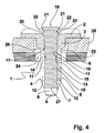
- Fig. 4 shows a relation to the sectional view according to Fig. 3 rotated by 90 degrees sectional view now again the embodiment of an inventive expansion rivet according Fig. 1 with the insertion pin 15 in the final assembly position according to Fig. 3 , Of the Representation according to Fig. 4 It can be seen that in the final assembly position formed on the head-side guide tongues 11 locking projections 13 engage in the formed on the pin shank 16 recesses 18 so that the insertion pin 15 is secured against unintentional slipping out of the insert body 1 against the insertion.
Landscapes
- Engineering & Computer Science (AREA)
- General Engineering & Computer Science (AREA)
- Mechanical Engineering (AREA)
- Insertion Pins And Rivets (AREA)
Description
- Die Erfindung betrifft einen Spreizniet gemäß dem Oberbegriff des Patentanspruches 1.
- Ein derartiger Spreizniet ist aus
GB 971,370 A - Aus
US 6,074,144 A ist ein Spreizniet bekannt, der zwei Klemmschenkel aufweist, von denen jeder über einen Kopfabschnitt verfügt, der sich von einem einem Kopfschaft benachbarten Anbindungsbereich radial nach außen über den Umfang des Kopfschaftes hinaus erstreckt. Weiterhin weist jeder Klemmschenkel an dem dem Kopfschaft abgewandten Ende des Kopfabschnittes einen Endabschnitt auf, der sich von dem Verbindungsbereich mit dem jeweiligen Kopfabschnitt radial nach innen erstreckt. Die Endabschnitte sind mit ihren den Kopfabschnitten abgewandten Enden miteinander verbunden, wobei der Verbindungsbereich durch eine Materialverdickung verstärkt ist. - Ein weiterer Spreizniet ist aus
DE 102 57 194 A1 bekannt. Dieser vorbekannte Spreizniet verfügt über einen länglichen Einsatzkörper, der einen Kopfteller und zwei an dem Kopfteller angesetzte Klemmschenkel aufweist. Weiterhin ist der vorbekannte Spreizniet mit einem Einschiebestift ausgebildet, der verschiebbar in dem Einsatzkörper gelagert ist. Der Einsatzkörper kommt bei Bewegen von einer Vormontagestellung in eine Endmontagestellung mit den Klemmschenkeln in Kontakt und übt auf die Klemmschenkel eine radial nach außen wirkende Kraft aus, so dass bei einer bestimmungsgemäßen Anordnung in beispielsweise einem Trägerteil sowie einem mit dem Spreizniet an dem Trägerteil zu verbindenden Anbauteil eingebrachten Ausnehmungen die Klemmschenkel radial nach außen getrieben werden und den Rand einer in dem Trägerteil eingebrachten Ausnehmung, in den der Spreizniet eingefügt ist, hintergreifen. - Der Erfindung liegt die Aufgabe zugrunde, einen Spreizniet der eingangs genannten Art anzugeben, der sich bei einer hohen Klemmwirkung durch eine verhältnismäßig geringe Einfügekraft des Einschiebestiftes auszeichnet, wobei der Spreizniet sehr zuverlässig bestimmungsgemäß in dem oder jedem Bauteil, mit dem er zu verbinden ist, einfügbar ist.
- Diese Aufgabe wird bei einem Spreizniet der eingangs genannten Art erfindungsgemäß mit den kennzeichnenden Merkmalen des Patentanspruches 1 gelöst.
- Dadurch, dass bei dem erfindungsgemäßen Spreizniet die Fußabschnitte der Klemmschenkel über einen in seiner Festigkeit gegenüber den Fußabschnitten geschwächten sowie bei Einfügen des Spreizniets der radial nach innen erfolgenden Verformung der Klemmschenkel als Scharnier wirkenden Sollbruchstellenabschnitt miteinander verbunden sind, lässt sich der Spreizniet sehr zuverlässig und einfach bestimmungsgemäß anordnen, da selbst bei einem verkanteten Einsetzen in einer Ausnehmung nicht die Gefahr besteht, dass ein Klemmschenkel abgespreizt und der Spreizniet somit gegebenenfalls unbrauchbar wird. Bei Überführen des Einsatzkörpers von der Vormontagestellung in die Endmontagestellung jedoch wird der Sollbruchstellenabschnitt mit einem verhältnismäßig geringen Kraftaufwand zerstört, so dass die Klemmschenkel für ein sehr weites, allein durch die Materialeigenschaften der Spreizschenkel kraftbestimmtes Aufspreizen freigegeben sind.
- Weitere zweckmäßige Ausgestaltungen von erfindungsgemäßen Spreiznieten sind Gegenstand der Unteransprüche.
- Zweckmäßige Ausgestaltungen und Vorteile von erfindungsgemässen Spreiznieten ergeben sich aus der nachfolgenden Beschreibung von Ausführungsbeispielen mit Bezug auf die Figuren der Zeichnung. Es zeigen:
- Fig. 1
- in einer perspektivischen Ansicht ein Ausführungsbeispiel eines erfindungsgemäßen Spreizniets mit einem Einsatzkörper und mit einem Einschiebestift, der im Bereich eines Stiftkopfes einen Anschlagvorsprung aufweist,
- Fig. 2
- in einer Schnittansicht das Ausführungsbeispiel gemäß
Fig. 1 in einer bestimmungsgemäßen Anordnung zum Verbinden eines Anbauteils an einem Trägerteil mit dem Einschiebestift in einer Vormontagestellung, - Fig. 3
- in einer Schnittansicht den Spreizniet gemäss
Fig. 1 undFig. 2 in der Anordnung gemässFig. 2 mit dem Einschiebestift in einer Endmontagestellung und - Fig. 4
- in einer weiteren Schnittansicht das Ausführungsbeispiel gemäss
Fig. 1 bis Fig. 3 mit dem Einschiebestift in der Endmontagestellung. -
Fig. 1 zeigt in einer perspektivischen Ansicht ein Ausführungsbeispiel eines erfindungsgemässen Spreizniets, der über einen länglichen Einsatzkörper 1 verfügt. Der Einsatzkörper 1 ist mit einem flachen Kopfteller 2 ausgebildet, an den an einer Flachseite ein Kopfschaft 3 angesetzt ist. Der Kopfschaft 3 ist radial innenseitig des Randes des Kopftellers 2 angeordnet. An den Kopfteller 2 sind bei diesem Ausführungsbeispiel zwei einander gegenüberliegende Klemmschenkel 4, 5 angeformt, die sich von dem Kopfteller 2 wegerstrecken. - Jeder Klemmschenkel 4, 5 verfügt über einen Kopfabschnitt 6, der sich von dem dem Kopfschaft 3 benachbarten Anbindungsbereich radial nach außen über den Umfang des Kopfschaftes 3 hinaus erstreckt. An dem dem Kopfschaft 3 abgewandten Ende des Kopfabschnittes 6 verfügt jeder Klemmschenkel 4, 5 über einen Endabschnitt 7, der sich von dem Verbindungsbereich mit dem jeweiligen Kopfabschnitt 6 radial nach innen erstreckt. An dem dem Kopfabschnitt 6 abgewandten Ende des Endabschnittes 7 ist jeder Klemmschenkel 4, 5 mit einem Fußabschnitt 8 ausgebildet. Die Fußabschnitte 8 der Klemmschenkel 4, 5 sind radial nach innen gebogen und nach Herstellung des Einsatzkörpers 1 über einen Sollbruchstellenabschnitt 9 miteinander verbunden.
- Bei dem dargestellten Ausführungsbeispiel weist der Sollbruchstellenabschnitt 9 eine Einkerbung 10 auf, die die Materialstärke des Sollbruchstellenabschnittes 9 im Bereich der Einkerbung 10 gegenüber der Materialstärke der Fußabschnitte 8 verringert.
- Bei einem nicht dargestellten, gegenüber dem Ausführungsbeispiel von
Fig. 1 abgewandelten Ausführungsbeispiel weist der Sollbruchstellenabschnitt 9 alternativ oder ergänzend zu der Einkerbung 10 wenigstens eine Schwächungsausnehmung auf, die sich in die Längsrichtung des Einsatzkörpers 1 durch den Sollbruchstellenabschnitt 9 erstreckt. - Weiterhin lässt sich
Fig. 1 entnehmen, dass an jedem Klemmschenkel 4, 5 eine kopfseitige Führungszunge 11, die an dem jeweiligen Kopfabschnitt 6 angeformt ist, und eine fußseitige Führungszunge 12 angeordnet ist, die an dem Endabschnitt 7 angeformt ist und sich von dem Verbindungsbereich des Kopfabschnittes 6 mit dem Endabschnitt 7 in Richtung des Fußabschnittes 8 erstreckt. Die Führungszungen 11, 12 sind außenseitig an den Klemmschenkeln 4, 5 an voneinander abgewandten Randseiten der Klemmschenkel 4, 5 angeordnet. Die kopfseitigen Führungszungen 11 sind mit jeweils einem Rastvorsprung 13 ausgebildet, der sich radial nach innen erstreckt. Im Bereich der fußseitigen Führungszungen 12 ist an dem Endabschnitt 7 jedes Klemmschenkels 4, 5 eine Spreizrampe 14 ausgebildet, die sich von dem Verbindungsbereich des Kopfabschnittes 6 mit dem Endabschnitt 7 radial nach innen ansteigend in Richtung des jeweiligen Fußabschnittes 8 erstreckt. - Der erfindungsgemässe Spreizniet gemäss dem Ausführungsbeispiel von
Fig. 1 ist weiterhin mit einem länglichen Einschiebestift 15 ausgestattet, der verschiebbar in dem Einsatzkörper 1 gelagert ist. Der Einschiebestift 15 verfügt über einen Stiftschaft 16 mit einem im Wesentlichen rechteckigen Querschnitt, der durch eine in dem Kopfteller 2 und dem Fußschaft 3 ausgebildete, entsprechend dimensionierte Einschiebeausnehmung 17 durchgreift. In etwa in der Mitte des Stiftschaftes 16 sind an einander gegenüberliegenden Außenseiten jeweils eine Rastausnehmung 18 ausgebildet, die sich in Querrichtung des Stiftschaftes 16 erstrecken. - Bei dem Ausführungsbeispiel gemäss
Fig. 1 verfügt der Einschiebestift 15 an einem Ende des Stiftschaftes 16 über einen Stiftkopf 19, der mit Anschlagvorsprüngen 20 ausgebildet ist, die sich radial nach außen über den Stiftschaft 16 erstrecken. Weiterhin weist der Stiftkopf 19 in einem axialen Abstand von den Anschlagvorsprüngen 20 auf der den Rastausnehmungen 18 gegenüberliegenden Seite angeordnete Griffränder 21 auf, die radial über zwischen den Anschlagvorsprüngen 20 und den Griffrändem 21 ausgebildeten Zwischennuten 22 überstehen. -
Fig. 2 zeigt in einer Schnittansicht eine Abwandlung des Ausführungsbeispiels gemäßFig. 1 , bei der der Stiftkopf 19 glattwandig abgerundet ausgebildet ist, in einer Einbausituation, in der der Einsatzkörper 1 des Spreizniets in eine in einem Trägerteil 23 als erstem Bauteil eingebrachte Trägerteilausnehmung 24, und in eine in einem Anbauteil 25 als zweitem Bauteil eingebrachte Anbauteilausnehmung 26 eingefügt ist. In der Darstellung gemässFig. 2 ist der Einschiebestift 15 in einer Vormontageanordnung, in der ein dem Klemmschenkel 4, 5 zugewandtes Fußende 27 des Stiftschaftes 16 des Einschiebestiftes 15 mit den Spreizrampen 14 bezüglich einer Spreizung der Klemmschenkel 4, 5 noch nicht wirksam in Kontakt ist. In dieser Vormontagestellung ist der Spreizniet gemäss dem erläuterten Ausführungsbeispiel in der Trägerteilausnehmung 24 aufgrund des schräggestellten Kopfabschnittes 6 mit einer gewissen Verspannung gehalten. Aufgrund der durch die Materialschwächung hervorgerufenen Scharnierfunktion des Sollbruchstellenabschnittes 9 ist der erfindungsgemäße Spreizniet unter Einfedern der Klemmschenkel 4, 5 radial nach innen mit einem verhältnismässig geringen Kraftaufwand durch die bei dieser Anordnung gegenüber der Anbauteilausnehmung 26 kleiner dimensionierten Trägerteilausnehmung 24 einfügbar. -
Fig. 3 zeigt in einer Schnittansicht die Abwandlung des Ausführungsbeispiels eines erfindungsgemässen Spreizniets gemässFig. 2 mit dem Einschiebestift 15 in einer Endmontagestellung, in der das den Klemmschenkeln 4, 5 zugewandte Fußende 27 des Stiftschaftes 16 über die dem jeweiligen Fußabschnitt 8 zugewandten Enden der Spreizrampen 14 hinaussteht. In dieser Endmontagestellung sind die Klemmschenkel 4, 5 aufgrund der Anlage der Spreizrampen 14 an dem Stiftschaft 15 mit einer damit verbundenen radial nach außen wirkenden Kraft radial nach außen bewegt, um die Sollauszugskraft des Spreizniets sicherzustellen. Aufgrund der bei Bewegen des Einschiebestiftes 15 von der Vormontagestellung gemässFig. 2 in die Endmontagestellung gemässFig. 3 auf die Klemmschenkel 4, 5 ausgeübten radial wirkenden Kraft wurde die Verbindung der Fußabschnitte 8 über den Sollbruchstellenabschnitt 9 zerstört, so dass die Fußabschnitte 8 nunmehr einen in etwa dem Durchmesser des Stiftschaftes 16 entsprechenden Abstand voneinander aufweisen. Dadurch ist auch der radiale Aufspreizweg der Klemmschenkel 4, 5 maximiert, da nunmehr keinerlei durch die Verbindung der Fußabschnitte 8 verursachten gegenwirkenden Kräfte vorhanden sind. - Weiterhin lässt sich der Darstellung gemäss
Fig. 3 entnehmen, dass bei dem Ausführungsbeispiel gemässFig. 2 undFig. 3 mit einem glattwandigen Stiftkopf 19 aufgrund der nunmehr voneinander beabstandeten Fußabschnitte 8 der Einschiebestift 15 durch den Einsatzkörper 1 hindurch verschiebbar ist. -
Fig. 4 zeigt eine gegenüber der Schnittansicht gemässFig. 3 um 90 Grad gedrehte Schnittansicht nunmehr wieder des Ausführungsbeispiels eines erfindungsgemässen Spreizniets gemässFig. 1 mit dem Einschiebestift 15 in der Endmontagestellung gemässFig. 3 . Der Darstellung gemässFig. 4 ist zu entnehmen, dass in der Endmontagestellung die an den kopfseitigen Führungszungen 11 ausgebildeten Rastvorsprünge 13 in die an dem Stiftschaft 16 ausgebildeten Rastausnehmungen 18 eingreifen, so dass der Einschiebestift 15 gegen unbeabsichtigtes Herausrutschen aus dem Einsatzkörper 1 entgegen der Einführrichtung gesichert ist. - Weiterhin lässt sich der Darstellung gemäss
Fig. 4 entnehmen, dass bei dem dargestellten Ausführungsbeispiel die Anschlagvorsprünge 20 in der Endmontagestellung an dem Kopfteller 2 anliegen, so dass sichergestellt ist, dass über Eingriff in die Zwischennut 22, beispielsweise mit einem Werkzeug, der Einschiebestift 15 nach Überwinden des durch die Verrastung der Rastersprünge 13 in die Rastausnehmungen 18 hervorgerufenen Widerstands wieder entgegen der Einführrichtung aus dem Eintrittskörper 1 entfernbar ist.
Claims (3)
- Spreizniet mit einem länglichen Einsatzkörper (1), der einen Kopfteller (2) und wenigstens zwei mit dem Kopfteller (2) in Verbindung stehende Klemmschenkel (4, 5) aufweist, und mit einem in dem Einsatzkörper (1) verschiebbaren länglichen Einschiebestift (15), der bei Bewegen von einer Vormontagestellung in eine Endmontagestellung mit den Klemmschenkeln (4, 5) in Kontakt kommt und auf die Klemmschenkel (4, 5) eine radial nach außen wirkende Kraft ausübt, wobei die Klemmschenkel (4, 5) dem Kopfteller (2) abgewandte Fußabschnitte (8) aufweisen, wobei jeder Klemmschenkel (4, 5) über einen Kopfabschnitt (6) verfügt, der sich von einem einem Kopfschaft (3) benachbarten Anbindungsbereich radial nach außen über den Umfang des Kopfschaftes (3) hinaus erstreckt, wobei an dem dem Kopfschaft (3) abgewandten Ende des Kopfabschnittes (6) jeder Klemmschenkel (4, 5) über einen Endabschnitt (7) verfügt, der sich von dem Verbindungsbereich mit dem jeweiligen Kopfabschnitt (6) radial nach innen erstreckt, und wobei die Fußabschnitte (8) radial nach innen gebogen sind, dadurch gekennzeichnet, dass die Fußabschnitte über einen Sollbruchstellenabschnitt (9) miteinander verbunden sind, wobei die Festigkeit des Sollbruchstellenabschnitts (9) so eingerichtet ist, dass die Verbindung der Fußabschnitte (8) über den Sollbruchstellenabschnitt (9) in der Endmontagestellung des Einschiebestiftes (15) zerstört ist und die Fußabschnitte (8) somit voneinander getrennt sind,
- Spreizniet nach Anspruch 1, dadurch gekennzeichnet, dass der Sollbruchstellenabschnitt (9) eine gegenüber den an den Sollbruchstellenabschnitt (9) benachbarten Bereichen der Fußabschnitte (8) geringere Materialstärke aufweist.
- Spreizniet nach Anspruch 2, dadurch gekennzeichnet, dass der Sollbruchstellenabschnitt (9) eine Einkerbung (10) aufweist.
Applications Claiming Priority (2)
| Application Number | Priority Date | Filing Date | Title |
|---|---|---|---|
| DE102008012767A DE102008012767A1 (de) | 2008-03-05 | 2008-03-05 | Spreizniet |
| PCT/EP2009/000810 WO2009109272A1 (de) | 2008-03-05 | 2009-02-06 | Spreizniet |
Publications (2)
| Publication Number | Publication Date |
|---|---|
| EP2252803A1 EP2252803A1 (de) | 2010-11-24 |
| EP2252803B1 true EP2252803B1 (de) | 2012-09-19 |
Family
ID=40599901
Family Applications (1)
| Application Number | Title | Priority Date | Filing Date |
|---|---|---|---|
| EP09717994A Active EP2252803B1 (de) | 2008-03-05 | 2009-02-06 | Spreizniet |
Country Status (3)
| Country | Link |
|---|---|
| EP (1) | EP2252803B1 (de) |
| DE (1) | DE102008012767A1 (de) |
| WO (1) | WO2009109272A1 (de) |
Families Citing this family (2)
| Publication number | Priority date | Publication date | Assignee | Title |
|---|---|---|---|---|
| DE102017128814A1 (de) * | 2017-12-05 | 2019-06-06 | Illinois Tool Works Inc. | Befestigungsvorrichtung |
| DE102017129954A1 (de) * | 2017-12-14 | 2019-06-19 | Illinois Tool Works Inc. | Befestigungssystem zur Befestigung eines Bauteils an einer Fahrzeugkarosserie |
Family Cites Families (6)
| Publication number | Priority date | Publication date | Assignee | Title |
|---|---|---|---|---|
| GB971370A (en) | 1962-07-10 | 1964-09-30 | Ft Products Ltd | Improvements in and relating to rivets |
| US3487745A (en) * | 1968-05-28 | 1970-01-06 | Olin Mathieson | Fastener |
| US3482482A (en) * | 1968-07-26 | 1969-12-09 | Usm Corp | Drive anchor fastening devices |
| US6074144A (en) | 1999-01-14 | 2000-06-13 | Illinois Tool Works Inc. | Fastener with retained movable pin |
| JP3772254B2 (ja) * | 2000-03-17 | 2006-05-10 | 株式会社パイオラックス | クリップ |
| JP4213381B2 (ja) | 2001-12-07 | 2009-01-21 | 株式会社パイオラックス | クリップ |
-
2008
- 2008-03-05 DE DE102008012767A patent/DE102008012767A1/de not_active Withdrawn
-
2009
- 2009-02-06 WO PCT/EP2009/000810 patent/WO2009109272A1/de not_active Ceased
- 2009-02-06 EP EP09717994A patent/EP2252803B1/de active Active
Also Published As
| Publication number | Publication date |
|---|---|
| EP2252803A1 (de) | 2010-11-24 |
| DE102008012767A1 (de) | 2009-09-24 |
| WO2009109272A1 (de) | 2009-09-11 |
Similar Documents
| Publication | Publication Date | Title |
|---|---|---|
| EP2049807B1 (de) | Vorrichtung zum befestigen eines anbauteiles und eines trägerteiles in einem abstand voneinander | |
| EP2395259B1 (de) | Spannvorrichtung mit Rastspange | |
| EP2601418B1 (de) | Spreizniet | |
| EP2193277B1 (de) | Vorrichtung zum befestigen eines anbauteiles an einem trägerteil | |
| EP2411684A1 (de) | Spreizniet | |
| DE102004036621B4 (de) | Spreizniet | |
| DE102009016633A1 (de) | Befestigungsmittel zur Vormontage eines stiftförmigen Verbindungsmittels in einer Durchgangsöffnung eines Bauteils | |
| EP2513391B1 (de) | Teleskopstütze für den baubereich | |
| WO2007124824A1 (de) | Befestigungsvorrichtung | |
| WO2009012947A1 (de) | Befestigungselement zum verbinden eines trägerteiles mit einem anbauteil | |
| EP2171302B1 (de) | Freilaufkupplung | |
| EP2198170B1 (de) | Vorrichtung zum befestigen eines anbauteiles an einem trägerteil | |
| EP3153721B1 (de) | Duebelanordnung fuer eine vorrichtung zum verbinden zweier moebelelemente | |
| EP2252803B1 (de) | Spreizniet | |
| EP2598761B1 (de) | Vorrichtung zum aufstecken auf einen gewindebolzen | |
| EP3052820A1 (de) | Verankerungsvorrichtung | |
| DE3302752C3 (de) | ||
| EP2281122B1 (de) | Befestigungsklammer sowie anordnung mit einer befestigungssklammer und mit einem anbauteil | |
| DE202008003162U1 (de) | Spreizniet | |
| DE102012107009A1 (de) | Dübel | |
| EP2628971B1 (de) | Scheibenbremse für ein Nutzfahrzeug | |
| DE102008039108B4 (de) | Vorrichtung zum Befestigen eines Anbauteiles an einem Trägerteil | |
| DE202012102428U1 (de) | Halteelement zur Befestigung in einer Trägeröffnung | |
| DE102018102261A1 (de) | Spreizdübel | |
| WO2017055559A1 (de) | Baustütze |
Legal Events
| Date | Code | Title | Description |
|---|---|---|---|
| PUAI | Public reference made under article 153(3) epc to a published international application that has entered the european phase |
Free format text: ORIGINAL CODE: 0009012 |
|
| 17P | Request for examination filed |
Effective date: 20101005 |
|
| AK | Designated contracting states |
Kind code of ref document: A1 Designated state(s): AT BE BG CH CY CZ DE DK EE ES FI FR GB GR HR HU IE IS IT LI LT LU LV MC MK MT NL NO PL PT RO SE SI SK TR |
|
| AX | Request for extension of the european patent |
Extension state: AL BA RS |
|
| DAX | Request for extension of the european patent (deleted) | ||
| 17Q | First examination report despatched |
Effective date: 20110713 |
|
| GRAP | Despatch of communication of intention to grant a patent |
Free format text: ORIGINAL CODE: EPIDOSNIGR1 |
|
| GRAS | Grant fee paid |
Free format text: ORIGINAL CODE: EPIDOSNIGR3 |
|
| GRAA | (expected) grant |
Free format text: ORIGINAL CODE: 0009210 |
|
| AK | Designated contracting states |
Kind code of ref document: B1 Designated state(s): AT BE BG CH CY CZ DE DK EE ES FI FR GB GR HR HU IE IS IT LI LT LU LV MC MK MT NL NO PL PT RO SE SI SK TR |
|
| REG | Reference to a national code |
Ref country code: GB Ref legal event code: FG4D Free format text: NOT ENGLISH |
|
| REG | Reference to a national code |
Ref country code: CH Ref legal event code: EP |
|
| REG | Reference to a national code |
Ref country code: IE Ref legal event code: FG4D Free format text: LANGUAGE OF EP DOCUMENT: GERMAN |
|
| REG | Reference to a national code |
Ref country code: AT Ref legal event code: REF Ref document number: 576183 Country of ref document: AT Kind code of ref document: T Effective date: 20121015 |
|
| REG | Reference to a national code |
Ref country code: DE Ref legal event code: R096 Ref document number: 502009004778 Country of ref document: DE Effective date: 20121115 |
|
| PG25 | Lapsed in a contracting state [announced via postgrant information from national office to epo] |
Ref country code: FI Free format text: LAPSE BECAUSE OF FAILURE TO SUBMIT A TRANSLATION OF THE DESCRIPTION OR TO PAY THE FEE WITHIN THE PRESCRIBED TIME-LIMIT Effective date: 20120919 Ref country code: LT Free format text: LAPSE BECAUSE OF FAILURE TO SUBMIT A TRANSLATION OF THE DESCRIPTION OR TO PAY THE FEE WITHIN THE PRESCRIBED TIME-LIMIT Effective date: 20120919 Ref country code: NO Free format text: LAPSE BECAUSE OF FAILURE TO SUBMIT A TRANSLATION OF THE DESCRIPTION OR TO PAY THE FEE WITHIN THE PRESCRIBED TIME-LIMIT Effective date: 20121219 Ref country code: HR Free format text: LAPSE BECAUSE OF FAILURE TO SUBMIT A TRANSLATION OF THE DESCRIPTION OR TO PAY THE FEE WITHIN THE PRESCRIBED TIME-LIMIT Effective date: 20120919 |
|
| REG | Reference to a national code |
Ref country code: NL Ref legal event code: VDEP Effective date: 20120919 |
|
| REG | Reference to a national code |
Ref country code: LT Ref legal event code: MG4D Effective date: 20120919 |
|
| PG25 | Lapsed in a contracting state [announced via postgrant information from national office to epo] |
Ref country code: SI Free format text: LAPSE BECAUSE OF FAILURE TO SUBMIT A TRANSLATION OF THE DESCRIPTION OR TO PAY THE FEE WITHIN THE PRESCRIBED TIME-LIMIT Effective date: 20120919 Ref country code: GR Free format text: LAPSE BECAUSE OF FAILURE TO SUBMIT A TRANSLATION OF THE DESCRIPTION OR TO PAY THE FEE WITHIN THE PRESCRIBED TIME-LIMIT Effective date: 20121220 Ref country code: LV Free format text: LAPSE BECAUSE OF FAILURE TO SUBMIT A TRANSLATION OF THE DESCRIPTION OR TO PAY THE FEE WITHIN THE PRESCRIBED TIME-LIMIT Effective date: 20120919 Ref country code: SE Free format text: LAPSE BECAUSE OF FAILURE TO SUBMIT A TRANSLATION OF THE DESCRIPTION OR TO PAY THE FEE WITHIN THE PRESCRIBED TIME-LIMIT Effective date: 20120919 |
|
| PG25 | Lapsed in a contracting state [announced via postgrant information from national office to epo] |
Ref country code: IS Free format text: LAPSE BECAUSE OF FAILURE TO SUBMIT A TRANSLATION OF THE DESCRIPTION OR TO PAY THE FEE WITHIN THE PRESCRIBED TIME-LIMIT Effective date: 20130119 Ref country code: ES Free format text: LAPSE BECAUSE OF FAILURE TO SUBMIT A TRANSLATION OF THE DESCRIPTION OR TO PAY THE FEE WITHIN THE PRESCRIBED TIME-LIMIT Effective date: 20121230 Ref country code: CZ Free format text: LAPSE BECAUSE OF FAILURE TO SUBMIT A TRANSLATION OF THE DESCRIPTION OR TO PAY THE FEE WITHIN THE PRESCRIBED TIME-LIMIT Effective date: 20120919 Ref country code: EE Free format text: LAPSE BECAUSE OF FAILURE TO SUBMIT A TRANSLATION OF THE DESCRIPTION OR TO PAY THE FEE WITHIN THE PRESCRIBED TIME-LIMIT Effective date: 20120919 Ref country code: NL Free format text: LAPSE BECAUSE OF FAILURE TO SUBMIT A TRANSLATION OF THE DESCRIPTION OR TO PAY THE FEE WITHIN THE PRESCRIBED TIME-LIMIT Effective date: 20120919 Ref country code: RO Free format text: LAPSE BECAUSE OF FAILURE TO SUBMIT A TRANSLATION OF THE DESCRIPTION OR TO PAY THE FEE WITHIN THE PRESCRIBED TIME-LIMIT Effective date: 20120919 |
|
| PG25 | Lapsed in a contracting state [announced via postgrant information from national office to epo] |
Ref country code: PT Free format text: LAPSE BECAUSE OF FAILURE TO SUBMIT A TRANSLATION OF THE DESCRIPTION OR TO PAY THE FEE WITHIN THE PRESCRIBED TIME-LIMIT Effective date: 20130121 Ref country code: PL Free format text: LAPSE BECAUSE OF FAILURE TO SUBMIT A TRANSLATION OF THE DESCRIPTION OR TO PAY THE FEE WITHIN THE PRESCRIBED TIME-LIMIT Effective date: 20120919 Ref country code: SK Free format text: LAPSE BECAUSE OF FAILURE TO SUBMIT A TRANSLATION OF THE DESCRIPTION OR TO PAY THE FEE WITHIN THE PRESCRIBED TIME-LIMIT Effective date: 20120919 |
|
| PLBE | No opposition filed within time limit |
Free format text: ORIGINAL CODE: 0009261 |
|
| STAA | Information on the status of an ep patent application or granted ep patent |
Free format text: STATUS: NO OPPOSITION FILED WITHIN TIME LIMIT |
|
| PG25 | Lapsed in a contracting state [announced via postgrant information from national office to epo] |
Ref country code: BG Free format text: LAPSE BECAUSE OF FAILURE TO SUBMIT A TRANSLATION OF THE DESCRIPTION OR TO PAY THE FEE WITHIN THE PRESCRIBED TIME-LIMIT Effective date: 20121219 Ref country code: DK Free format text: LAPSE BECAUSE OF FAILURE TO SUBMIT A TRANSLATION OF THE DESCRIPTION OR TO PAY THE FEE WITHIN THE PRESCRIBED TIME-LIMIT Effective date: 20120919 |
|
| 26N | No opposition filed |
Effective date: 20130620 |
|
| PG25 | Lapsed in a contracting state [announced via postgrant information from national office to epo] |
Ref country code: IT Free format text: LAPSE BECAUSE OF FAILURE TO SUBMIT A TRANSLATION OF THE DESCRIPTION OR TO PAY THE FEE WITHIN THE PRESCRIBED TIME-LIMIT Effective date: 20120919 |
|
| BERE | Be: lapsed |
Owner name: A. RAYMOND ET CIE Effective date: 20130228 |
|
| PG25 | Lapsed in a contracting state [announced via postgrant information from national office to epo] |
Ref country code: MC Free format text: LAPSE BECAUSE OF NON-PAYMENT OF DUE FEES Effective date: 20130228 |
|
| REG | Reference to a national code |
Ref country code: CH Ref legal event code: PL |
|
| REG | Reference to a national code |
Ref country code: DE Ref legal event code: R097 Ref document number: 502009004778 Country of ref document: DE Effective date: 20130620 |
|
| GBPC | Gb: european patent ceased through non-payment of renewal fee |
Effective date: 20130206 |
|
| PG25 | Lapsed in a contracting state [announced via postgrant information from national office to epo] |
Ref country code: LI Free format text: LAPSE BECAUSE OF NON-PAYMENT OF DUE FEES Effective date: 20130228 Ref country code: CH Free format text: LAPSE BECAUSE OF NON-PAYMENT OF DUE FEES Effective date: 20130228 |
|
| PG25 | Lapsed in a contracting state [announced via postgrant information from national office to epo] |
Ref country code: CY Free format text: LAPSE BECAUSE OF FAILURE TO SUBMIT A TRANSLATION OF THE DESCRIPTION OR TO PAY THE FEE WITHIN THE PRESCRIBED TIME-LIMIT Effective date: 20120919 |
|
| REG | Reference to a national code |
Ref country code: IE Ref legal event code: MM4A |
|
| PG25 | Lapsed in a contracting state [announced via postgrant information from national office to epo] |
Ref country code: IE Free format text: LAPSE BECAUSE OF NON-PAYMENT OF DUE FEES Effective date: 20130206 Ref country code: BE Free format text: LAPSE BECAUSE OF NON-PAYMENT OF DUE FEES Effective date: 20130228 Ref country code: GB Free format text: LAPSE BECAUSE OF NON-PAYMENT OF DUE FEES Effective date: 20130206 |
|
| REG | Reference to a national code |
Ref country code: DE Ref legal event code: R082 Ref document number: 502009004778 Country of ref document: DE |
|
| PG25 | Lapsed in a contracting state [announced via postgrant information from national office to epo] |
Ref country code: MT Free format text: LAPSE BECAUSE OF FAILURE TO SUBMIT A TRANSLATION OF THE DESCRIPTION OR TO PAY THE FEE WITHIN THE PRESCRIBED TIME-LIMIT Effective date: 20120919 |
|
| REG | Reference to a national code |
Ref country code: AT Ref legal event code: MM01 Ref document number: 576183 Country of ref document: AT Kind code of ref document: T Effective date: 20140206 |
|
| PG25 | Lapsed in a contracting state [announced via postgrant information from national office to epo] |
Ref country code: AT Free format text: LAPSE BECAUSE OF NON-PAYMENT OF DUE FEES Effective date: 20140206 |
|
| PG25 | Lapsed in a contracting state [announced via postgrant information from national office to epo] |
Ref country code: TR Free format text: LAPSE BECAUSE OF FAILURE TO SUBMIT A TRANSLATION OF THE DESCRIPTION OR TO PAY THE FEE WITHIN THE PRESCRIBED TIME-LIMIT Effective date: 20120919 |
|
| PG25 | Lapsed in a contracting state [announced via postgrant information from national office to epo] |
Ref country code: HU Free format text: LAPSE BECAUSE OF FAILURE TO SUBMIT A TRANSLATION OF THE DESCRIPTION OR TO PAY THE FEE WITHIN THE PRESCRIBED TIME-LIMIT; INVALID AB INITIO Effective date: 20090206 Ref country code: LU Free format text: LAPSE BECAUSE OF NON-PAYMENT OF DUE FEES Effective date: 20130206 Ref country code: MK Free format text: LAPSE BECAUSE OF FAILURE TO SUBMIT A TRANSLATION OF THE DESCRIPTION OR TO PAY THE FEE WITHIN THE PRESCRIBED TIME-LIMIT Effective date: 20120919 |
|
| REG | Reference to a national code |
Ref country code: FR Ref legal event code: PLFP Year of fee payment: 8 |
|
| REG | Reference to a national code |
Ref country code: FR Ref legal event code: PLFP Year of fee payment: 9 |
|
| REG | Reference to a national code |
Ref country code: FR Ref legal event code: PLFP Year of fee payment: 10 |
|
| P01 | Opt-out of the competence of the unified patent court (upc) registered |
Effective date: 20230524 |
|
| PGFP | Annual fee paid to national office [announced via postgrant information from national office to epo] |
Ref country code: DE Payment date: 20260218 Year of fee payment: 18 |
|
| PGFP | Annual fee paid to national office [announced via postgrant information from national office to epo] |
Ref country code: FR Payment date: 20260218 Year of fee payment: 18 |