EP2253246B1 - Charnière à réglage d'angle - Google Patents
Charnière à réglage d'angle Download PDFInfo
- Publication number
- EP2253246B1 EP2253246B1 EP09170810A EP09170810A EP2253246B1 EP 2253246 B1 EP2253246 B1 EP 2253246B1 EP 09170810 A EP09170810 A EP 09170810A EP 09170810 A EP09170810 A EP 09170810A EP 2253246 B1 EP2253246 B1 EP 2253246B1
- Authority
- EP
- European Patent Office
- Prior art keywords
- face
- wedge
- angle
- gear
- hole
- Prior art date
- Legal status (The legal status is an assumption and is not a legal conclusion. Google has not performed a legal analysis and makes no representation as to the accuracy of the status listed.)
- Active
Links
Images







Classifications
-
- A—HUMAN NECESSITIES
- A47—FURNITURE; DOMESTIC ARTICLES OR APPLIANCES; COFFEE MILLS; SPICE MILLS; SUCTION CLEANERS IN GENERAL
- A47C—CHAIRS; SOFAS; BEDS
- A47C1/00—Chairs adapted for special purposes
- A47C1/02—Reclining or easy chairs
- A47C1/022—Reclining or easy chairs having independently-adjustable supporting parts
- A47C1/024—Reclining or easy chairs having independently-adjustable supporting parts the parts, being the back-rest, or the back-rest and seat unit, having adjustable inclination
- A47C1/026—Reclining or easy chairs having independently-adjustable supporting parts the parts, being the back-rest, or the back-rest and seat unit, having adjustable inclination by means of a peg-and-notch or pawl-and-ratchet mechanism
-
- A—HUMAN NECESSITIES
- A47—FURNITURE; DOMESTIC ARTICLES OR APPLIANCES; COFFEE MILLS; SPICE MILLS; SUCTION CLEANERS IN GENERAL
- A47C—CHAIRS; SOFAS; BEDS
- A47C7/00—Parts, details, or accessories of chairs or stools
- A47C7/36—Supports for the head or the back
- A47C7/38—Supports for the head or the back for the head, e.g. detachable
-
- A—HUMAN NECESSITIES
- A47—FURNITURE; DOMESTIC ARTICLES OR APPLIANCES; COFFEE MILLS; SPICE MILLS; SUCTION CLEANERS IN GENERAL
- A47C—CHAIRS; SOFAS; BEDS
- A47C7/00—Parts, details, or accessories of chairs or stools
- A47C7/50—Supports for the feet or the legs
- A47C7/506—Supports for the feet or the legs of adjustable type
- A47C7/5066—Supports for the feet or the legs of adjustable type by rotation
-
- Y—GENERAL TAGGING OF NEW TECHNOLOGICAL DEVELOPMENTS; GENERAL TAGGING OF CROSS-SECTIONAL TECHNOLOGIES SPANNING OVER SEVERAL SECTIONS OF THE IPC; TECHNICAL SUBJECTS COVERED BY FORMER USPC CROSS-REFERENCE ART COLLECTIONS [XRACs] AND DIGESTS
- Y10—TECHNICAL SUBJECTS COVERED BY FORMER USPC
- Y10T—TECHNICAL SUBJECTS COVERED BY FORMER US CLASSIFICATION
- Y10T403/00—Joints and connections
- Y10T403/32—Articulated members
- Y10T403/32254—Lockable at fixed position
- Y10T403/32262—At selected angle
- Y10T403/32319—At selected angle including pivot stud
- Y10T403/32327—At selected angle including pivot stud including radially spaced detent or latch component
- Y10T403/32336—Engaging notch or recess in outer periphery of component
Definitions
- This invention relates to an angle-adjustable hinge used for furniture with which a back is pivoted as to adjust an inclination angle of the back.
- DE 20 2008 004 242 U1 discloses an angle-adjustable hinge.
- an angle-adjustable hinge 43 is constructed that a second arm 32 having an arc-shaped gear portion 34 of a first arm 31 forming a case portion 33 is provided, wedge-shaped window portions 35 are formed on plate piece portions 37, a floating wedge member 36 is inserted to the wedge-shaped window portions 35, the gear portion 34 of the second arm 32 and two parallel plate piece portions 38 are inserted between the two parallel plate piece portions 37 of the case portion 33, and a small pin 39 is inserted to small holes 40 and 41 to connect the first arm 31 and the second arm 32 as to oscillate around an axis 42.
- the gear portion 34 has many fine gear teeth 48, the floating wedge member 36 also has fine gear teeth 49. If these gears are not certainly engaged with high dimensional accuracy, contact pressure on the gear teeth 48 and 49 becomes excessive, and cutting and rapid abrasion may be generated.
- angle-adjustable hinge including features of claim 1. Furthermore detailed embodiments are described in the dependent claim 2.
- An angle-adjustable hinge relating to the present invention is used for sofas, chairs, beds, headrests, footrests, oscillating doors, etc. to hold a member which oscillates (inclines) up and down with a predetermined angle range as to adjust the inclination angle.
- the angle-adjustable hinge is applied to a sofa S as shown in Figures 6A and 6B to pivot a backrest S 1 to a seat S 0 as to freely incline backward.
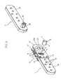
- FIG. 1 through 4 An embodiment shown in Figures 1 through 4 is provided with a first member 1 having a first attachment portion 18 of plate shape and a second member 2 having a second attachment portion 19 of plate shape.
- Plural attachment small holes 15 are disposed on the first attachment portion 18 and the second attachment portion 19, fixation members such as screws and rivets are inserted to the attachment small holes 15 to fix each of frames of the backrest S 1 to the seat S 0 as shown with broken lines in Figure 6B .
- the first member 1 has a case portion 3 having a pair of facing plate portions 17, and an approximately disc-shaped gear member 4 is held within the case portion 3 as to freely rotate.
- the facing plate portion 17 is approximately rectangular, two fixation holes 16 are formed through the facing plate portion 17, two fixation holes 16a are formed through the first attachment portion 18, a caulking member 14 is inserted to the fixation holes 16 and 16a to firmly fix the first attachment portion 18 between the parallel two facing plate portions 17, and the case portion 3 is unitedly composed of a part of the first attachment portion 18 and the facing plate portions 17.
- the middle ones are for a mutual connecting rod of later-described cover K.
- a mark 6 represents a floating wedge member having a lateral dimension equal to or slightly larger than a dimension between outer faces of the facing plate portions 17. The floating wedge member 6 is inserted as to bridge the left and right wedge-shaped window portions 5, and assembled as to move within the wedge-shaped window portions 5.
- a circular low protrusion 24 having a sliding peripheral face 22 is formed unitedly with (continuing from) each of side faces 4a and 4b as to protrude.
- the circular low protrusion 24 is fit to the circular holding hole 21 by the above-mentioned screwing (caulking) of the caulking members 14. That is to say, the sliding peripheral face 22 of the circular low protrusion 24 is fit to (held by) the circular holding hole 21 of each of the facing plate portions 17 as to be slidable with extremely low contact pressure. Therefore, the gear member 4 is held within the case portion 3 as to rotate around a first axis C 1 .
- a female screw hole 29 is formed along an axis of the fitting shaft portion 20.
- gear teeth 25 are disposed on an arc-shaped range having a central angle of the peripheral face less than 180° on the gear member 4. That is to say, the gear member 4 has an arc-shaped outer toothed face Y. And, the gear member 4 is provided with a through hole 23 having a non-circular configuration such as regular hexagonal, polygonal, asterisk, etc., corresponding to the fitting shaft portion 20. And, the fitting shaft portion 20 of the second member 2 can be inserted to the through hole 23 from both sides in the direction of the axis C 1 .
- the second member 2 is formed as to be symmetric when inverted for 180° around a central axis in longitudinal direction, a member having this configuration can serve as both of the second member 2 and the first member 1.
- the circular low protrusion 24 of the gear member 4 fit to the case portion 3 and the outer face of the facing plate portion 17 approximately form the same plane. That is to say, height dimension of the circular low protrusion 24 is set to be approximately same as thickness dimension of the facing plate portion 17.
- a cover K made of plastic or thin metal plate is attached, and the fitting shaft portion 20 is inserted to the through hole 23 with stopping by a stopping member B.
- the gear member 4 has the concavo-convex gear teeth 25 from a push-back protrusion 10 protruding from the arc of which center is a center of axis P 1 of the through hole 23 along a range (of 100° to 120°) slightly (for 10° to 30°) over a quarter of circle (90° ) on the same arc in the direction of an arrow N.
- a push-out protrusion 12, protruding from the arc of which center is the center of axis P 1 is provided on the end portion of the range on which the concavo-convex gear teeth 25 are formed.
- a radius R 0 of the sliding peripheral face 22 of which center is the center of axis P 1 is set to be 60 to 80% to a gear radius Rg of the concavo-convex gear teeth 25 (the outer toothed face Y) of which center is the center of axis P 1 .
- the radius R 0 is set to be smaller than 60% to the gear radius Rg, the circular low protrusion 24 as an axis to the concavo-convex gear teeth 25 becomes small, contact pressure becomes excessive, and cutting and abnormal abrasion may be generated for defects of engagement of the concavo-convex gear teeth 25.
- the wedge-shaped window portion 5 formed to be concave to the center when the first axis C 1 is on the center side, is a wedge-shaped hole expanding in the arrow N direction.
- the wedge-shaped window portion 5 is formed on each of the facing plate portions 17 as to have the same configuration and penetrating the case portion 3.
- a wedge sliding face 8 is formed on an outer side of the wedge-shaped window portion 5.
- the wedge sliding face 8 is formed arc-shaped of which center is a second axis C 2 eccentric to the first axis C 1 ,
- the second axis C 2 may be an infinitely distant point and the whole or a part of the wedge sliding face 8 may be straight (not shown in Figures).
- the configuration of the wedge sliding face 8 may be (i) arc-shaped, (ii)straight, (iii)combination of an arc and a straight line, (iv)a polygonal line in which plural straight short lines are serially connected, etc.
- the wedge-shaped window portion 5 has a retreat space 11 to store the floating wedge member 6 as to release the engagement of the inner toothed face 7 and the gear member 4 on an end portion on the side of the arrow N direction.
- the wedge-shaped window portion 5 has a contact staged portion 28 on an arc face 26 on the inner side.
- 0ne face side of the floating wedge member 6 is an inner toothed face 7 having concavo-convex gear to engage with the gear member 4, and another face side of the floating wedge member 6 is a contact face 9 to contact the wedge sliding face 8 of the wedge-shaped window portion 5.
- a guiding slope 27 which can contact the contact staged portion 28, is formed.
- the contact face 9 of the floating wedge member 6 is formed as an arc having approximately same configuration as the wedge sliding face 8.
- the configuration of the contact face 9 may be (i) a polygonal line in which plural straight short lines are serially connected, (ii)a configuration in which straight short lines and arc-shaped short lines are serially connected.
- the case portion 3 is provided with an elastic member 13 to elastically push the floating wedge member 6 toward the gear member 4.
- the elastic member 13 is a plate spring composed of a strip of steel plate, of which both ends are attached to the first attachment portion 18, contacts a middle portion of the contact face 9 of the floating wedge member 6.
- the floating wedge member 6 is disposed in a space Z formed between the gear member 4 and the wedge sliding face 8, and elastically pushed toward the gear member 4.
- one wedge-shaped window portion 5 is formed with one plate portion 17 in the construction described above, it is also possible to compose the wedge-shaped window portion 5 with two or more members (not shown in Figures). Further, it is sufficient that the wedge sliding face 8 is composed as to form the wedge-shaped space Z between the wedge sliding face 8 and the arc-shaped outer toothed face Y of the gear member 4 when observed in the axis C 1 direction. The space Z does not need to be closed like a window (not shown in Figures).
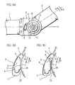
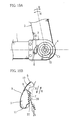
- Figures 7A through 12 are explanatory views of function of the angle-adjustable hinge A.
- the second member 2 oscillates against the first member 1 gradually in the arrow N direction ( Figures 8A through 9B ).
- the second member 2 oscillates in an arrow R direction to recover the straight state.
- the movement of the angle-adjustable hinge A is described below with this cycle.
- the fitting shaft portion 20 is fit to the through hole 23 of the first member 1 to attach the second member 2 to the first member 1 as the first member 1 and the second member 2 are in a straight line (refer to Figure 7A ).
- the floating wedge member 6 engages with the concavo-convex gear teeth 25 on the push-out protrusion 12 side by the inner toothed face 7 and contacts the wedge sliding face 8 by the contact face 9 to restrict the rotation of the gear member 4 in the arrow R direction (refer to Figure 7B ).
- This state is an oscillation starting state in which the angle formed by the first member 1 and the second member 2 is the oscillation start angle ⁇ 0 . In the oscillation starting state, the second member 2 oscillates against the first member 1 in the arrow N direction.
- the floating wedge member 6 engages with the concavo-convex gear teeth 25 by the inner toothed face 7 and contacts the wedge sliding face 8 by the contact face 9 to restrict the rotation of the second member 2 in the arrow R direction. Therefore, the second member 2 is kept with a desired inclination angle.
- the sliding peripheral face 22 broadly slides on the circular holding hole 21 to firmly keep the posture of the second member 2 because the gear member 4 is held by the circular low protrusion 24 fit to the circular holding hole 21.
- This state is an oscillation ending state in which the angle formed by the first member 1 and the second member 2 is the oscillation end angle ⁇ 1 .
- the second member 2 does not oscillate against the first member 1 in the arrow N direction beyond the oscillation end angle ⁇ 1.
- the second member 2 in the oscillation starting state, stopping the oscillation in the arrow R direction, is oscillated by an oscillation unit angle ⁇ in the arrow N direction, and kept with a desired inclination angle.
- the second member 2 becomes free oscillation state within the range from the oscillation start angle ⁇ 0 to the oscillation end angle ⁇ 1 .
- the engagement of the floating wedge member 6 and the gear member 4 is recovered to return to the oscillation starting state by making the first member 1 and the second member 2 in straight state (with the oscillation start angle ⁇ 0 ).
- the oscillation start angle ⁇ 0 0°
- the oscillation end angle ⁇ 1 95°
- the oscillation unit angle ⁇ as the oscillation angle when the inner toothed face 7 goes over one of the concavo-convex gear teeth 25 is set to be 5°
- these values are examples and may be changed.
- first attachment portion 18 and the second attachment portion 19 may be formed into desired configurations.
- first member 1, provided with the case portion 3 to which the covers K are attached may have configurations of the first attachment portion 18 different from the configuration used in the above-described embodiment.
- second member 2 may similarly have configurations of the second attachment portion 19 different from the configuration used in the above-described embodiment.
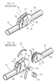
- the configurations of the first member 1 shown in Figures 13A through 13D and the configurations of the second member 2 shown in Figures 14A through 14D may be freely selected and combined, and various forms can be elected corresponding to uses of the angle-adjustable hinge A and fixation method of the first attachment portion 18 and the second attachment portion 19 to sofas, etc.
- the fitting shaft portion 20 of the second member 2 is inserted from the left side to the through hole 23 on the first member 1 of the angle-adjustable hinge A on the left side, and the fitting shaft portion 20 of the second member 2 is inserted from the right side to the through hole 23 on the first member 1 of the angle-adjustable hinge A on the right side. That is to say, the fitting shaft portion 20 of the second member 2 can be inserted to the through hole 23 on the first member 1 from both of the left and right sides.
- the angle-adjustable hinges A can be composed of entirely common parts. And, also in combinations of Figure 13A or 13B and Figure 14A, 14B, or 14C , although it is necessary to make the first attachment portion 18 and the second attachment portion 19 symmetric corresponding to each other, functional parts assembled within the case portion 3 of the first member 1, especially difficult to make and expensive for the required working accuracy, material, and heat treatment, can be commonly used as they are.
- the oscillation start angle ⁇ 0 is changed as the second member 2 with inclination of the predetermined angle ⁇ starts the oscillation against the first member 1 in the arrow N direction.
- the movable area from the oscillation start angle ⁇ 0 to the oscillation end angle ⁇ 1 is same as in the above-described embodiment. Therefore, the oscillation end angle ⁇ 1 is inclined in the arrow N direction for the predetermined angle ⁇ .
- the oscillation start angle ⁇ 0 and the oscillation end angle ⁇ 1 of the second member 2 against the first member 1 are changed for the predetermined angle ⁇ .
- the oscillation end angle ⁇ 1 is further inclined for the predetermined angle ⁇ in the arrow N direction. That is to say, the oscillation start angle ⁇ 0 and the oscillation end angle ⁇ 1 can be changed for every predetermined angle ⁇ , and the oscillation start angle ⁇ 0 and the oscillation end angle ⁇ 1 of the second member 2 against the first member 1 can be changed corresponding to uses.
- the configurations of the through hole 23 and the fitting shaft portion 20, not restricted to regular hexagon may be preferably regular triangle, square, regular polygonal such as regular octagonal, other non-circular configurations such as cross, asterisk, etc.
- the first member 1 and the second member 2 can be easily connected because the first member 1 holding the approximately disc-shaped gear member 4 having the non-circular through hole 23 as to freely rotate around an axis C 1 of the through hole 23, and the second member 2 on which the fitting shaft portion 20 detachably inserted to the through hole 23 of the gear member 4 is protruding, are provided, the wedge sliding face 8 is disposed on the first member 1 side to form the wedge-shaped space Z between the wedge sliding face 8 and the arc-shaped outer toothed face Y of the gear member 4 when observed in the direction of the axis C 1 , the floating wedge member 6, of which one face side is an arc-shaped inner toothed face 7 engaged with the outer toothed face Y of the gear member 4 and the outer face side is the contact face 9 to contact the wedge sliding face 8, and movable within the wedge-shaped space Z, is provided, the contact face 9 of the floating wedge member 6 contacts the wedge sliding face 8, the inner toothed face 7 engages with the outer toothed face
- the hinge can easily correspond to the design change with common use of the case portion 3, the production is made easy, and the quality is kept high because expensive functional parts which require the most high standards of working accuracy, material, heat treatment, etc. can be assembled within the case portion 3 of the first member 1. And, adjustment of the oscillation start angle ⁇ 0 and the oscillation end angle ⁇ 1 of the second member 2 against the first member 1 can be easily conducted to enlarge the uses.
- the construction and configurations of the wedge sliding face 8 and members near the wedge sliding face 8 can be simplified to make the product light weight and compact because the first member 1 has the case portion 3, the wedge-shaped window portion 5 is formed on the case portion 3, and the wedge sliding face 8 is composed of a part of the wedge-shaped window portion 5.
- the first member 1 and the second member 2 can be easily connected only by the insertion of the fitting shaft portion 20 of the second member 2 to the through hole 23 of the first member 1 because the present invention is provided with the first member 1 provided with the case portion 3 holding the approximately disc-shaped gear member 4 having the non-circular through hole 23 as to freely rotate, the second member 2 on which the fitting shaft portion 20, detachably inserted to the through hole 23 of the gear member 4, is protruding, the wedge-shaped window portion 5 formed on the case portion 3, and the floating wedge member 6, movably disposed within the wedge-shaped window portion 5, in which one side face is an inner toothed face 7 to engage with the gear member 4 and another side is the contact face 9 to contact the wedge sliding face 8 of the wedge-shaped window portion 5, to restrict the gear member 4 from oscillation in one direction against the case portion 3 by the engagement of the inner toothed face 7 with the gear member 4 and the contact of the contact face 9 and the wedge sliding face 8.
- the hinge can easily correspond to the design change with common use of the case portion 3, the production is made easy, and the quality is kept high because expensive functional parts which require the most high standards of working accuracy, material, heat treatment, etc. can be assembled within the case portion 3 of the first member 1. And, adjustment of the oscillation start angle ⁇ 0 and the oscillation end angle ⁇ 1 of the second member 2 against the first member 1 can be easily conducted to enlarge the uses.
- the hinge is excellent in durability because the circular low protrusion 24 having the sliding peripheral face 22 is protruding from the side face 4a and the side face 4b on the gear member 4, and the case portion 3 is provided with the pair of facing plate portions 17 each of which has the circular holding hole 21 to which the sliding peripheral face 22 of the circular low protrusion 24 is slidably fit.
Landscapes
- Health & Medical Sciences (AREA)
- Dentistry (AREA)
- General Health & Medical Sciences (AREA)
- Chairs For Special Purposes, Such As Reclining Chairs (AREA)
- Pivots And Pivotal Connections (AREA)
Claims (2)
- Charnière à angle réglable ayant une structure dans laquelle :un premier élément (1) maintenant un élément d'engrenage approximativement en forme de disque (4) ayant un trou traversant (23) de façon à tourner librement autour d'un axe (C1) du trou traversant (23), et un second élément (2) sur lequel une partie formant arbre de raccord (20) inséré de façon amovible dans le trou traversant (23) de l'élément d'engrenage (4) est saillante, sont prévus ;une face coulissante en coin (8) est disposée sur le côté premier élément (1) pour former un espace en forme de coin (Z) entre la face coulissante en coin (8) et une face dentée extérieure en forme d'arc (Y) de l'élément d'engrenage (4) quand on regarde dans la direction de l'axe (C1) ;un élément formant coin flottant (6) dont un côté face est une face dentée intérieure en forme d'arc (7) en prise avec la face dentée extérieure (Y) de l'élément d'engrenage (4) et un côté face extérieure est une face de contact (9) pour entrer en contact avec la face coulissante en coin (8), et mobile à l'intérieur de l'espace en forme de coin (Z), est prévu ; etla face de contact (9) de l'élément formant coin flottant (6) entre en contact avec la face coulissante en coin (8), la face dentée intérieure (7) met en prise la face dentée extérieure (Y), et l'oscillation de l'élément d'engrenage (4) dans une direction vers le premier élément (1) est limitée par le travail de coin de l'élément formant coin flottant (6) entre la face dentée extérieure (Y) et la face coulissante en coin (8) ;caractérisée en ce que :le trou traversant (23) est formé de manière non circulaire ;la partie formant arbre de raccord (20) est unie au second élément (2)une partie formant enveloppe (3) du premier élément (1) est munie d'un couple de parties plates se faisant face (17), chacune d'elles ayant une partie formant fenêtre en forme de coin (5), dont une partie forme la face coulissante en coin (8), et un trou de maintien circulaire (21) auquel une face périphérique coulissante (22) d'une protubérance basse circulaire (24) de l'élément d'engrenage (4) est ajustée de manière coulissante ;la partie formant arbre de raccord (20) du second élément (2) est composée de façon à être insérée dans les deux côtés du trou traversant (23) du premier élément (1) comme la charnière à angle réglable peut être appliquée à différentes sortes de meublesle trou traversant non circulaire (23) est un polygone régulier, et chacun d'un angle de début d'oscillation (Ø0) et d'un angle de fin d'oscillation (Ø1) du second élément (2) contre le premier élément (1) peut être changé pour un angle prédéterminé (θ) ; etune première partie de fixation en forme de plaque (18) et l'élément d'engrenage (4) sont maintenus entre le couple de parties plates se faisant face (17),et le couple de parties plates se faisant face (17) maintient la première partie de fixation (18) pour former la partie formant enveloppe (3), dans laquelle l'élément d'engrenage (4) est maintenu à l'intérieur de la partie formant enveloppe (3) de façon à tourner librement quand il n'est pas en prise avec la face dentée intérieure (7) de l'élément formant coin flottant (6).
- Charnière à angle réglable selon la revendication 1, dans laquelle un rayon (Ro) dont le centre est un centre d'axe (P1) de la face périphérique coulissante (22) est fixé pour faire 60 à 80 % d'un rayon d'engrenage (Rg) de dents d'engrenage concavo-convexes (25) dont le centre est le centre d'axe (P1) du trou traversant (23) dans l'élément d'engrenage (4).
Priority Applications (1)
| Application Number | Priority Date | Filing Date | Title |
|---|---|---|---|
| PL09170810T PL2253246T3 (pl) | 2009-05-22 | 2009-09-21 | Zawiasa z regulowanym kątem otwarcia |
Applications Claiming Priority (1)
| Application Number | Priority Date | Filing Date | Title |
|---|---|---|---|
| JP2009124333A JP4418519B1 (ja) | 2009-05-22 | 2009-05-22 | 角度調整金具 |
Publications (2)
| Publication Number | Publication Date |
|---|---|
| EP2253246A1 EP2253246A1 (fr) | 2010-11-24 |
| EP2253246B1 true EP2253246B1 (fr) | 2013-01-16 |
Family
ID=42016891
Family Applications (1)
| Application Number | Title | Priority Date | Filing Date |
|---|---|---|---|
| EP09170810A Active EP2253246B1 (fr) | 2009-05-22 | 2009-09-21 | Charnière à réglage d'angle |
Country Status (6)
| Country | Link |
|---|---|
| US (1) | US8156612B2 (fr) |
| EP (1) | EP2253246B1 (fr) |
| JP (1) | JP4418519B1 (fr) |
| CN (1) | CN101892781B (fr) |
| ES (1) | ES2399490T3 (fr) |
| PL (1) | PL2253246T3 (fr) |
Cited By (2)
| Publication number | Priority date | Publication date | Assignee | Title |
|---|---|---|---|---|
| DE202017107438U1 (de) | 2017-12-06 | 2017-12-21 | Malu GmbH & Co. KG | Winkelverstellbares Scharnier |
| DE102017129057A1 (de) | 2017-12-06 | 2019-06-06 | Malu GmbH & Co. KG | Winkelverstellbares Scharnier |
Families Citing this family (34)
| Publication number | Priority date | Publication date | Assignee | Title |
|---|---|---|---|---|
| DE102006058948A1 (de) * | 2006-11-30 | 2008-06-12 | Kintec-Solution Gmbh | Gliederkette |
| CN201814188U (zh) * | 2010-06-30 | 2011-05-04 | 梁华春 | 三挡焊接合页 |
| JP5514753B2 (ja) * | 2011-02-16 | 2014-06-04 | 直伸 山下 | 角度調整金具 |
| JP5177719B1 (ja) * | 2011-10-05 | 2013-04-10 | 直伸 山下 | 角度調整具 |
| US20130149023A1 (en) * | 2011-12-09 | 2013-06-13 | United Technologies Corporation | Adjustable clevis assembly |
| WO2013104115A1 (fr) * | 2012-01-11 | 2013-07-18 | Lu Wei | Régulateur de charnière |
| DE102012100443B3 (de) * | 2012-01-19 | 2013-05-23 | Hettich Franke Gmbh & Co. Kg | Schwenkbeschlag für ein Möbel, insbesondere ein Polstermöbel |
| JP5091362B1 (ja) * | 2012-03-21 | 2012-12-05 | 直伸 山下 | 角度調整金具 |
| ITMI20120390U1 (it) * | 2012-10-31 | 2014-05-01 | Motion S R L | Dispositivo di movimentazione a cricchetto |
| TWI492028B (zh) * | 2012-12-18 | 2015-07-11 | Hon Hai Prec Ind Co Ltd | 旋轉機構及具有該旋轉機構的電子裝置 |
| TWI533103B (zh) * | 2013-01-31 | 2016-05-11 | 緯創資通股份有限公司 | 電子裝置及其樞紐模組 |
| JP5555341B1 (ja) * | 2013-02-15 | 2014-07-23 | 直伸 山下 | 角度調整金具及び座椅子 |
| DE102013104692B4 (de) * | 2013-05-07 | 2014-12-31 | Ferdinand Lusch Gmbh & Co. Kg | Schwenkbeschlag für Sitz- und/oder Liegemöbel |
| JP5611416B1 (ja) | 2013-05-20 | 2014-10-22 | 山下 直伸 | 角度調整金具 |
| CN104433402B (zh) * | 2014-11-28 | 2017-08-15 | 叶佳 | 一种折叠坐具 |
| CN105902029B (zh) * | 2015-02-23 | 2018-11-02 | 东莞向阳金属制品有限公司 | 角度调整配件以及沙发 |
| US9399421B2 (en) * | 2015-10-19 | 2016-07-26 | Dongguan Weihong Hardware And Plastic Products Co., Ltd. | Hinge |
| CN105293409A (zh) * | 2015-10-23 | 2016-02-03 | 安徽徽王食品有限公司 | 一种用于蓝莓灌装机的灌装头固定装置 |
| US10138664B2 (en) | 2016-03-21 | 2018-11-27 | Taylor Made Group, Llc | Hinge with adjustable axis location and locking mechanism |
| US10900274B2 (en) | 2016-09-02 | 2021-01-26 | Pella Corporation | Anti-rattle elements for internal divider of glass assembly |
| US10876343B2 (en) | 2016-12-08 | 2020-12-29 | Pella Corporation | Casement sliding operator |
| US11454055B2 (en) | 2017-01-20 | 2022-09-27 | Pella Corporation | Window opening control systems and methods |
| JP2018179289A (ja) * | 2017-04-20 | 2018-11-15 | 山下 直伸 | 角度調整具 |
| DE102017110249A1 (de) * | 2017-05-11 | 2018-11-15 | Hettich Franke Gmbh & Co. Kg | Schwenkbeschlag und Möbel |
| DE102017110246A1 (de) * | 2017-05-11 | 2018-11-15 | Hettich Franke Gmbh & Co. Kg | Schwenkbeschlag und Möbel |
| JP6404400B1 (ja) * | 2017-05-11 | 2018-10-10 | 向陽技研株式会社 | 角度調整金具およびこれを用いた家具 |
| JP2019184012A (ja) * | 2018-04-14 | 2019-10-24 | 山下 直伸 | 角度調整具及び角度調整組立体 |
| CA3060764C (fr) | 2018-10-31 | 2022-08-23 | Pella Corporation | Actionneur coulissant pour module de fenetrage |
| CN111219114A (zh) * | 2018-11-27 | 2020-06-02 | 向阳技研株式会社 | 角度可调铰链 |
| CN210118467U (zh) * | 2019-03-29 | 2020-02-28 | 福迈克斯有限公司 | 阻尼器调节布置 |
| CA3081316C (fr) | 2019-05-24 | 2022-09-06 | Pella Corporation | Ensemble et composantes d`actionneur coulissant pour modules de fenetrage |
| DE102019119307A1 (de) * | 2019-07-16 | 2021-01-21 | Hettich Franke Gmbh & Co. Kg | Möbel und Verfahren zur Montage eines Möbels |
| CN115126769A (zh) * | 2022-07-25 | 2022-09-30 | 厦门海菱科技股份有限公司 | 一种铰链结构及车载显示器 |
| WO2025094658A1 (fr) * | 2023-10-30 | 2025-05-08 | 向陽エンジニアリング株式会社 | Dispositif de réglage d'angle |
Family Cites Families (13)
| Publication number | Priority date | Publication date | Assignee | Title |
|---|---|---|---|---|
| US3848923A (en) * | 1972-08-07 | 1974-11-19 | Brose & Co Metallwerk Max | Safety locking device for automobile reclining seats |
| DE2328908C3 (de) * | 1973-06-06 | 1980-05-14 | Metallwerk Max Brose Gmbh & Co, 8630 Coburg | Gelenkbeschlag für Sitze, insbesondere Kraftfahrzeugsitze |
| US4082352A (en) * | 1977-01-13 | 1978-04-04 | Lear Siegler, Inc. | Seat back recliner |
| US4133578A (en) * | 1977-11-21 | 1979-01-09 | General Motors Corporation | Seat back adjusting mechanism |
| JP2631760B2 (ja) * | 1990-06-28 | 1997-07-16 | 星野楽器株式会社 | 角度調節機構 |
| JP3436501B2 (ja) * | 1999-02-03 | 2003-08-11 | 向陽技研株式会社 | 角度調整具 |
| US6993808B1 (en) * | 2000-09-18 | 2006-02-07 | Lenjoy Medical Engineering, Inc. | Adjustable hinges for orthopedic splints |
| DE20112976U1 (de) * | 2001-08-13 | 2001-10-18 | Franke Gmbh & Co Kg | Schwenkbeschlag |
| JP3766669B2 (ja) | 2003-08-29 | 2006-04-12 | 直伸 山下 | 角度調整金具 |
| US7150073B2 (en) * | 2004-04-27 | 2006-12-19 | Delaware Capital Formation, Inc. | Hinge pin |
| US7984531B2 (en) * | 2005-09-23 | 2011-07-26 | Restorative Care Of America Incorporated | Rachet hinge for a knee or elbow orthosis |
| DE202008004242U1 (de) | 2008-03-25 | 2008-05-21 | Hsu, Teng Chuan, Shulin City | Winkelverstellbares Gelenk |
| JP4296223B1 (ja) * | 2008-05-23 | 2009-07-15 | 直伸 山下 | 角度調整金具 |
-
2009
- 2009-05-22 JP JP2009124333A patent/JP4418519B1/ja not_active Expired - Fee Related
- 2009-09-21 PL PL09170810T patent/PL2253246T3/pl unknown
- 2009-09-21 ES ES09170810T patent/ES2399490T3/es active Active
- 2009-09-21 EP EP09170810A patent/EP2253246B1/fr active Active
- 2009-10-22 CN CN200910207708.3A patent/CN101892781B/zh active Active
-
2010
- 2010-02-17 US US12/707,186 patent/US8156612B2/en not_active Expired - Fee Related
Cited By (2)
| Publication number | Priority date | Publication date | Assignee | Title |
|---|---|---|---|---|
| DE202017107438U1 (de) | 2017-12-06 | 2017-12-21 | Malu GmbH & Co. KG | Winkelverstellbares Scharnier |
| DE102017129057A1 (de) | 2017-12-06 | 2019-06-06 | Malu GmbH & Co. KG | Winkelverstellbares Scharnier |
Also Published As
| Publication number | Publication date |
|---|---|
| ES2399490T3 (es) | 2013-04-01 |
| JP4418519B1 (ja) | 2010-02-17 |
| PL2253246T3 (pl) | 2013-06-28 |
| EP2253246A1 (fr) | 2010-11-24 |
| CN101892781B (zh) | 2014-11-12 |
| CN101892781A (zh) | 2010-11-24 |
| US8156612B2 (en) | 2012-04-17 |
| US20100293748A1 (en) | 2010-11-25 |
| JP2010270858A (ja) | 2010-12-02 |
Similar Documents
| Publication | Publication Date | Title |
|---|---|---|
| EP2253246B1 (fr) | Charnière à réglage d'angle | |
| EP1510150B1 (fr) | Charnière à angle réglable | |
| CN110612047B (zh) | 枢转配件和家具 | |
| EP2767188B1 (fr) | Charnière réglable et canapé | |
| EP2805642B1 (fr) | Charnière à réglage d'angle | |
| EP2123194B1 (fr) | Charnière à angle ajustable | |
| EP2805645A1 (fr) | Canapé | |
| JP2013231487A (ja) | 角度調節器 | |
| JP6148683B2 (ja) | 時計ムーブメント用ばね | |
| JP5177719B1 (ja) | 角度調整具 | |
| JP2011167354A (ja) | 角度調節金具 | |
| EP3400836B1 (fr) | Outil de réglage d'angle et mobilier l'employant | |
| EP3058850B1 (fr) | Outil de réglage angulaire et canapé | |
| CN101321605A (zh) | 稳固的滑动结构可调整式扳手 | |
| JP5410573B2 (ja) | 角度調整方法 | |
| JP6872213B2 (ja) | 装身具の挟着構造 | |
| CN111219114A (zh) | 角度可调铰链 | |
| JP6012521B2 (ja) | 角度調節器 | |
| JP5509005B2 (ja) | レンチ | |
| JP5687781B2 (ja) | 角度調節金具 | |
| JP2008531391A (ja) | 車両シートおよびその他用途のための連続リクライナ機構 | |
| KR101722316B1 (ko) | 등받이 이동 의자 | |
| JP5390643B2 (ja) | 角度調整金具及び座いす | |
| WO2025094658A1 (fr) | Dispositif de réglage d'angle | |
| JP2012066147A5 (fr) |
Legal Events
| Date | Code | Title | Description |
|---|---|---|---|
| PUAI | Public reference made under article 153(3) epc to a published international application that has entered the european phase |
Free format text: ORIGINAL CODE: 0009012 |
|
| AK | Designated contracting states |
Kind code of ref document: A1 Designated state(s): AT BE BG CH CY CZ DE DK EE ES FI FR GB GR HR HU IE IS IT LI LT LU LV MC MK MT NL NO PL PT RO SE SI SK SM TR |
|
| AX | Request for extension of the european patent |
Extension state: AL BA RS |
|
| 17P | Request for examination filed |
Effective date: 20110112 |
|
| 17Q | First examination report despatched |
Effective date: 20110823 |
|
| GRAP | Despatch of communication of intention to grant a patent |
Free format text: ORIGINAL CODE: EPIDOSNIGR1 |
|
| GRAS | Grant fee paid |
Free format text: ORIGINAL CODE: EPIDOSNIGR3 |
|
| GRAA | (expected) grant |
Free format text: ORIGINAL CODE: 0009210 |
|
| AK | Designated contracting states |
Kind code of ref document: B1 Designated state(s): AT BE BG CH CY CZ DE DK EE ES FI FR GB GR HR HU IE IS IT LI LT LU LV MC MK MT NL NO PL PT RO SE SI SK SM TR |
|
| REG | Reference to a national code |
Ref country code: GB Ref legal event code: FG4D |
|
| REG | Reference to a national code |
Ref country code: CH Ref legal event code: EP |
|
| REG | Reference to a national code |
Ref country code: IE Ref legal event code: FG4D |
|
| REG | Reference to a national code |
Ref country code: AT Ref legal event code: REF Ref document number: 593394 Country of ref document: AT Kind code of ref document: T Effective date: 20130215 Ref country code: CH Ref legal event code: EP |
|
| REG | Reference to a national code |
Ref country code: DE Ref legal event code: R096 Ref document number: 602009012779 Country of ref document: DE Effective date: 20130314 |
|
| REG | Reference to a national code |
Ref country code: ES Ref legal event code: FG2A Ref document number: 2399490 Country of ref document: ES Kind code of ref document: T3 Effective date: 20130401 |
|
| REG | Reference to a national code |
Ref country code: AT Ref legal event code: MK05 Ref document number: 593394 Country of ref document: AT Kind code of ref document: T Effective date: 20130116 |
|
| REG | Reference to a national code |
Ref country code: NL Ref legal event code: VDEP Effective date: 20130116 |
|
| REG | Reference to a national code |
Ref country code: LT Ref legal event code: MG4D |
|
| REG | Reference to a national code |
Ref country code: PL Ref legal event code: T3 |
|
| PG25 | Lapsed in a contracting state [announced via postgrant information from national office to epo] |
Ref country code: AT Free format text: LAPSE BECAUSE OF FAILURE TO SUBMIT A TRANSLATION OF THE DESCRIPTION OR TO PAY THE FEE WITHIN THE PRESCRIBED TIME-LIMIT Effective date: 20130116 Ref country code: NO Free format text: LAPSE BECAUSE OF FAILURE TO SUBMIT A TRANSLATION OF THE DESCRIPTION OR TO PAY THE FEE WITHIN THE PRESCRIBED TIME-LIMIT Effective date: 20130416 Ref country code: LT Free format text: LAPSE BECAUSE OF FAILURE TO SUBMIT A TRANSLATION OF THE DESCRIPTION OR TO PAY THE FEE WITHIN THE PRESCRIBED TIME-LIMIT Effective date: 20130116 Ref country code: IS Free format text: LAPSE BECAUSE OF FAILURE TO SUBMIT A TRANSLATION OF THE DESCRIPTION OR TO PAY THE FEE WITHIN THE PRESCRIBED TIME-LIMIT Effective date: 20130516 Ref country code: BG Free format text: LAPSE BECAUSE OF FAILURE TO SUBMIT A TRANSLATION OF THE DESCRIPTION OR TO PAY THE FEE WITHIN THE PRESCRIBED TIME-LIMIT Effective date: 20130416 Ref country code: BE Free format text: LAPSE BECAUSE OF FAILURE TO SUBMIT A TRANSLATION OF THE DESCRIPTION OR TO PAY THE FEE WITHIN THE PRESCRIBED TIME-LIMIT Effective date: 20130116 Ref country code: SE Free format text: LAPSE BECAUSE OF FAILURE TO SUBMIT A TRANSLATION OF THE DESCRIPTION OR TO PAY THE FEE WITHIN THE PRESCRIBED TIME-LIMIT Effective date: 20130116 |
|
| PG25 | Lapsed in a contracting state [announced via postgrant information from national office to epo] |
Ref country code: GR Free format text: LAPSE BECAUSE OF FAILURE TO SUBMIT A TRANSLATION OF THE DESCRIPTION OR TO PAY THE FEE WITHIN THE PRESCRIBED TIME-LIMIT Effective date: 20130417 Ref country code: FI Free format text: LAPSE BECAUSE OF FAILURE TO SUBMIT A TRANSLATION OF THE DESCRIPTION OR TO PAY THE FEE WITHIN THE PRESCRIBED TIME-LIMIT Effective date: 20130116 Ref country code: LV Free format text: LAPSE BECAUSE OF FAILURE TO SUBMIT A TRANSLATION OF THE DESCRIPTION OR TO PAY THE FEE WITHIN THE PRESCRIBED TIME-LIMIT Effective date: 20130116 Ref country code: NL Free format text: LAPSE BECAUSE OF FAILURE TO SUBMIT A TRANSLATION OF THE DESCRIPTION OR TO PAY THE FEE WITHIN THE PRESCRIBED TIME-LIMIT Effective date: 20130116 Ref country code: PT Free format text: LAPSE BECAUSE OF FAILURE TO SUBMIT A TRANSLATION OF THE DESCRIPTION OR TO PAY THE FEE WITHIN THE PRESCRIBED TIME-LIMIT Effective date: 20130516 Ref country code: SI Free format text: LAPSE BECAUSE OF FAILURE TO SUBMIT A TRANSLATION OF THE DESCRIPTION OR TO PAY THE FEE WITHIN THE PRESCRIBED TIME-LIMIT Effective date: 20130116 |
|
| PG25 | Lapsed in a contracting state [announced via postgrant information from national office to epo] |
Ref country code: HR Free format text: LAPSE BECAUSE OF FAILURE TO SUBMIT A TRANSLATION OF THE DESCRIPTION OR TO PAY THE FEE WITHIN THE PRESCRIBED TIME-LIMIT Effective date: 20130116 |
|
| PG25 | Lapsed in a contracting state [announced via postgrant information from national office to epo] |
Ref country code: CZ Free format text: LAPSE BECAUSE OF FAILURE TO SUBMIT A TRANSLATION OF THE DESCRIPTION OR TO PAY THE FEE WITHIN THE PRESCRIBED TIME-LIMIT Effective date: 20130116 Ref country code: SK Free format text: LAPSE BECAUSE OF FAILURE TO SUBMIT A TRANSLATION OF THE DESCRIPTION OR TO PAY THE FEE WITHIN THE PRESCRIBED TIME-LIMIT Effective date: 20130116 Ref country code: RO Free format text: LAPSE BECAUSE OF FAILURE TO SUBMIT A TRANSLATION OF THE DESCRIPTION OR TO PAY THE FEE WITHIN THE PRESCRIBED TIME-LIMIT Effective date: 20130116 Ref country code: EE Free format text: LAPSE BECAUSE OF FAILURE TO SUBMIT A TRANSLATION OF THE DESCRIPTION OR TO PAY THE FEE WITHIN THE PRESCRIBED TIME-LIMIT Effective date: 20130116 Ref country code: DK Free format text: LAPSE BECAUSE OF FAILURE TO SUBMIT A TRANSLATION OF THE DESCRIPTION OR TO PAY THE FEE WITHIN THE PRESCRIBED TIME-LIMIT Effective date: 20130116 |
|
| PLBE | No opposition filed within time limit |
Free format text: ORIGINAL CODE: 0009261 |
|
| STAA | Information on the status of an ep patent application or granted ep patent |
Free format text: STATUS: NO OPPOSITION FILED WITHIN TIME LIMIT |
|
| PG25 | Lapsed in a contracting state [announced via postgrant information from national office to epo] |
Ref country code: CY Free format text: LAPSE BECAUSE OF FAILURE TO SUBMIT A TRANSLATION OF THE DESCRIPTION OR TO PAY THE FEE WITHIN THE PRESCRIBED TIME-LIMIT Effective date: 20130116 |
|
| 26N | No opposition filed |
Effective date: 20131017 |
|
| REG | Reference to a national code |
Ref country code: DE Ref legal event code: R097 Ref document number: 602009012779 Country of ref document: DE Effective date: 20131017 |
|
| PG25 | Lapsed in a contracting state [announced via postgrant information from national office to epo] |
Ref country code: MC Free format text: LAPSE BECAUSE OF FAILURE TO SUBMIT A TRANSLATION OF THE DESCRIPTION OR TO PAY THE FEE WITHIN THE PRESCRIBED TIME-LIMIT Effective date: 20130116 |
|
| REG | Reference to a national code |
Ref country code: CH Ref legal event code: PL |
|
| GBPC | Gb: european patent ceased through non-payment of renewal fee |
Effective date: 20130921 |
|
| REG | Reference to a national code |
Ref country code: FR Ref legal event code: ST Effective date: 20140530 |
|
| REG | Reference to a national code |
Ref country code: IE Ref legal event code: MM4A |
|
| PG25 | Lapsed in a contracting state [announced via postgrant information from national office to epo] |
Ref country code: IE Free format text: LAPSE BECAUSE OF NON-PAYMENT OF DUE FEES Effective date: 20130921 Ref country code: CH Free format text: LAPSE BECAUSE OF NON-PAYMENT OF DUE FEES Effective date: 20130930 Ref country code: GB Free format text: LAPSE BECAUSE OF NON-PAYMENT OF DUE FEES Effective date: 20130921 Ref country code: LI Free format text: LAPSE BECAUSE OF NON-PAYMENT OF DUE FEES Effective date: 20130930 |
|
| PG25 | Lapsed in a contracting state [announced via postgrant information from national office to epo] |
Ref country code: FR Free format text: LAPSE BECAUSE OF NON-PAYMENT OF DUE FEES Effective date: 20130930 |
|
| PG25 | Lapsed in a contracting state [announced via postgrant information from national office to epo] |
Ref country code: SM Free format text: LAPSE BECAUSE OF FAILURE TO SUBMIT A TRANSLATION OF THE DESCRIPTION OR TO PAY THE FEE WITHIN THE PRESCRIBED TIME-LIMIT Effective date: 20130116 |
|
| PG25 | Lapsed in a contracting state [announced via postgrant information from national office to epo] |
Ref country code: MT Free format text: LAPSE BECAUSE OF FAILURE TO SUBMIT A TRANSLATION OF THE DESCRIPTION OR TO PAY THE FEE WITHIN THE PRESCRIBED TIME-LIMIT Effective date: 20130116 |
|
| PG25 | Lapsed in a contracting state [announced via postgrant information from national office to epo] |
Ref country code: HU Free format text: LAPSE BECAUSE OF FAILURE TO SUBMIT A TRANSLATION OF THE DESCRIPTION OR TO PAY THE FEE WITHIN THE PRESCRIBED TIME-LIMIT; INVALID AB INITIO Effective date: 20090921 Ref country code: LU Free format text: LAPSE BECAUSE OF NON-PAYMENT OF DUE FEES Effective date: 20130921 Ref country code: MK Free format text: LAPSE BECAUSE OF FAILURE TO SUBMIT A TRANSLATION OF THE DESCRIPTION OR TO PAY THE FEE WITHIN THE PRESCRIBED TIME-LIMIT Effective date: 20130116 |
|
| PGFP | Annual fee paid to national office [announced via postgrant information from national office to epo] |
Ref country code: DE Payment date: 20250925 Year of fee payment: 17 |
|
| PGFP | Annual fee paid to national office [announced via postgrant information from national office to epo] |
Ref country code: PL Payment date: 20250808 Year of fee payment: 17 Ref country code: TR Payment date: 20250808 Year of fee payment: 17 Ref country code: IT Payment date: 20250926 Year of fee payment: 17 |
|
| PGFP | Annual fee paid to national office [announced via postgrant information from national office to epo] |
Ref country code: ES Payment date: 20251001 Year of fee payment: 17 |