EP2253247A1 - Élément pliant de mobilier - Google Patents
Élément pliant de mobilier Download PDFInfo
- Publication number
- EP2253247A1 EP2253247A1 EP09425192A EP09425192A EP2253247A1 EP 2253247 A1 EP2253247 A1 EP 2253247A1 EP 09425192 A EP09425192 A EP 09425192A EP 09425192 A EP09425192 A EP 09425192A EP 2253247 A1 EP2253247 A1 EP 2253247A1
- Authority
- EP
- European Patent Office
- Prior art keywords
- piece
- plane cam
- hub
- cam surface
- rotary joint
- Prior art date
- Legal status (The legal status is an assumption and is not a legal conclusion. Google has not performed a legal analysis and makes no representation as to the accuracy of the status listed.)
- Granted
Links
Images












Classifications
-
- A—HUMAN NECESSITIES
- A47—FURNITURE; DOMESTIC ARTICLES OR APPLIANCES; COFFEE MILLS; SPICE MILLS; SUCTION CLEANERS IN GENERAL
- A47B—TABLES; DESKS; OFFICE FURNITURE; CABINETS; DRAWERS; GENERAL DETAILS OF FURNITURE
- A47B3/00—Folding or stowable tables
- A47B3/08—Folding or stowable tables with legs pivoted to top or underframe
- A47B3/0803—Folding or stowable tables with legs pivoted to top or underframe the legs rotating around a vertical axis
-
- A—HUMAN NECESSITIES
- A47—FURNITURE; DOMESTIC ARTICLES OR APPLIANCES; COFFEE MILLS; SPICE MILLS; SUCTION CLEANERS IN GENERAL
- A47C—CHAIRS; SOFAS; BEDS
- A47C4/00—Foldable, collapsible or dismountable chairs
- A47C4/04—Folding chairs with inflexible seats
- A47C4/18—Folding chairs with inflexible seats having a frame made of metal
- A47C4/20—Folding chairs with inflexible seats having a frame made of metal with legs pivotably connected to seat or underframe
-
- A—HUMAN NECESSITIES
- A47—FURNITURE; DOMESTIC ARTICLES OR APPLIANCES; COFFEE MILLS; SPICE MILLS; SUCTION CLEANERS IN GENERAL
- A47C—CHAIRS; SOFAS; BEDS
- A47C7/00—Parts, details, or accessories of chairs or stools
- A47C7/36—Supports for the head or the back
- A47C7/40—Supports for the head or the back for the back
- A47C7/407—Supports for the head or the back for the back of collapsible type
Definitions
- the present invention relates to a folding piece of furniture, such as, for example, a stool, a table, a chair or the like.
- the object of the present invention is to provide a folding piece of furniture with a simple and versatile mechanism of opening and closing that will enable pieces of furniture of various types to be made.
- the above object is achieved by a piece of furniture having the characteristics forming the subject of Claim 1.
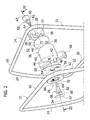
- FIG. 10 designated by 10 is a first embodiment of a piece of furniture according to the present invention.
- the piece of furniture 10 is in the form of a stool or of a table.
- the piece of furniture 10 comprises a first leg 12 and a second leg 14 and a resting element 16 that constitutes a seat in the case of a stool or else a resting surface in the case of a table.
- the legs 12, 14 are identical to one another and each of them has substantially the form of a quadrangular frame formed by a bent metal element and comprising a top branch 18, a bottom branch 20, a first upright, 22 and a second upright 24.
- the top branch 18 and the bottom branch 20 are parallel to one another, the first upright 22 extends in a vertical direction and the second upright 24 is inclined.
- Each leg 12, 14 in a side view has substantially the form of a right trapezium.
- the piece of furniture 10 comprises a first hub 26 and a second hub 28, fixed, respectively, to the first leg 12 and to the second leg 14.
- the hubs 26, 28 are fixed, for example by means of welding, in the corner formed between the top branch 18 and the first upright 22 of each leg 12, 14.
- Each hub 26, 28 has a respective plane cam surface 30, 31 and a through hole 32.
- the axes of the holes 32, designated, respectively, by 34 and 35, are orthogonal to the respective cam surfaces 30, 31.
- Each hub 26, 28 moreover has an open arched groove 36 on the respective cam surface 30, 31 extending according to an arc of circumference with centre on the respective axis 34, 35.
- the arched groove 36 extends according to an arc with an amplitude of approximately 180°.
- the piece of furniture 10 comprises a rotary joint 38 including a body 40 having two plane cam surfaces 42, 44 contained in respective non-parallel planes.
- the body 40 has two open holes 46 on the respective cam surfaces 42, 44 and with respective axes inclined with respect to one another.
- the axis of each hole 46 coincides with the respective axis 34, 35 of the respective hub 26, 28.
- the body 40 has two pins 48 projecting from the cam surfaces 42, 44 and eccentric with respect to the axis 34, 35 of the hole 46.
- the cam surface 42 is set facing and parallel to the cam surface 30 of the first hub 26.
- the cam surface 44 is set facing and parallel to the cam surface 31 of the second hub 28.
- a disk 50 made of a material with a low coefficient of friction is set between the cam surfaces 30, 42 and 31, 44 set facing one another.
- the disk 50 has a central hole 52 surrounded by a collar 54 that fits into the hole 32 of the respective hub 26, 28.
- the disk 50 moreover has an eccentric hole 56, within which the respective eccentric pin 48 of the rotary joint 38 extends.
- each hub 26, 28 is connected to the rotary joint 38 by means of a respective pin 58.
- Each pin 58 has a head 60, a first cylindrical portion 62, and a second cylindrical portion 64 with diameter smaller than the diameter of the first cylindrical portion 62.
- the head 60 of each pin 58 is preferably housed in a lowered seat 66 of the respective hub 26, 28, closed by a respective plug 67.
- Each pin 58 extends coaxially with respect to the respective axis 34, 35.
- the first cylindrical portion 62 of each pin 58 engages in a rotatable way the hole 32 of the respective hub 26, 28.
- the collar 54 surrounds the first cylindrical portion 62 and is set like a bushing between the outer surface of the first cylindrical portion 62 and the inner surface of the hole 32.
- the second cylindrical portion 64 of each pin 58 is fixed in the respective hole 46 of the rotary joint 38. Said fixing can be obtained by means of interference drive fit, welding, gluing or threaded coupling.
- connection between each hub 26, 28 and the rotary joint 38 obtained by means of the pins 58 keeps the cam surfaces 30, 31 of each hub 26, 28, constantly parallel with respect to, and set facing, the cam surfaces 42, 44 of the rotary joint 38, and enables rotation of the rotary joint 38 with respect to the hubs 26, 28.
- the pins 58 could be replaced by connection elements of a different type, designed to make a rotary connection between the rotary joint 38 and the respective hubs 26, 28, keeping the cam surfaces 30, 42 and 31, 44 constantly parallel to one another in pairs.
- the engagement between the pins 48 of the rotary joint 38 and the respective arched grooves 36 limits the movement of rotation of the rotary joint 38 with respect to the hubs 26, 28. In particular, the movement of rotation of the rotary joint 38 about the axes 34, 35 has an amplitude of approximately 180°.
- the rotary joint 38 comprises a flange 68, which is connected in a rotatable way to the body 40 about an axis 70 contained in a median plane with respect to the planes containing the cam surfaces 42, 44.
- the rotary connection between the flange 68 and the body 40 is obtained by means of a pin 72 that engages in a rotatable way a hole 74 of the flange 68 with interposition of a bushing 76.
- the pin 72 has an end 78 fixed in a hole 80 of the body 40, for example by means of threaded coupling.
- the flange 68 carries an articulation pin 82 with a axis 84 transverse with respect to the axis 70.
- the resting element 16 of the piece of furniture 10 is articulated to the flange 68 about the axis 84.
- the resting element 16 can oscillate about the axis 84 of the flange 68, and the flange 68 can in turn oscillate about the axis 70 with respect to the body 40 of the rotary joint 38. Consequently, the resting element 16 can perform movements of oscillation about two mutually orthogonal axes (the axes 70 and 84) with respect to the body 40 of the rotary joint 38.
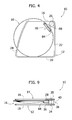
- Figures 4 and 9 illustrate the piece of furniture 10 in a closed configuration.
- the legs 12, 14 are substantially contained in respective planes parallel to one another, and the resting element 16 extends between the two legs 12, 14, substantially according to a plane parallel to the planes of the two legs 12, 14.
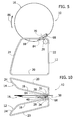
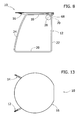
- Figures 5 to 8 and 10 to 13 illustrate, in side view and in plan view respectively, the sequence of operations for bringing the piece of furniture 10 into its open configuration.
- a first step illustrated in Figures 5 and 10
- the resting element 16 is turned upwards in the direction indicated by the arrow 86.
- This movement causes the rotation of the body 40 of the rotary joint 38 in a vertical plane.
- the rotation of the body 40 controls a movement of divarication of the legs 12, 14 as a result of the contact between the cam surfaces 42, 44 of the body 40 with the respective cam surfaces 30, 31 of the hubs 26, 28.
- FIG. 6 and 11 illustrate the piece of furniture at the end of the movement of raising of the resting element 16.
- the two legs 12, 14 are set substantially to form a V and are contained in respective convergent vertical planes.
- FIG. 7 and 12 show the piece of furniture 10 at the end of said rotation of the resting element 16.
- the legs 12, 14 remain immobile since the body 40 of the rotary joint 38 remains stationary with respect to the hubs 26, 28.
- the resting element 16 is made to oscillate about the axis 84 until it comes into contact with the top branches 18 of the legs 12, 14. In this condition, the piece of furniture 10 is in its open configuration, illustrated in Figures 1 , 8, and 13 .
- FIG. 14 to 29 A second embodiment of a piece of furniture according to the present invention is illustrated in Figures 14 to 29 .
- the elements corresponding to the ones described previously are designated by the same reference numbers.
- Figure 14 illustrates the piece of furniture 10 of this second embodiment in the open condition.
- the piece of furniture 10 is in the form of a stool or of a table.
- the main difference with respect to the embodiment described previously is that, in the open configuration, the legs 12, 14 of the piece of furniture 10 are substantially contained in respective planes inclined with respect to a vertical plane. This disposition enables a greater stability of the piece of furniture to be obtained.
- the piece of furniture 10 comprises, in a way identical to what has been described previously, a first hub 26 and a second hub 28 having respective cam surfaces 30, 31. Also in this case, each hub 26, 28 has a central through hole 32 and an arched groove 36.
- the arched groove 36 has an angular amplitude smaller than what is envisaged in the preceding embodiment.
- the rotary joint 38 comprises an external body 90 and an internal body 92, which can turn with respect to the external body 90 between two end-of-travel positions.
- the external body 90 of the rotary joint 38 has substantially the form of a ring with a cylindrical hole 94.
- the internal body 92 has a cylindrical portion that mates in rotation with the cylindrical hole 94 of the external body 90 with interposition of a bushing 96.
- the internal body 92 can rotate with respect to the external body 90 about an axis 97 orthogonal to the plane of representation of Figure 17 and coinciding with the axis of the cylindrical hole 94.
- the internal body 92 has two portions that project from opposite sides of the external body 90.
- the internal body 92 has two cam surfaces 42, 44 contained in non-parallel planes, similar to what is envisaged in the preceding embodiment.
- the internal body 92 has holes 46 engaged by the respective pins 58, as described previously.
- the internal body 92 moreover has pins 48 that engage the arched grooves 36 of the hubs 26, 28 in a way similar to what was described previously.
- the internal body 92 has an angular groove 98 that is engaged by an end 100 of the pin 72, which defines the axis of oscillation 70 of the flange 68.
- the engagement between the groove 98 and the end 100 of the pin 72 defines two end-of-travel positions of the internal body 92 with respect to the external body 90, which are angularly staggered with respect to one another by approximately 90°.
- the first uprights 22 of the legs 12, 14 are provided with respective connection elements 102 fixed to the ends of a flexible bar 104, for example made of elastomeric material, which connects the two legs 12, 14 to one another.
- the bar 104 could also be provided in the embodiment illustrated in Figures 1 to 13 . The bar 104 prevents the legs 12, 14 from rotating separately when the piece of furniture 10 is lifted off the floor.
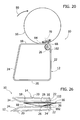
- Figures 18 to 23 and 24 to 29 illustrate, in side view and in plan view respectively, the sequence of opening of the piece of furniture of this second embodiment of the invention.
- the resting element 16 in the closed configuration is situated between the legs 12, 14 and extends in a plane parallel to the planes containing the legs 12, 14.
- the resting element 16 is rotated upwards in the direction indicated by the arrow 86 in Figure 19 .
- the external body 90 of the rotary joint 38 rotates together with the resting element 16, but the internal body 92 of the rotary joint 38 remains immobile.
- the amplitude of the movement of rotation, during which the internal body 92 remains immobile is equal to the angular extension of the groove 98 ( Figure 17 ) of the internal body 92.
- the legs 12, 14 remain immobile, as illustrated in Figure 25 .
- the resting element 16 is turned through 90° about the axis 70.
- the legs 12, 14 remain immobile during this movement of the resting element 16.
- the resting element 16 is turned about the axis 84 until it comes to rest with the top branches 18 of the legs 12, 14, as illustrated in Figures 23 and 29 , which show the piece of furniture 10 in its open condition.
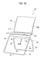
- Figures 30 to 41 illustrate a third embodiment of a piece of furniture according to the present invention.
- the piece of furniture 10 assumes the form of a chair including a first leg 12, a second leg 14, and a resting element 16 including a backrest 108 and a seat 110.
- the seat 110 is articulated to the backrest 108 about a transverse axis 111.
- Each leg 12, 14 comprises a top branch 18, a bottom branch 20, and two uprights 22, 24.
- the legs 12, 14 carry a first hub 26 and a second hub 28.
- the hubs 26, 28 are set at the centre of the respective top branches 18 of the legs 12, 14 and are preferably formed in a way integral with the respective legs.
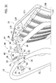
- the hubs 26, 28 have respective cam surfaces 30, 31 and respective through holes 32.
- the hubs 26, 28 have respective pins 48 projecting from the cam surfaces 30 eccentric with respect to the respective central hole 32.
- a rotary joint 38 is connected in a rotatable way to the first hub 26 and to the second hub 28.
- the rotary joint 38 has a body 40 with two plane cam surfaces 42, 44 contained in respective non-parallel planes.
- the cam surfaces 42, 44 are constantly parallel and set facing the cam surfaces 30, 31 of the hubs 26, 28.
- Formed on the cam surface 42 are a central hole 46 and an arched groove 36.
- the arched groove 36 is engaged by the pin 48 projecting from the cam surface 30 of the hub 26.
- the rotary joint 40 is connected to the first hub 26 by means of a pin 58.
- the pin 58 has a head 60, a first cylindrical portion 62, and a second cylindrical portion 64.
- the first cylindrical portion 62 engages in a rotatable way the hole 32 about an axis 34.
- the second cylindrical portion 64 is fixed in the hole 46 of the body 40.
- the axis 34 is orthogonal to the cam surfaces 30, 42.
- the body 40 of the rotary joint 38 has an integral shaft 112 projecting from the cam surface 44.
- the shaft 112 has a circular portion 114 and a hexagonal portion 116.
- the circular portion 114 engages in a rotatable way the hole 32 of the hub 28.
- the hexagonal portion 116 is fixed in a hexagonal hole 118 formed in a body 120 formed integrally in a bottom edge of the backrest 108.
- the connection between the shaft 112 and the body 120 performs the same function as the pin 58.
- the rotary joint 38 is connected in a rotatable way to the hubs 26, 28 about two axes 34, 35 inclined and incident with respect to one another.
- the cam surfaces 30, 31 of the hubs 26, 28 are constantly parallel to the cam surfaces 42, 44 of the body 40.
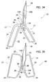
- Figures 32 to 36 and 37 to 41 illustrate, respectively, in lateral views and in top plan views, the sequence for bringing the piece of furniture 10 of this third embodiment from the closed condition to the open condition.
- the second leg 14 is set between the first leg 12 and the backrest 108.
- the seat 110 is folded against the backrest 108.
- the resting element 16 (including the backrest 108 and the seat 110) is turned through 180°.
- the rotary joint 38 turns in a way fixed with respect to the resting element 16.
- the contact between the cam surfaces set facing one another 42, 30 and 44, 31 of the rotary joint 38 and of the hubs 26, 28 causes a movement of the legs from a closed condition to a divaricated condition.
- Figures 33, 38 and 34, 39 illustrate two intermediate steps of the movement of rotation of the resting element 16.
- Figures 35 and 40 show the piece of furniture 10 at the end of the movement of rotation through 180° of the resting element 16.
- the end-of-travel positions of the resting element in a raised position and in a lowered position are defined by the end-of-travel positions of the pins 48 in the respective arched grooves 36.
- the legs 12, 14 are substantially contained in respective inclined planes converging upwards.
- the bottom branches 20 of the legs 12, 14 are parallel and set at a distance from one another in a longitudinal direction.
- the seat 110 is turned downwards until it comes to rest with its top part of the legs 12, 14, as illustrated in Figures 36 and 41 .
Landscapes
- Furniture Connections (AREA)
- Combinations Of Kitchen Furniture (AREA)
Priority Applications (2)
| Application Number | Priority Date | Filing Date | Title |
|---|---|---|---|
| AT09425192T ATE555688T1 (de) | 2009-05-20 | 2009-05-20 | Faltbares möbelstück |
| EP09425192A EP2253247B1 (fr) | 2009-05-20 | 2009-05-20 | Élément pliant de mobilier |
Applications Claiming Priority (1)
| Application Number | Priority Date | Filing Date | Title |
|---|---|---|---|
| EP09425192A EP2253247B1 (fr) | 2009-05-20 | 2009-05-20 | Élément pliant de mobilier |
Publications (2)
| Publication Number | Publication Date |
|---|---|
| EP2253247A1 true EP2253247A1 (fr) | 2010-11-24 |
| EP2253247B1 EP2253247B1 (fr) | 2012-05-02 |
Family
ID=41202512
Family Applications (1)
| Application Number | Title | Priority Date | Filing Date |
|---|---|---|---|
| EP09425192A Not-in-force EP2253247B1 (fr) | 2009-05-20 | 2009-05-20 | Élément pliant de mobilier |
Country Status (2)
| Country | Link |
|---|---|
| EP (1) | EP2253247B1 (fr) |
| AT (1) | ATE555688T1 (fr) |
Citations (3)
| Publication number | Priority date | Publication date | Assignee | Title |
|---|---|---|---|---|
| DE3544815A1 (de) * | 1985-12-18 | 1987-06-19 | Sonja Bressmer | Zusammenklappbarer servierwagen |
| EP1287760A1 (fr) * | 2001-08-24 | 2003-03-05 | Dauphin Entwicklungs- u. Beteiligungs-GmbH | Table pliante |
| DE202006003762U1 (de) | 2006-03-08 | 2007-07-12 | WINI Büromöbel Georg Schmidt GmbH & Co. KG | Tisch |
-
2009
- 2009-05-20 EP EP09425192A patent/EP2253247B1/fr not_active Not-in-force
- 2009-05-20 AT AT09425192T patent/ATE555688T1/de active
Patent Citations (3)
| Publication number | Priority date | Publication date | Assignee | Title |
|---|---|---|---|---|
| DE3544815A1 (de) * | 1985-12-18 | 1987-06-19 | Sonja Bressmer | Zusammenklappbarer servierwagen |
| EP1287760A1 (fr) * | 2001-08-24 | 2003-03-05 | Dauphin Entwicklungs- u. Beteiligungs-GmbH | Table pliante |
| DE202006003762U1 (de) | 2006-03-08 | 2007-07-12 | WINI Büromöbel Georg Schmidt GmbH & Co. KG | Tisch |
Also Published As
| Publication number | Publication date |
|---|---|
| ATE555688T1 (de) | 2012-05-15 |
| EP2253247B1 (fr) | 2012-05-02 |
Similar Documents
| Publication | Publication Date | Title |
|---|---|---|
| JP6753576B2 (ja) | 折り畳み式椅子 | |
| JP5188832B2 (ja) | 重ね合わせ可能な折り畳み式のテーブル | |
| JP2018518224A5 (fr) | ||
| CN102858205B (zh) | 锁止配件 | |
| TW201200739A (en) | Ceiling fan | |
| CN103518028A (zh) | 铰链 | |
| FR2824460A1 (fr) | Parc pour enfant avec table de change | |
| JP3151941U (ja) | 折り畳みテーブル | |
| TW201642928A (zh) | 訓練器 | |
| KR101317146B1 (ko) | 테이블 상판의 각도조절장치 | |
| EP2253247B1 (fr) | Élément pliant de mobilier | |
| US7017869B2 (en) | Tilting support device having damping device | |
| CN106122311B (zh) | 一种双向驱动装置、具有该装置的调高器和座椅 | |
| CN108721905A (zh) | 一种玩具的胯部关节结构 | |
| WO2018150447A1 (fr) | Fermoir de support de couplage | |
| EP2374375A1 (fr) | Chaise-lit | |
| KR200499544Y1 (ko) | 원터치 접이식 테이블 | |
| KR20230121019A (ko) | 스탠드형 네일 젤 램프장치 | |
| CN205409455U (zh) | 改良的莲花揉捻机结构 | |
| KR20190124611A (ko) | 저면공간의 확보가 가능한 접이식 탁구대 | |
| EP2770873A1 (fr) | Structure de support pour tables et table comprenant ladite structure de support | |
| JP2004527272A (ja) | リンク機構 | |
| US20140030006A1 (en) | Pivotal connection mechanism | |
| CN203506109U (zh) | 一种带活动件的可复位铰链 | |
| CA2785481C (fr) | Mecanisme de connexion a pivot |
Legal Events
| Date | Code | Title | Description |
|---|---|---|---|
| PUAI | Public reference made under article 153(3) epc to a published international application that has entered the european phase |
Free format text: ORIGINAL CODE: 0009012 |
|
| AK | Designated contracting states |
Kind code of ref document: A1 Designated state(s): AT BE BG CH CY CZ DE DK EE ES FI FR GB GR HR HU IE IS IT LI LT LU LV MC MK MT NL NO PL PT RO SE SI SK TR |
|
| AX | Request for extension of the european patent |
Extension state: AL BA RS |
|
| 17P | Request for examination filed |
Effective date: 20110516 |
|
| 17Q | First examination report despatched |
Effective date: 20110531 |
|
| REG | Reference to a national code |
Ref country code: DE Ref legal event code: R079 Ref document number: 602009006756 Country of ref document: DE Free format text: PREVIOUS MAIN CLASS: A47C0004180000 Ipc: A47B0003080000 |
|
| GRAP | Despatch of communication of intention to grant a patent |
Free format text: ORIGINAL CODE: EPIDOSNIGR1 |
|
| RIC1 | Information provided on ipc code assigned before grant |
Ipc: A47B 3/08 20060101AFI20111114BHEP Ipc: A47C 4/20 20060101ALI20111114BHEP |
|
| GRAS | Grant fee paid |
Free format text: ORIGINAL CODE: EPIDOSNIGR3 |
|
| GRAA | (expected) grant |
Free format text: ORIGINAL CODE: 0009210 |
|
| AK | Designated contracting states |
Kind code of ref document: B1 Designated state(s): AT BE BG CH CY CZ DE DK EE ES FI FR GB GR HR HU IE IS IT LI LT LU LV MC MK MT NL NO PL PT RO SE SI SK TR |
|
| REG | Reference to a national code |
Ref country code: GB Ref legal event code: FG4D |
|
| REG | Reference to a national code |
Ref country code: AT Ref legal event code: REF Ref document number: 555688 Country of ref document: AT Kind code of ref document: T Effective date: 20120515 Ref country code: CH Ref legal event code: EP |
|
| REG | Reference to a national code |
Ref country code: IE Ref legal event code: FG4D |
|
| REG | Reference to a national code |
Ref country code: DE Ref legal event code: R096 Ref document number: 602009006756 Country of ref document: DE Effective date: 20120621 |
|
| REG | Reference to a national code |
Ref country code: NL Ref legal event code: VDEP Effective date: 20120502 |
|
| REG | Reference to a national code |
Ref country code: LT Ref legal event code: MG4D Effective date: 20120502 |
|
| PG25 | Lapsed in a contracting state [announced via postgrant information from national office to epo] |
Ref country code: PL Free format text: LAPSE BECAUSE OF FAILURE TO SUBMIT A TRANSLATION OF THE DESCRIPTION OR TO PAY THE FEE WITHIN THE PRESCRIBED TIME-LIMIT Effective date: 20120502 Ref country code: LT Free format text: LAPSE BECAUSE OF FAILURE TO SUBMIT A TRANSLATION OF THE DESCRIPTION OR TO PAY THE FEE WITHIN THE PRESCRIBED TIME-LIMIT Effective date: 20120502 Ref country code: NO Free format text: LAPSE BECAUSE OF FAILURE TO SUBMIT A TRANSLATION OF THE DESCRIPTION OR TO PAY THE FEE WITHIN THE PRESCRIBED TIME-LIMIT Effective date: 20120802 Ref country code: SE Free format text: LAPSE BECAUSE OF FAILURE TO SUBMIT A TRANSLATION OF THE DESCRIPTION OR TO PAY THE FEE WITHIN THE PRESCRIBED TIME-LIMIT Effective date: 20120502 Ref country code: CY Free format text: LAPSE BECAUSE OF FAILURE TO SUBMIT A TRANSLATION OF THE DESCRIPTION OR TO PAY THE FEE WITHIN THE PRESCRIBED TIME-LIMIT Effective date: 20120502 Ref country code: IS Free format text: LAPSE BECAUSE OF FAILURE TO SUBMIT A TRANSLATION OF THE DESCRIPTION OR TO PAY THE FEE WITHIN THE PRESCRIBED TIME-LIMIT Effective date: 20120902 Ref country code: FI Free format text: LAPSE BECAUSE OF FAILURE TO SUBMIT A TRANSLATION OF THE DESCRIPTION OR TO PAY THE FEE WITHIN THE PRESCRIBED TIME-LIMIT Effective date: 20120502 |
|
| REG | Reference to a national code |
Ref country code: AT Ref legal event code: MK05 Ref document number: 555688 Country of ref document: AT Kind code of ref document: T Effective date: 20120502 |
|
| PG25 | Lapsed in a contracting state [announced via postgrant information from national office to epo] |
Ref country code: PT Free format text: LAPSE BECAUSE OF FAILURE TO SUBMIT A TRANSLATION OF THE DESCRIPTION OR TO PAY THE FEE WITHIN THE PRESCRIBED TIME-LIMIT Effective date: 20120903 Ref country code: LV Free format text: LAPSE BECAUSE OF FAILURE TO SUBMIT A TRANSLATION OF THE DESCRIPTION OR TO PAY THE FEE WITHIN THE PRESCRIBED TIME-LIMIT Effective date: 20120502 Ref country code: HR Free format text: LAPSE BECAUSE OF FAILURE TO SUBMIT A TRANSLATION OF THE DESCRIPTION OR TO PAY THE FEE WITHIN THE PRESCRIBED TIME-LIMIT Effective date: 20120502 Ref country code: SI Free format text: LAPSE BECAUSE OF FAILURE TO SUBMIT A TRANSLATION OF THE DESCRIPTION OR TO PAY THE FEE WITHIN THE PRESCRIBED TIME-LIMIT Effective date: 20120502 Ref country code: GR Free format text: LAPSE BECAUSE OF FAILURE TO SUBMIT A TRANSLATION OF THE DESCRIPTION OR TO PAY THE FEE WITHIN THE PRESCRIBED TIME-LIMIT Effective date: 20120803 |
|
| PG25 | Lapsed in a contracting state [announced via postgrant information from national office to epo] |
Ref country code: BE Free format text: LAPSE BECAUSE OF FAILURE TO SUBMIT A TRANSLATION OF THE DESCRIPTION OR TO PAY THE FEE WITHIN THE PRESCRIBED TIME-LIMIT Effective date: 20120502 Ref country code: MC Free format text: LAPSE BECAUSE OF NON-PAYMENT OF DUE FEES Effective date: 20120531 |
|
| PG25 | Lapsed in a contracting state [announced via postgrant information from national office to epo] |
Ref country code: AT Free format text: LAPSE BECAUSE OF FAILURE TO SUBMIT A TRANSLATION OF THE DESCRIPTION OR TO PAY THE FEE WITHIN THE PRESCRIBED TIME-LIMIT Effective date: 20120502 Ref country code: EE Free format text: LAPSE BECAUSE OF FAILURE TO SUBMIT A TRANSLATION OF THE DESCRIPTION OR TO PAY THE FEE WITHIN THE PRESCRIBED TIME-LIMIT Effective date: 20120502 Ref country code: DK Free format text: LAPSE BECAUSE OF FAILURE TO SUBMIT A TRANSLATION OF THE DESCRIPTION OR TO PAY THE FEE WITHIN THE PRESCRIBED TIME-LIMIT Effective date: 20120502 Ref country code: CZ Free format text: LAPSE BECAUSE OF FAILURE TO SUBMIT A TRANSLATION OF THE DESCRIPTION OR TO PAY THE FEE WITHIN THE PRESCRIBED TIME-LIMIT Effective date: 20120502 Ref country code: SK Free format text: LAPSE BECAUSE OF FAILURE TO SUBMIT A TRANSLATION OF THE DESCRIPTION OR TO PAY THE FEE WITHIN THE PRESCRIBED TIME-LIMIT Effective date: 20120502 Ref country code: NL Free format text: LAPSE BECAUSE OF FAILURE TO SUBMIT A TRANSLATION OF THE DESCRIPTION OR TO PAY THE FEE WITHIN THE PRESCRIBED TIME-LIMIT Effective date: 20120502 Ref country code: RO Free format text: LAPSE BECAUSE OF FAILURE TO SUBMIT A TRANSLATION OF THE DESCRIPTION OR TO PAY THE FEE WITHIN THE PRESCRIBED TIME-LIMIT Effective date: 20120502 |
|
| REG | Reference to a national code |
Ref country code: IE Ref legal event code: MM4A |
|
| PG25 | Lapsed in a contracting state [announced via postgrant information from national office to epo] |
Ref country code: MK Free format text: LAPSE BECAUSE OF FAILURE TO SUBMIT A TRANSLATION OF THE DESCRIPTION OR TO PAY THE FEE WITHIN THE PRESCRIBED TIME-LIMIT Effective date: 20120502 |
|
| PLBE | No opposition filed within time limit |
Free format text: ORIGINAL CODE: 0009261 |
|
| STAA | Information on the status of an ep patent application or granted ep patent |
Free format text: STATUS: NO OPPOSITION FILED WITHIN TIME LIMIT |
|
| REG | Reference to a national code |
Ref country code: DE Ref legal event code: R119 Ref document number: 602009006756 Country of ref document: DE Effective date: 20121201 |
|
| REG | Reference to a national code |
Ref country code: FR Ref legal event code: ST Effective date: 20130307 |
|
| 26N | No opposition filed |
Effective date: 20130205 |
|
| PG25 | Lapsed in a contracting state [announced via postgrant information from national office to epo] |
Ref country code: IE Free format text: LAPSE BECAUSE OF NON-PAYMENT OF DUE FEES Effective date: 20120520 Ref country code: ES Free format text: LAPSE BECAUSE OF FAILURE TO SUBMIT A TRANSLATION OF THE DESCRIPTION OR TO PAY THE FEE WITHIN THE PRESCRIBED TIME-LIMIT Effective date: 20120813 Ref country code: FR Free format text: LAPSE BECAUSE OF NON-PAYMENT OF DUE FEES Effective date: 20120702 |
|
| PG25 | Lapsed in a contracting state [announced via postgrant information from national office to epo] |
Ref country code: DE Free format text: LAPSE BECAUSE OF NON-PAYMENT OF DUE FEES Effective date: 20121201 |
|
| PG25 | Lapsed in a contracting state [announced via postgrant information from national office to epo] |
Ref country code: BG Free format text: LAPSE BECAUSE OF FAILURE TO SUBMIT A TRANSLATION OF THE DESCRIPTION OR TO PAY THE FEE WITHIN THE PRESCRIBED TIME-LIMIT Effective date: 20120802 Ref country code: MT Free format text: LAPSE BECAUSE OF FAILURE TO SUBMIT A TRANSLATION OF THE DESCRIPTION OR TO PAY THE FEE WITHIN THE PRESCRIBED TIME-LIMIT Effective date: 20120502 |
|
| PGFP | Annual fee paid to national office [announced via postgrant information from national office to epo] |
Ref country code: IT Payment date: 20130513 Year of fee payment: 5 |
|
| REG | Reference to a national code |
Ref country code: CH Ref legal event code: PL |
|
| GBPC | Gb: european patent ceased through non-payment of renewal fee |
Effective date: 20130520 |
|
| PG25 | Lapsed in a contracting state [announced via postgrant information from national office to epo] |
Ref country code: LI Free format text: LAPSE BECAUSE OF NON-PAYMENT OF DUE FEES Effective date: 20130531 Ref country code: CH Free format text: LAPSE BECAUSE OF NON-PAYMENT OF DUE FEES Effective date: 20130531 |
|
| PG25 | Lapsed in a contracting state [announced via postgrant information from national office to epo] |
Ref country code: TR Free format text: LAPSE BECAUSE OF FAILURE TO SUBMIT A TRANSLATION OF THE DESCRIPTION OR TO PAY THE FEE WITHIN THE PRESCRIBED TIME-LIMIT Effective date: 20120502 Ref country code: GB Free format text: LAPSE BECAUSE OF NON-PAYMENT OF DUE FEES Effective date: 20130520 |
|
| PG25 | Lapsed in a contracting state [announced via postgrant information from national office to epo] |
Ref country code: LU Free format text: LAPSE BECAUSE OF NON-PAYMENT OF DUE FEES Effective date: 20120520 |
|
| PG25 | Lapsed in a contracting state [announced via postgrant information from national office to epo] |
Ref country code: HU Free format text: LAPSE BECAUSE OF FAILURE TO SUBMIT A TRANSLATION OF THE DESCRIPTION OR TO PAY THE FEE WITHIN THE PRESCRIBED TIME-LIMIT Effective date: 20090520 |
|
| PG25 | Lapsed in a contracting state [announced via postgrant information from national office to epo] |
Ref country code: IT Free format text: LAPSE BECAUSE OF NON-PAYMENT OF DUE FEES Effective date: 20140520 |