EP2253382A2 - Vorrichtung zum Halten einer Filterfolie oder eines Filtertuches - Google Patents
Vorrichtung zum Halten einer Filterfolie oder eines Filtertuches Download PDFInfo
- Publication number
- EP2253382A2 EP2253382A2 EP10006128A EP10006128A EP2253382A2 EP 2253382 A2 EP2253382 A2 EP 2253382A2 EP 10006128 A EP10006128 A EP 10006128A EP 10006128 A EP10006128 A EP 10006128A EP 2253382 A2 EP2253382 A2 EP 2253382A2
- Authority
- EP
- European Patent Office
- Prior art keywords
- protective screen
- filter
- filter cloth
- protective
- screen
- Prior art date
- Legal status (The legal status is an assumption and is not a legal conclusion. Google has not performed a legal analysis and makes no representation as to the accuracy of the status listed.)
- Granted
Links
Images

Classifications
-
- B—PERFORMING OPERATIONS; TRANSPORTING
- B04—CENTRIFUGAL APPARATUS OR MACHINES FOR CARRYING-OUT PHYSICAL OR CHEMICAL PROCESSES
- B04B—CENTRIFUGES
- B04B7/00—Elements of centrifuges
- B04B7/08—Rotary bowls
- B04B7/12—Inserts, e.g. armouring plates
- B04B7/16—Sieves or filters
-
- B—PERFORMING OPERATIONS; TRANSPORTING
- B04—CENTRIFUGAL APPARATUS OR MACHINES FOR CARRYING-OUT PHYSICAL OR CHEMICAL PROCESSES
- B04B—CENTRIFUGES
- B04B7/00—Elements of centrifuges
- B04B7/08—Rotary bowls
- B04B7/18—Rotary bowls formed or coated with sieving or filtering elements
Definitions
- the present invention relates to a device for holding a filter film or a filter cloth, which rests in the installed state in a centrifuge drum on a support means, in particular a support screen, with a protective screen and with a sealing element with sealing lips, between which in the installed state itself extending the edges of the support means and the filter foil or the filter cloth, wherein in the installed state, the protective sieve clamps the filter foil or the filter cloth and the support means between the sealing lips of the sealing element.
- Filtration devices for the separation of microfine solids from suspensions are formed in many forms as centrifuges.
- filter elements with adequate retention are required.
- filter films or filter cloths are used. These filter sheets or filter cloths are usually placed on support means, in particular on support screens.
- a thickening layer of the retained solid particles forms on the filter films or filter cloths, which must be removed at appropriate time intervals.
- the scraper or the knife for discharging or discharging the solid layer can not be moved up to the filter film or the filter cloth to avoid damage, but also because, for example, folds in the cloth do not allow this.
- a bias voltage is applied in the radial direction with the aid of the protective screen, so that the edges of the support screen and the filter foil or the filter cloth are securely fixed between the sealing lips of the sealing element.
- the corresponding Andschreibsky is reinforced in the operating condition by the centrifugal force.
- the filter film or the filter cloth is fixed on the entire surface properly on the support screen, and the latter is pressed under this bias to the drum shell.
- the invention has for its object to provide a device for holding a filter foil or a filter cloth of the specified type, with which the filter foil or the filter cloth is kept particularly secure.
- the device further comprises at least one clamping ring which presses the protective screen radially outward in the installed state and that the protective screen is provided on its inside with at least one projection of the installed Clamping ring fixed in the axial direction.
- At least one clamping ring use that presses the protective screen radially outward in the installed state and thus against the two sealing elements at the edges of the filter film and the filter cloth suppressed. These are thereby brought to rest on the inner surface of the drum shell, and the edges of the support screen and filter foil or filter cloth are securely fixed between the sealing lips of the sealing elements.
- the invention provides that the protective screen has on its inside at least one projection which fixes the installed clamping ring in the axial direction.
- the latter has at least one clamping ring which can be arranged in the axially middle region of the protective screen.
- This clamping ring can move or move in both axial directions, so that here projections on both sides of the clamping ring are arranged on the protective screen.
- clamping rings used in the invention are known as such and of conventional design. They may preferably have a round, square or flat cross section and are preferably formed in two parts, d. H. have two turnbuckles, which mesh with a left-handed and a right-hand thread, so that in this way a tightening can be done without problems. It is understood that of course other embodiments of clamping rings can be used.
- inventively provided clamping rings is not specified.
- a single clamping ring can be used, which is preferably arranged axially in the middle.
- two clamping rings are provided, each of which is disposed in an axial end portion of the protective screen. But it can also be used more than two clamping rings, which are arranged at intervals over the axial length of the protective screen could be.
- the protective screen is provided on its inside with corresponding projections to prevent axial movement of the clamping rings.
- the projection on the inside of the protective screen is formed by a structuring or profiling thereof. In this embodiment, therefore, the projection is generated by a deformation of the protective screen.
- the projection is formed by a cam. This cam can for example be welded, screwed, riveted or glued.
- cam here not only punctiform protruding sections, but also strip-shaped projecting sections are meant.
- the projection may extend around the entire circumference of the protective screen or only part of it.
- the projection is formed by a bent-back edge tabs of the protective screen.
- This edge tab can be bent back for example by 90 ° or by 180 °.
- Such a marginal lobe can be easily produced by two adjacent slots made on the edge of the protective screen and the area located therebetween is bent back by the desired angle.
- the bent back Condition forms the corresponding tab then the corresponding axial fixation for the clamping ring.
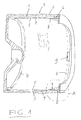
- centrifuge drum 1 has a drum shell 2, on the inside of a support screen 3, a filter cloth 4 and a protective screen 5 are arranged (in FIG. 2 shown on a larger scale).
- the support wire 3 rests on the inside of the drum shell 2, on which the filter cloth 8 lies tightly against.
- the protective screen 5, which has corresponding passage openings is pressed by bias against the filter cloth 4 so that it rests firmly on the support screen 3.
- FIG. 2 the support screen 3, the filter cloth 4 and the protective screen 5 are shown in the unstressed state for a better understanding. In operation, however, all parts are close together.
- the support wire 3 and the filter cloth 4 are held in two annular sealing elements 6, which are arranged in the region of the bottom and the lid of the centrifuge drum.
- clamping rings 7 are arranged on the inside of the protective screen 5, which rest on the axial edge regions of the protective screen, d. H. are arranged on the bottom and on the lid of the centrifuge drum.
- the clamping rings 7 are formed in two parts and each have two turnbuckles 9, with which they are braced while exerting a radial pressure on the protective sieve 5.
Landscapes
- Centrifugal Separators (AREA)
Abstract
Description
- Die vorliegende Erfindung betrifft einer Vorrichtung zum Halten einer Filterfolie oder eines Filtertuches, die bzw. das im installierten Zustand in einer Zentrifugentrommel auf einer Stützeinrichtung, insbesondere einem Stützsieb, aufliegt, mit einem Schutzsieb und mit einem Dichtelement mit Dichtlippen, zwischen denen im installierten Zustand sich die Ränder der Stützeinrichtung und der Filterfolie oder des Filtertuches erstrecken, wobei im installierten Zustand das Schutzsieb die Filterfolie oder das Filtertuch und die Stützeinrichtung zwischen den Dichtlippen des Dichtelementes festklemmt.
- Filtrationseinrichtungen zum Abscheiden von mikrofeinen Feststoffanteilen aus Suspensionen werden in vielfältiger Form als Zentrifugen ausgebildet. Zum Abtrennen der mikrofeinen Feststoffanteile, wie sie typischerweise in Suspensionen bei chemischen Prozessen anfallen, sind Filterelemente mit entsprechendem Rückhaltevermögen erforderlich. Hierzu werden überwiegend auswechselbare Filterfolien oder Filtertücher verwendet. Diese Filterfolien bzw. Filtertücher sind normalerweise auf Stützeinrichtungen, insbesondere auf Stützsieben, aufgelegt.
- Auf den Filterfolien bzw. Filtertüchern bildet sich im Betrieb eine dicker werdende Schicht aus den zurückgehaltenen Feststoffpartikeln, die in entsprechenden Zeitabständen abgetragen werden muss. Dabei können der Schaber bzw. die Messer zum Ab- bzw. Austragen der Feststoffschicht nicht bis ganz an die Filterfolie bzw. das Filtertuch herangefahren werden, um Beschädigungen zu vermeiden, aber auch, weil beispielsweise Falten im Tuch dies nicht zulassen.
- Die Befestigung der Filterfolie bzw. des Filtertuches erfolgt beispielsweise über Spannrahmen oder Spannringe mit Schrauben oder Nuten, in denen das Filtertuch gehalten wird. Insbesondere bei Zentrifugen, bei denen die Filterfolie bzw. das Filtertuch in der Trommel auf einem Stützsieb aufliegt, sind die Filtertuchbefestigungen herstellungsmäßig schwierig und teuer. Zur Lösung dieses Problems ist aus der
DE 39 16 383 C2 eine Vorrichtung zum Halten von Filterfolien oder Filtertüchern bekannt geworden, die am Anfang dieser Beschreibung erläutert ist. Diese Vorrichtung weist ein Schutzsieb auf, durch das eine Beschädigung der Filterfolie oder des Filtertuches beim Abtragen oder Ausräumen der Feststoffschicht sicher vermieden wird. Es ist dabei möglich, diese Schicht nahezu vollständig abzutragen, da der Schaber bzw. die Messer bis auf das Schutzsieb herangefahren werden können. Darüber hinaus wird mit Hilfe des Schutzsiebes in radialer Richtung eine Vorspannung aufgebracht, so dass die Ränder des Stützsiebes und der Filterfolie oder des Filtertuches sicher zwischen den Dichtlippen des Dichtelementes fixiert werden. Der entsprechende Andrückeffekt wird im Betriebszustand durch die Fliehkraft verstärkt. Die Filterfolie bzw. das Filtertuch wird auf der gesamten Fläche einwandfrei auf dem Stützsieb fixiert, und letzteres wird unter dieser Vorspannung an den Trommelmantel gepresst. - Die bekannte Vorrichtung hat sich im Betrieb bewährt. Zur Erzeugung der für eine vollständige Auflage auf dem Filtertuch ausreichenden Vorspannung weist das Schutzsieb einen an sich bekannten Steckverschluss auf. Für diesen Steckverschluss sind die radialen Ränder des Schutzsiebes mit Schlitzen bzw. Einschnitten versehen, die ineinander geschoben werden und damit das Schutzsieb unter Spannung setzen. Diese Spannung drückt bereits im Stillstand das Schutzsieb auf die Dichtelemente, bringt diese zur Anlage auf der Innenfläche des Trommelmantels und hält die Ränder von Stützsieb und Filterfolie bzw. Filtertuch zwischen den Dichtlippen sicher fest.
- Bei Zentrifugentrommeln, die mit hohen Drehzahlen arbeiten, ist die auf diese Weise mit dem Schutzsieb erzeugte Vorspannung völlig ausreichend. Es ergeben sich jedoch immer mehr Anwendungsbereiche für derartige Zentrifugen, bei denen mit relativ niedrigen Drehzahlen gearbeitet werden muss, um eine schonende Behandlung des zu filtrierenden Materiales zu ermöglichen. Hierbei besteht die Gefahr, dass die auf die vorstehend geschilderte Weise mit dem Schutzsieb aufgebrachte Vorspannung zum Fixieren der Filterfolie bzw. des Filtertuches nicht ausreicht, um die Filterfolie bzw. das Filtertuch sicher zu fixieren. Die Filterfolie bzw. das Filtertuch kann sich daher in Betrieb lösen, was zu Beschädigungen mit entsprechenden Stillliegezeiten und Reparaturarbeiten führen kann.
- Der Erfindung liegt die Aufgabe zugrunde, eine Vorrichtung zum Halten einer Filterfolie oder eines Filtertuches der angegebenen Art zu schaffen, mit der die Filterfolie oder das Filtertuch besonders sicher gehalten wird.
- Diese Aufgabe wird erfindungsgemäß bei einer Vorrichtung der eingangs beschriebenen Art dadurch gelöst, dass die Vorrichtung ferner mindestens einem Spannring aufweist, der im installierten Zustand das Schutzsieb radial nach außen presst und dass das Schutzsieb auf seiner Innenseite mit mindestens einem Vorsprung versehen ist, der den installierten Spannring in Axialrichtung fixiert.
- Bei der erfindungsgemäßen Vorrichtung findet somit zusätzlich zu einem Schutzsieb, mit dem eine radiale Vorspannung aufgebracht werden kann, mindestens ein Spannring Verwendung, der im installierten Zustand das Schutzsieb radial nach außen presst und damit gegen die beiden Dichtelemente an den Rändern der Filterfolie bzw. des Filtertuches drückt. Diese werden hierdurch zur Anlage auf der Innenfläche des Trommelmantels gebracht, und die Ränder von Stützsieb und Filterfolie bzw. Filtertuch werden zwischen den Dichtlippen der Dichtelemente sicher fixiert.
- Es ist zwar bekannt, Filterfolien bzw. Filtertücher mit Hilfe von Spannrahmen und Spannringen mit Schrauben oder Nuten, in denen die Filterfolie bzw. das Filtertuch gehalten wird, zu befestigen. Nicht bekannt ist es jedoch, derartige Spannringe in Verbindung mit Sieben einzusetzen, um auf diese Weise die von den Schutzsieben aufgebrachte Vorspannung zu erhöhen und eine noch bessere Fixierung der Filterfolie bzw. des Filtertuches und/oder der Stützeinrichtung, insbesondere des Stützsiebes, zu erreichen.
- Überraschenderweise wurde festgestellt, dass bei Anordnung eines derartigen Spannringes an der Innenseite des Schutzsiebes die Gefahr besteht, dass sich der Spannring im Betrieb in Axialrichtung verschieben kann. Dies ist natürlich unerwünscht, da hierdurch die Funktionsweise der Zentrifugentrommel beeinträchtigt wird, insbesondere die Gefahr besteht, dass der Schaber bzw. die Messer mit dem Spannring kollidieren. Bei der Anordnung eines derartigen Spannringes ist der Schaber bzw. sind die Messer vorzugsweise an der entsprechenden Stelle ausgenommen, so dass sich keine unerwünschten Kontakte ergeben. Um eine derartige Axialverschiebung des Spannringes zu verhindern, ist erfindungsgemäß vorgesehen, dass das Schutzsieb auf seiner Innenseite mindestens einen Vorsprung aufweist, der den installierten Spannring in Axialrichtung fixiert.
- Vorzugsweise besitzt die Vorrichtung zwei Spannringe für die beiden axialen Endbereiche des Schutzsiebes und weist das Schutzsieb mindestens zwei Vorsprünge zur Verhinderung einer Axialverschiebung der Spannringe auf. Wenn die Spannringe in den Endbereichen des Schutzsiebes vorgesehen sind, ist es normalerweise ausreichend, eine Axialbewegung der Spannringe zur axialen Mitte des Schutzsiebes hin zu verhindern, so dass nur auf einer Seite (zur axialen Mitte des Schutzsiebes hin) des Spannringes mindestens ein entsprechender Vorsprung angeordnet sein muss.
- Bei einer anderen Ausführungsform der Vorrichtung weist diese mindestens einen im axial mittleren Bereich des Schutzsiebes anordbaren Spannring auf. Dieser Spannring kann sich in beiden axialen Richtungen bewegen bzw. verschieben, so dass hier Vorsprünge an beiden Seiten des Spannringes am Schutzsieb angeordnet sind.
- Die erfindungsgemäß verwendeten Spannringe sind als solche bekannt und von üblicher Bauart. Sie können vorzugsweise einen runden, quadratischen oder flachen Querschnitt besitzen und sind vorzugsweise zweiteilig ausgebildet, d. h. besitzen zwei Spannschlösser, die mit einem linksgängigen und einem rechtgängigen Gewinde kämmen, so dass auf diese Weise ein Verspannen unproblematisch erfolgen kann. Es versteht sich, dass natürlich auch andere Ausführungsformen von Spannringen Verwendung finden können.
- Die Anzahl der erfindungsgemäß vorgesehenen Spannringe ist nicht festgelegt. Im einfachsten Fall kann ein einziger Spannring Verwendung finden, der vorzugsweise axial mittig angeordnet ist. Bei einer anderen Ausführungsform sind zwei Spannringe vorgesehen, von denen jeder in einem axialen Endbereich des Schutzsiebes angeordnet ist. Es können aber auch mehr als zwei Spannringe Verwendung finden, welche in Abständen über die axiale Länge des Schutzsiebes angeordnet sein können. Je nach der Anzahl der vorgesehenen Spannringe ist das Schutzsieb auf seiner Innenseite mit entsprechenden Vorsprüngen versehen, um Axialbewegungen der Spannringe zu verhindern.
- Was die Ausbildung des mindestens einen Vorsprungs anbetrifft, so sind diverse Ausführungsformen möglich. Bei einer bevorzugten Ausführungsform ist der Vorsprung auf der Innenseite des Schutzsiebes von einer Strukturierung bzw. Profilierung desselben gebildet. Bei dieser Ausführungsform wird daher der Vorsprung durch eine Verformung des Schutzsiebes erzeugt. Bei einer anderen Ausführungsform ist der Vorsprung von einem Nocken gebildet. Dieser Nocken kann beispielsweise aufgeschweißt, aufgeschraubt, aufgenietet oder aufgeklebt sein. Mit "Nocken" sind hier nicht nur punktförmige vorstehende Abschnitte, sondern auch leistenförmige vorstehende Abschnitte gemeint.
- Der Vorsprung kann sich um den gesamten Umfang des Schutzsiebes oder nur um einen Teil desselben erstrecken.
- Bei einer besonders bevorzugten Ausführungsform der Erfindung, bei der der Spannring im axialen Endbereich des Schutzsiebes angeordnet ist, ist der Vorsprung von einem zurückgebogenen Randlappen des Schutzsiebes gebildet. Dieser Randlappen kann beispielsweise um 90° oder um 180° zurückgebogen sein. Ein solcher Randlappen lässt sich einfach herstellen, indem zwei benachbarte Schlitze am Rand des Schutzsiebes hergestellt und der dazwischen befindliche Bereich um den gewünschten Winkel zurückgebogen wird. Im zurückgebogenen Zustand bildet der entsprechende Lappen dann die entsprechende Axialfixierung für den Spannring.
- Die Erfindung wird nachfolgend anhand eines Ausführungsbeispiels in Verbindung mit der Zeichnung im Einzelnen erläutert. Es zeigen:
- Figur 1
- eine geschnittene Zentrifugentrommel in räumli- cher Darstellung;
- Figur 2
- ein Detail an der Stelle A in
Figur 1 ; und - Figur 3
- die Darstellung eines Randlappens zur axialen Fixierung eines Spannringes.
- Die in
Figur 1 dargestellte Zentrifugentrommel 1 weist einen Trommelmantel 2 auf, auf dessen Innenseite ein Stützsieb 3, ein Filtertuch 4 und ein Schutzsieb 5 angeordnet sind (inFigur 2 im größeren Maßstab gezeigt). Das Stützsieb 3 liegt auf der Innenseite des Trommelmantels 2 auf, darauf liegt das Filtertuch 8 dicht anliegend auf. Das Schutzsieb 5, das entsprechende Durchlassöffnungen aufweist, wird durch Vorspannung fest gegen das Filtertuch 4 gedrückt, so dass dieses fest auf dem Stützsieb 3 aufliegt. InFigur 2 sind das Stützsieb 3, das Filtertuch 4 und das Schutzsieb 5 zum besseren Verständnis im unverspannten Zustand dargestellt. Im Betriebszustand liegen jedoch alle Teile dicht aufeinander. Das Stützsieb 3 und das Filtertuch 4 werden in zwei ringförmigen Dichtelementen 6 gehalten, die im Bereich des Bodens und des Deckels der Zentrifugentrommel angeordnet sind. Die ringförmigen Dichtelemente 6 weisen drei Dichtlippen 10 auf, die zwei Kammern bilden, in denen die Ränder des Stützsiebes 3 und des Filtertuches 4 im flachgepressten Zustand angeordnet sind. Nach Einbau des Stützsiebes 3 und des Filtertuches 4 zusammen mit den Dichtelementen 6 wird das Schutzsieb 5 so eingelegt, dass es auf die inneren Flächen der Dichtelemente 6 drückt und auf dem Filtertuch unter Spannung aufliegt. - Zusätzlich sind an der Innenseite des Schutzsiebes 5 zwei Spannringe 7 angeordnet, welche auf den axialen Randbereichen des Schutzsiebes aufliegen, d. h. am Boden und am Deckel der Zentrifugentrommel angeordnet sind. Die Spannringe 7 sind zweiteilig ausgebildet und weisen jeweils zwei Spannschlösser 9 auf, mit denen sie verspannt werden und dabei einen radialen Druck auf das Schutzsieb 5 ausüben.
- Um eine axiale Bewegung der Spannringe 7 zur axialen Mitte der Zentrifugentrommel hin zu verhindern, sind über den Umfang des Schutzsiebes 5 verteilt mehrere Vorsprünge 8 in der Form von einwärts gebogenen Lappen vorgesehen, welche den zugehörigen Spannring 7 in Axialrichtung festlegen. Die Ausbildung dieser Lappen ist speziell in
Figur 3 gezeigt. Die Lappen werden hergestellt, indem ein Rand des zylindrischen Schutzsiebes 5 mit zwei benachbarten Schlitzen bzw. Einschnitten versehen und der dazwischen angeordnete Abschnitte des Schutzsiebes um 180° nach innen gebogen wird, so dass sich der inFigur 3 dargestellte lappenförmige Vorsprung 8 ergibt. Die hierdurch gebildete Ausnehmung am Rand des Schutzsiebes 5 ist mit 10 bezeichnet. Mehrere dieser lappenförmigen Vorsprünge 8, die über den Umfang des Schutzsiebes 5 verteilt sind, bilden die entsprechende Axialfixierung des Spannringes 7.
Claims (6)
- Vorrichtung zum Halten einer Filterfolie oder eines Filtertuches, die bzw. das im installierten Zustand in einer Zentrifugentrommel auf einer Stützeinrichtung, insbesondere einem Stützsieb, aufliegt, mit einem Schutzsieb und mit einem Dichtelement mit Dichtlippen, zwischen denen im installierten Zustand sich die Ränder der Stützeinrichtung und der Filterfolie oder des Filtertuchs erstrecken, wobei im installierten Zustand das Schutzsieb die Filterfolie oder das Filtertuch und die Stützeinrichtung zwischen den Dichtlippen des Dichtelementes festklemmt, dadurch gekennzeichnet, dass die Vorrichtung ferner mindestens einen Spannring (7) aufweist, der im installierten Zustand das Schutzsieb (5) radial nach außen presst, und dass das Schutzsieb (5) auf seiner Innenseite mit mindestens einem Vorsprung (8) versehen ist, der den installierten Spannring (7) in Axialrichtung fixiert.
- Vorrichtung nach Anspruch 1, dadurch gekennzeichnet, dass sie zwei Spannringe (7) für die beiden axialen Endbereiche des Schutzsiebes (5) besitzt und dass das Schutzsieb (5) mindestens zwei Vorsprünge (8) zur Axialfixierung der Spannringe (7) aufweist.
- Vorrichtung nach einem der vorangehenden Ansprüche, dadurch gekennzeichnet, dass sie mindestens einen im axial mittleren Bereich des Schutzsiebes anordbaren Spannring besitzt.
- Vorrichtung nach einem der vorangehenden Ansprüche, dadurch gekennzeichnet, dass der Vorsprung auf der Innenseite des Schutzsiebes von einer Strukturierung bzw. Profilierung desselben gebildet ist.
- Vorrichtung nach einem der Ansprüche 1 bis 3, dadurch gekennzeichnet, dass der Vorsprung von einem Nocken gebildet ist.
- Vorrichtung nach einem der Ansprüche 1 bis 3, dadurch gekennzeichnet, dass der Vorsprung (8) von einem zurückgebogenen Randlappen des Schutzsiebes (5) gebildet ist.
Applications Claiming Priority (1)
| Application Number | Priority Date | Filing Date | Title |
|---|---|---|---|
| DE102009024760A DE102009024760A1 (de) | 2009-06-13 | 2009-06-13 | Vorrichtung zum Halten einer Filterfolie oder eines Filtertuches |
Publications (4)
| Publication Number | Publication Date |
|---|---|
| EP2253382A2 true EP2253382A2 (de) | 2010-11-24 |
| EP2253382A8 EP2253382A8 (de) | 2011-03-02 |
| EP2253382A3 EP2253382A3 (de) | 2013-12-25 |
| EP2253382B1 EP2253382B1 (de) | 2016-12-14 |
Family
ID=42633076
Family Applications (1)
| Application Number | Title | Priority Date | Filing Date |
|---|---|---|---|
| EP10006128.2A Active EP2253382B1 (de) | 2009-06-13 | 2010-06-14 | Vorrichtung zum Halten einer Filterfolie oder eines Filtertuches |
Country Status (2)
| Country | Link |
|---|---|
| EP (1) | EP2253382B1 (de) |
| DE (1) | DE102009024760A1 (de) |
Cited By (3)
| Publication number | Priority date | Publication date | Assignee | Title |
|---|---|---|---|---|
| WO2014106669A1 (en) * | 2013-01-07 | 2014-07-10 | Clear Edge-Germany Gmbh | Filter cloth retention |
| DE102014119605A1 (de) * | 2014-12-23 | 2016-06-23 | Andritz Kmpt Gmbh | Filterzentrifuge |
| CN106694244A (zh) * | 2017-02-28 | 2017-05-24 | 蚌埠市兴利离心机制造有限公司 | 一种立式离心机的转鼓滤布撑箍结构 |
Families Citing this family (3)
| Publication number | Priority date | Publication date | Assignee | Title |
|---|---|---|---|---|
| DE102015005609A1 (de) | 2015-04-30 | 2016-11-03 | Guntram Krettek | Zentrifugentrommel und Filterpaket zum Einbau in eine Zentrifugentrommel |
| DE102015015014A1 (de) | 2015-11-19 | 2017-05-24 | Guntram Krettek | Zentrifugentrommel mit Befestigungsvorrichtung und Kniehebelschlossring |
| DE102018007294A1 (de) | 2018-09-14 | 2020-03-19 | Guntram Krettek | Verfahren zum Fixieren eines Bleches und damit hergestellte Filtereinrichtung |
Citations (1)
| Publication number | Priority date | Publication date | Assignee | Title |
|---|---|---|---|---|
| DE3916383C2 (de) | 1989-05-19 | 1999-01-07 | Guntram Krettek | Vorrichtung zum Halten von Filterfolien oder Filtertüchern |
Family Cites Families (2)
| Publication number | Priority date | Publication date | Assignee | Title |
|---|---|---|---|---|
| US1946500A (en) * | 1933-01-28 | 1934-02-13 | Western States Machine Co | Basket lining for centrifugals |
| JPH10180144A (ja) * | 1996-12-26 | 1998-07-07 | Mitsubishi Kakoki Kaisha Ltd | 遠心濾過機用濾材の固定金具 |
-
2009
- 2009-06-13 DE DE102009024760A patent/DE102009024760A1/de not_active Withdrawn
-
2010
- 2010-06-14 EP EP10006128.2A patent/EP2253382B1/de active Active
Patent Citations (1)
| Publication number | Priority date | Publication date | Assignee | Title |
|---|---|---|---|---|
| DE3916383C2 (de) | 1989-05-19 | 1999-01-07 | Guntram Krettek | Vorrichtung zum Halten von Filterfolien oder Filtertüchern |
Cited By (3)
| Publication number | Priority date | Publication date | Assignee | Title |
|---|---|---|---|---|
| WO2014106669A1 (en) * | 2013-01-07 | 2014-07-10 | Clear Edge-Germany Gmbh | Filter cloth retention |
| DE102014119605A1 (de) * | 2014-12-23 | 2016-06-23 | Andritz Kmpt Gmbh | Filterzentrifuge |
| CN106694244A (zh) * | 2017-02-28 | 2017-05-24 | 蚌埠市兴利离心机制造有限公司 | 一种立式离心机的转鼓滤布撑箍结构 |
Also Published As
| Publication number | Publication date |
|---|---|
| EP2253382B1 (de) | 2016-12-14 |
| DE102009024760A1 (de) | 2010-12-16 |
| EP2253382A3 (de) | 2013-12-25 |
| EP2253382A8 (de) | 2011-03-02 |
Similar Documents
| Publication | Publication Date | Title |
|---|---|---|
| EP2253382B1 (de) | Vorrichtung zum Halten einer Filterfolie oder eines Filtertuches | |
| DE102011001015B4 (de) | Filterelement für die Filtrierung eines Fluids und daraus gebildete Filtereinheit | |
| EP2907579B1 (de) | Zentrifugenkorb für eine Siebzentrifuge | |
| DE2826734A1 (de) | Filtersektor | |
| DE4119166C2 (de) | Filterelement für eine Filterpresse | |
| DE3113624A1 (de) | "rueckspuelbare filtriervorrichtung" | |
| WO2008148667A1 (de) | Verfahren zum filtern einer suspension und filtervorrichtung | |
| EP0398173B1 (de) | Filtrationseinrichtung mit einer Vorrichtung zum Halten von Filterelementen | |
| DE60002521T2 (de) | Siebzylinder, insbesondere für Papierfaserstoff | |
| DE69601075T2 (de) | Filtervorrichtung | |
| DE3102303A1 (de) | Siebtrommel, insbesondere fuer siebzentrifugen | |
| EP1825933A2 (de) | Verfahren zur Herstellung einer rotationssymmetrischen, insbesondere zylindrischen Siebvorrichtung | |
| EP0505518B1 (de) | Filterplatte für eine plattenfilterpresse | |
| EP4308264A1 (de) | Anordnung einer filterplatte für eine filterpresse und eines einsatzes sowie ringförmiger einsatz für eine filterplatte | |
| EP3107708A1 (de) | Vorrichtung zum filtrieren einer kunststoffschmelze | |
| EP0827766A1 (de) | Pressmembran für eine Membranplatte einer Plattenfilterpresse | |
| EP2481474B1 (de) | Dichtungsanordnung für stabförmige keramische Filterelemente | |
| EP3170563A1 (de) | Zentrifugentrommel mit befestigungsvorrichtung und kniehebelschlossring | |
| EP1694443B1 (de) | Verfahren zum befestigen eines siebeinsatzes in einer vibrationssiebmaschine und vibrationssiebmaschine für asphaltmischanlagen | |
| EP3501620A1 (de) | Stützring für die befestigung eines filtertuchs an einem filterelement | |
| DE102016008501B4 (de) | Mikrofilter zum Filtern von flüssigen oder gasförmigen Medien | |
| WO2016173576A2 (de) | Zentrifugentroirtmel und filterpaket zum einbau in eine zentrifugentrommel | |
| DE1965005A1 (de) | Siebvorrichtung | |
| EP1163943A1 (de) | Membranfilterplatte für eine Filterpresse sowie Trägerplatte und Membran für eine solche Membranfilterplatte | |
| DE102018007294A1 (de) | Verfahren zum Fixieren eines Bleches und damit hergestellte Filtereinrichtung |
Legal Events
| Date | Code | Title | Description |
|---|---|---|---|
| PUAI | Public reference made under article 153(3) epc to a published international application that has entered the european phase |
Free format text: ORIGINAL CODE: 0009012 |
|
| AK | Designated contracting states |
Kind code of ref document: A2 Designated state(s): AL AT BE BG CH CY CZ DE DK EE ES FI FR GB GR HR HU IE IS IT LI LT LU LV MC MK MT NL NO PL PT RO SE SI SK SM TR |
|
| AX | Request for extension of the european patent |
Extension state: BA ME RS |
|
| PUAL | Search report despatched |
Free format text: ORIGINAL CODE: 0009013 |
|
| AK | Designated contracting states |
Kind code of ref document: A3 Designated state(s): AL AT BE BG CH CY CZ DE DK EE ES FI FR GB GR HR HU IE IS IT LI LT LU LV MC MK MT NL NO PL PT RO SE SI SK SM TR |
|
| AX | Request for extension of the european patent |
Extension state: BA ME RS |
|
| RIC1 | Information provided on ipc code assigned before grant |
Ipc: B04B 7/16 20060101AFI20131119BHEP |
|
| 17P | Request for examination filed |
Effective date: 20140318 |
|
| RBV | Designated contracting states (corrected) |
Designated state(s): AL AT BE BG CH CY CZ DE DK EE ES FI FR GB GR HR HU IE IS IT LI LT LU LV MC MK MT NL NO PL PT RO SE SI SK SM TR |
|
| GRAP | Despatch of communication of intention to grant a patent |
Free format text: ORIGINAL CODE: EPIDOSNIGR1 |
|
| INTG | Intention to grant announced |
Effective date: 20160701 |
|
| STAA | Information on the status of an ep patent application or granted ep patent |
Free format text: STATUS: GRANT OF PATENT IS INTENDED |
|
| GRAS | Grant fee paid |
Free format text: ORIGINAL CODE: EPIDOSNIGR3 |
|
| GRAA | (expected) grant |
Free format text: ORIGINAL CODE: 0009210 |
|
| STAA | Information on the status of an ep patent application or granted ep patent |
Free format text: STATUS: THE PATENT HAS BEEN GRANTED |
|
| AK | Designated contracting states |
Kind code of ref document: B1 Designated state(s): AL AT BE BG CH CY CZ DE DK EE ES FI FR GB GR HR HU IE IS IT LI LT LU LV MC MK MT NL NO PL PT RO SE SI SK SM TR |
|
| REG | Reference to a national code |
Ref country code: GB Ref legal event code: FG4D Free format text: NOT ENGLISH |
|
| REG | Reference to a national code |
Ref country code: CH Ref legal event code: EP |
|
| REG | Reference to a national code |
Ref country code: IE Ref legal event code: FG4D Free format text: LANGUAGE OF EP DOCUMENT: GERMAN |
|
| REG | Reference to a national code |
Ref country code: AT Ref legal event code: REF Ref document number: 853090 Country of ref document: AT Kind code of ref document: T Effective date: 20170115 |
|
| REG | Reference to a national code |
Ref country code: DE Ref legal event code: R096 Ref document number: 502010012860 Country of ref document: DE |
|
| PG25 | Lapsed in a contracting state [announced via postgrant information from national office to epo] |
Ref country code: LV Free format text: LAPSE BECAUSE OF FAILURE TO SUBMIT A TRANSLATION OF THE DESCRIPTION OR TO PAY THE FEE WITHIN THE PRESCRIBED TIME-LIMIT Effective date: 20161214 |
|
| REG | Reference to a national code |
Ref country code: CH Ref legal event code: NV Representative=s name: HEPP WENGER RYFFEL AG, CH |
|
| REG | Reference to a national code |
Ref country code: LT Ref legal event code: MG4D |
|
| REG | Reference to a national code |
Ref country code: NL Ref legal event code: MP Effective date: 20161214 |
|
| PG25 | Lapsed in a contracting state [announced via postgrant information from national office to epo] |
Ref country code: LT Free format text: LAPSE BECAUSE OF FAILURE TO SUBMIT A TRANSLATION OF THE DESCRIPTION OR TO PAY THE FEE WITHIN THE PRESCRIBED TIME-LIMIT Effective date: 20161214 Ref country code: SE Free format text: LAPSE BECAUSE OF FAILURE TO SUBMIT A TRANSLATION OF THE DESCRIPTION OR TO PAY THE FEE WITHIN THE PRESCRIBED TIME-LIMIT Effective date: 20161214 Ref country code: GR Free format text: LAPSE BECAUSE OF FAILURE TO SUBMIT A TRANSLATION OF THE DESCRIPTION OR TO PAY THE FEE WITHIN THE PRESCRIBED TIME-LIMIT Effective date: 20170315 Ref country code: NO Free format text: LAPSE BECAUSE OF FAILURE TO SUBMIT A TRANSLATION OF THE DESCRIPTION OR TO PAY THE FEE WITHIN THE PRESCRIBED TIME-LIMIT Effective date: 20170314 |
|
| PG25 | Lapsed in a contracting state [announced via postgrant information from national office to epo] |
Ref country code: FI Free format text: LAPSE BECAUSE OF FAILURE TO SUBMIT A TRANSLATION OF THE DESCRIPTION OR TO PAY THE FEE WITHIN THE PRESCRIBED TIME-LIMIT Effective date: 20161214 Ref country code: HR Free format text: LAPSE BECAUSE OF FAILURE TO SUBMIT A TRANSLATION OF THE DESCRIPTION OR TO PAY THE FEE WITHIN THE PRESCRIBED TIME-LIMIT Effective date: 20161214 |
|
| REG | Reference to a national code |
Ref country code: FR Ref legal event code: PLFP Year of fee payment: 8 |
|
| PG25 | Lapsed in a contracting state [announced via postgrant information from national office to epo] |
Ref country code: NL Free format text: LAPSE BECAUSE OF FAILURE TO SUBMIT A TRANSLATION OF THE DESCRIPTION OR TO PAY THE FEE WITHIN THE PRESCRIBED TIME-LIMIT Effective date: 20161214 |
|
| PG25 | Lapsed in a contracting state [announced via postgrant information from national office to epo] |
Ref country code: RO Free format text: LAPSE BECAUSE OF FAILURE TO SUBMIT A TRANSLATION OF THE DESCRIPTION OR TO PAY THE FEE WITHIN THE PRESCRIBED TIME-LIMIT Effective date: 20161214 Ref country code: IS Free format text: LAPSE BECAUSE OF FAILURE TO SUBMIT A TRANSLATION OF THE DESCRIPTION OR TO PAY THE FEE WITHIN THE PRESCRIBED TIME-LIMIT Effective date: 20170414 Ref country code: EE Free format text: LAPSE BECAUSE OF FAILURE TO SUBMIT A TRANSLATION OF THE DESCRIPTION OR TO PAY THE FEE WITHIN THE PRESCRIBED TIME-LIMIT Effective date: 20161214 Ref country code: CZ Free format text: LAPSE BECAUSE OF FAILURE TO SUBMIT A TRANSLATION OF THE DESCRIPTION OR TO PAY THE FEE WITHIN THE PRESCRIBED TIME-LIMIT Effective date: 20161214 Ref country code: SK Free format text: LAPSE BECAUSE OF FAILURE TO SUBMIT A TRANSLATION OF THE DESCRIPTION OR TO PAY THE FEE WITHIN THE PRESCRIBED TIME-LIMIT Effective date: 20161214 |
|
| PG25 | Lapsed in a contracting state [announced via postgrant information from national office to epo] |
Ref country code: PT Free format text: LAPSE BECAUSE OF FAILURE TO SUBMIT A TRANSLATION OF THE DESCRIPTION OR TO PAY THE FEE WITHIN THE PRESCRIBED TIME-LIMIT Effective date: 20170414 Ref country code: BG Free format text: LAPSE BECAUSE OF FAILURE TO SUBMIT A TRANSLATION OF THE DESCRIPTION OR TO PAY THE FEE WITHIN THE PRESCRIBED TIME-LIMIT Effective date: 20170314 Ref country code: PL Free format text: LAPSE BECAUSE OF FAILURE TO SUBMIT A TRANSLATION OF THE DESCRIPTION OR TO PAY THE FEE WITHIN THE PRESCRIBED TIME-LIMIT Effective date: 20161214 Ref country code: SM Free format text: LAPSE BECAUSE OF FAILURE TO SUBMIT A TRANSLATION OF THE DESCRIPTION OR TO PAY THE FEE WITHIN THE PRESCRIBED TIME-LIMIT Effective date: 20161214 Ref country code: ES Free format text: LAPSE BECAUSE OF FAILURE TO SUBMIT A TRANSLATION OF THE DESCRIPTION OR TO PAY THE FEE WITHIN THE PRESCRIBED TIME-LIMIT Effective date: 20161214 |
|
| REG | Reference to a national code |
Ref country code: DE Ref legal event code: R097 Ref document number: 502010012860 Country of ref document: DE |
|
| PLBE | No opposition filed within time limit |
Free format text: ORIGINAL CODE: 0009261 |
|
| STAA | Information on the status of an ep patent application or granted ep patent |
Free format text: STATUS: NO OPPOSITION FILED WITHIN TIME LIMIT |
|
| 26N | No opposition filed |
Effective date: 20170915 |
|
| PG25 | Lapsed in a contracting state [announced via postgrant information from national office to epo] |
Ref country code: DK Free format text: LAPSE BECAUSE OF FAILURE TO SUBMIT A TRANSLATION OF THE DESCRIPTION OR TO PAY THE FEE WITHIN THE PRESCRIBED TIME-LIMIT Effective date: 20161214 |
|
| PG25 | Lapsed in a contracting state [announced via postgrant information from national office to epo] |
Ref country code: MC Free format text: LAPSE BECAUSE OF FAILURE TO SUBMIT A TRANSLATION OF THE DESCRIPTION OR TO PAY THE FEE WITHIN THE PRESCRIBED TIME-LIMIT Effective date: 20161214 |
|
| PG25 | Lapsed in a contracting state [announced via postgrant information from national office to epo] |
Ref country code: SI Free format text: LAPSE BECAUSE OF FAILURE TO SUBMIT A TRANSLATION OF THE DESCRIPTION OR TO PAY THE FEE WITHIN THE PRESCRIBED TIME-LIMIT Effective date: 20161214 |
|
| REG | Reference to a national code |
Ref country code: IE Ref legal event code: MM4A |
|
| PG25 | Lapsed in a contracting state [announced via postgrant information from national office to epo] |
Ref country code: LU Free format text: LAPSE BECAUSE OF NON-PAYMENT OF DUE FEES Effective date: 20170614 Ref country code: IE Free format text: LAPSE BECAUSE OF NON-PAYMENT OF DUE FEES Effective date: 20170614 |
|
| REG | Reference to a national code |
Ref country code: BE Ref legal event code: MM Effective date: 20170630 |
|
| REG | Reference to a national code |
Ref country code: FR Ref legal event code: PLFP Year of fee payment: 9 |
|
| PG25 | Lapsed in a contracting state [announced via postgrant information from national office to epo] |
Ref country code: BE Free format text: LAPSE BECAUSE OF NON-PAYMENT OF DUE FEES Effective date: 20170630 |
|
| PG25 | Lapsed in a contracting state [announced via postgrant information from national office to epo] |
Ref country code: MT Free format text: LAPSE BECAUSE OF FAILURE TO SUBMIT A TRANSLATION OF THE DESCRIPTION OR TO PAY THE FEE WITHIN THE PRESCRIBED TIME-LIMIT Effective date: 20161214 |
|
| PG25 | Lapsed in a contracting state [announced via postgrant information from national office to epo] |
Ref country code: HU Free format text: LAPSE BECAUSE OF FAILURE TO SUBMIT A TRANSLATION OF THE DESCRIPTION OR TO PAY THE FEE WITHIN THE PRESCRIBED TIME-LIMIT; INVALID AB INITIO Effective date: 20100614 |
|
| PG25 | Lapsed in a contracting state [announced via postgrant information from national office to epo] |
Ref country code: CY Free format text: LAPSE BECAUSE OF NON-PAYMENT OF DUE FEES Effective date: 20161214 |
|
| PG25 | Lapsed in a contracting state [announced via postgrant information from national office to epo] |
Ref country code: MK Free format text: LAPSE BECAUSE OF FAILURE TO SUBMIT A TRANSLATION OF THE DESCRIPTION OR TO PAY THE FEE WITHIN THE PRESCRIBED TIME-LIMIT Effective date: 20161214 |
|
| PG25 | Lapsed in a contracting state [announced via postgrant information from national office to epo] |
Ref country code: TR Free format text: LAPSE BECAUSE OF FAILURE TO SUBMIT A TRANSLATION OF THE DESCRIPTION OR TO PAY THE FEE WITHIN THE PRESCRIBED TIME-LIMIT Effective date: 20161214 |
|
| PG25 | Lapsed in a contracting state [announced via postgrant information from national office to epo] |
Ref country code: AL Free format text: LAPSE BECAUSE OF FAILURE TO SUBMIT A TRANSLATION OF THE DESCRIPTION OR TO PAY THE FEE WITHIN THE PRESCRIBED TIME-LIMIT Effective date: 20161214 |
|
| REG | Reference to a national code |
Ref country code: DE Ref legal event code: R082 Ref document number: 502010012860 Country of ref document: DE Representative=s name: PATENTANWAELTE WEISSE, MOLTMANN & WILLEMS PART, DE |
|
| PGFP | Annual fee paid to national office [announced via postgrant information from national office to epo] |
Ref country code: GB Payment date: 20210629 Year of fee payment: 12 Ref country code: AT Payment date: 20210625 Year of fee payment: 12 |
|
| REG | Reference to a national code |
Ref country code: AT Ref legal event code: MM01 Ref document number: 853090 Country of ref document: AT Kind code of ref document: T Effective date: 20220614 |
|
| GBPC | Gb: european patent ceased through non-payment of renewal fee |
Effective date: 20220614 |
|
| PG25 | Lapsed in a contracting state [announced via postgrant information from national office to epo] |
Ref country code: AT Free format text: LAPSE BECAUSE OF NON-PAYMENT OF DUE FEES Effective date: 20220614 |
|
| PG25 | Lapsed in a contracting state [announced via postgrant information from national office to epo] |
Ref country code: GB Free format text: LAPSE BECAUSE OF NON-PAYMENT OF DUE FEES Effective date: 20220614 |
|
| PGFP | Annual fee paid to national office [announced via postgrant information from national office to epo] |
Ref country code: DE Payment date: 20250626 Year of fee payment: 16 |
|
| PGFP | Annual fee paid to national office [announced via postgrant information from national office to epo] |
Ref country code: FR Payment date: 20250626 Year of fee payment: 16 |
|
| PGFP | Annual fee paid to national office [announced via postgrant information from national office to epo] |
Ref country code: IT Payment date: 20250630 Year of fee payment: 16 |
|
| PGFP | Annual fee paid to national office [announced via postgrant information from national office to epo] |
Ref country code: CH Payment date: 20250701 Year of fee payment: 16 |