EP2253560A2 - Soupape de dépôt dosé de liquides - Google Patents
Soupape de dépôt dosé de liquides Download PDFInfo
- Publication number
- EP2253560A2 EP2253560A2 EP10005003A EP10005003A EP2253560A2 EP 2253560 A2 EP2253560 A2 EP 2253560A2 EP 10005003 A EP10005003 A EP 10005003A EP 10005003 A EP10005003 A EP 10005003A EP 2253560 A2 EP2253560 A2 EP 2253560A2
- Authority
- EP
- European Patent Office
- Prior art keywords
- valve
- shaft body
- piston
- channel
- volume
- Prior art date
- Legal status (The legal status is an assumption and is not a legal conclusion. Google has not performed a legal analysis and makes no representation as to the accuracy of the status listed.)
- Withdrawn
Links
- 239000007788 liquid Substances 0.000 title claims description 21
- 239000012530 fluid Substances 0.000 claims abstract description 19
- 238000007789 sealing Methods 0.000 claims description 17
- 230000008719 thickening Effects 0.000 claims description 8
- 230000009467 reduction Effects 0.000 claims description 4
- 238000005192 partition Methods 0.000 claims 1
- 230000037431 insertion Effects 0.000 abstract 1
- 238000003780 insertion Methods 0.000 abstract 1
- 239000003380 propellant Substances 0.000 description 5
- TZCXTZWJZNENPQ-UHFFFAOYSA-L barium sulfate Chemical compound [Ba+2].[O-]S([O-])(=O)=O TZCXTZWJZNENPQ-UHFFFAOYSA-L 0.000 description 3
- 238000006073 displacement reaction Methods 0.000 description 3
- 230000000694 effects Effects 0.000 description 2
- 239000000443 aerosol Substances 0.000 description 1
- 230000000712 assembly Effects 0.000 description 1
- 238000000429 assembly Methods 0.000 description 1
- 208000006673 asthma Diseases 0.000 description 1
- 238000000889 atomisation Methods 0.000 description 1
- 230000008901 benefit Effects 0.000 description 1
- 238000002788 crimping Methods 0.000 description 1
- 230000001419 dependent effect Effects 0.000 description 1
- 238000007373 indentation Methods 0.000 description 1
- 230000003993 interaction Effects 0.000 description 1
- 238000004519 manufacturing process Methods 0.000 description 1
- 230000013011 mating Effects 0.000 description 1
- 238000000034 method Methods 0.000 description 1
- 230000035699 permeability Effects 0.000 description 1
- 230000008569 process Effects 0.000 description 1
- 238000005086 pumping Methods 0.000 description 1
- 239000007921 spray Substances 0.000 description 1
- 239000000126 substance Substances 0.000 description 1
Images



Classifications
-
- B—PERFORMING OPERATIONS; TRANSPORTING
- B65—CONVEYING; PACKING; STORING; HANDLING THIN OR FILAMENTARY MATERIAL
- B65D—CONTAINERS FOR STORAGE OR TRANSPORT OF ARTICLES OR MATERIALS, e.g. BAGS, BARRELS, BOTTLES, BOXES, CANS, CARTONS, CRATES, DRUMS, JARS, TANKS, HOPPERS, FORWARDING CONTAINERS; ACCESSORIES, CLOSURES, OR FITTINGS THEREFOR; PACKAGING ELEMENTS; PACKAGES
- B65D83/00—Containers or packages with special means for dispensing contents
- B65D83/14—Containers for dispensing liquid or semi-liquid contents by internal gaseous pressure, i.e. aerosol containers comprising propellant
- B65D83/44—Valves specially adapted for the discharge of contents; Regulating devices
- B65D83/52—Metering valves; Metering devices
Definitions
- the present invention relates to a valve for metered delivery of liquids.
- Valve assemblies for pressurized fluid containers, such as aerosol containers, are known in various embodiments.
- the volume to be dispensed is displaced by a liquid gas.
- the liquid is expelled by the gas pressure.
- the product is sealed off from the environment in the housing, it comes into contact with the propellant gas.
- the invention has for its object to provide a metering valve for a fluid container in which the liquid can be dispensed without the addition of propellant in a metered amount.
- the input channel is arranged in the shaft body, that upon actuation of the valve, the metering region is connected to the first volume through the input channel.
- the output channel is arranged in the shaft body, that upon further actuation of the valve, the output channel is connected to the first volume.
- valve housing Such an arrangement makes it possible to receive a defined amount of liquid in the valve housing, which can then be dispensed in one dose.
- This filling of the valve housing can be provided by a low hydraulic pressure of a two-chamber system.
- the amount of liquid is from the Volume of the metering determined, which in turn is determined by the dimensioning of the components, in particular the valve housing, the valve piston and the shaft body.
- a particular advantage of the valve according to the invention is that the product to be dispensed is discharged and atomized purely mechanically.
- the atomization permeability can be influenced by using different spring forces.
- a propellant gas does not have to be incorporated in the fluid and thus is not present in the valve.
- the product in a hermetically sealable two-chamber system, the product is not only protected from the atmosphere, it also does not come in contact with other substances, e.g. a propellant.
- the production costs are reduced by dispensing with propellant.
- the metering region between valve piston and inlet valve comprises a first partial volume and below and in continuation of the inlet channel of the shaft body, a second partial volume, which are interconnected.
- the upper end of the valve housing has an upper seal. Through an opening of the upper end and the upper seal of the shaft is guided. The upper seal seals both on the shaft between the valve housing and the environment as well as between the interior of the fluid container and the environment.
- the upper end is an insert which sits on an inner stage of the valve housing.
- the insert is held securely in a defined position.
- the insert ensures sufficient stability during the crimping process.
- the insert part has a hollow cylindrical section which extends beyond the upper inner step into the valve housing and into which the shaft body is sealingly guided.
- the insert serves to guide the shaft and the reduction of the first volume, whereby unused dead space is reduced.
- the opening of the insert has a larger diameter than the opening of the upper seal.
- the sealing effect of the upper seal is increased and, secondly, liquid can pass from the input channel into the first volume or from this into the output channel of the shaft, if the upper seal has been passed by a corresponding opening upon actuation of the valve ,
- a lower portion of the shaft body is guided in the piston channel of the valve piston, in which the second partial volume is defined.
- the shaft body at its end facing the valve piston on a cylindrical cavity which defines the second sub-volume and in which an upper portion of the Ventilkobens dips.
- a circumferential reduction of the inner diameter of the piston channel and a circumferential thickening of the lower portion of the shaft body limit the relative movement between the valve piston and the shaft body and thus define the size of the second partial volume.
- a circumferential thickening of the valve head and a circumferential projection of the shaft body pointing into the cavity delimit the relative movement between the valve head and the shaft body and thus define the size of the second partial volume. Furthermore, it prevents the upper Section of the valve piston emerges from the hollow of the shaft body and the components wedge in the valve body.
- At least one sealing means is arranged on the circumference of the valve head and / or on the circumference of the shaft body, which sealingly cooperates with the inner wall of the valve housing.
- the sealing means is designed as a circumferential sealing lip or as a sealing ring.
- the inlet valve has a lower seal facing the inlet opening of the valve housing, which increases the sealing effect in this area.
- the inlet valve may also be referred to as a plug which closes the lower inlet opening
- the inlet valve extends at least with an upper portion in the piston channel of the valve piston.
- the inlet valve of the leadership of the lower spring and the limitation of the vertically executable movement of the shaft body is used.
- the shaft has at least one lower transverse channel, which is connected to the input channel and can be connected to the first volume when the valve is actuated.
- the shaft has at least one upper transverse channel, which is connected to the output channel and can be connected to the first volume upon actuation of the valve.
- the inlet channel and outlet channel are separated from each other in the axial direction of the shaft body.
- the valve housing has an outer stage, which rests in the inserted state of the valve to a part of the fluid container. This allows the stability of the valve axially in the direction of a container in which it can be used even further increase.
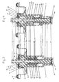
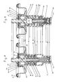
- valve for the metered delivery of liquids is inserted into a valve plate 10 which is attached via an outer seal 12 to a fluid container, not shown.
- the valve disk 10 has a base 13 which merges toward the center into a cylindrical portion 14 facing away from the fluid container and pointing upwards.
- a valve housing 20 is inserted, which extends down into the fluid container.
- a plurality of spaced indentations 15 are arranged, which engage behind a circumferential outer step 25 of the valve housing 20, whereby a depression of the valve is prevented in the fluid container.
- the valve is held in place by a lid portion 16, which is a horizontally extending continuation of the cylindrical portion 14 and has an opening 11.
- the opening 11 in the lid portion 16 forms the opening of the fluid container.
- the valve housing 20 is substantially cylindrical and, in addition to an upper inner stage 24 belonging to the outer step 25 in the upper region, has two further stepped tapers. These are in a lower region of the valve housing 20, a central inner stage 26 and a lower inner lower step 27. At the lower inner stage 27, at a lower, facing the interior of the fluid container end of the valve housing 20, an input port 21 is defined. At the top, ie at the container end, the valve body is closed by an insert 22 which rests on the upper inner stage 24. The Insert 22 and the upper seal 23 arranged thereon are clamped between the upper inner stage 24 and the lid portion 16 of the valve disk 10. The insert 22 and the upper seal 23 have an opening 11 of the valve disc 10 corresponding opening, wherein the diameter of the opening of the insert 22 is slightly larger than that of the upper seal 23rd
- a shaft body 40, a valve piston 30 and an inlet valve 50 hereinafter referred to as plug 50, arranged.
- the plug 50 and a lower seal 51 arranged underneath are guided in the valve housing 20 above the lower inner stage 27 and are at this stage on actuation of the valve.
- the plug 50 is raised.
- the plug and the seal have a diameter which is smaller than the inner diameter of the valve housing 20 in this area.
- the diameter of the plug 50 and the lower seal 51 are selected so that the plug 50 sealingly abuts the lower inner stage 27 upon actuation of the valve and the inlet opening 21 closes.
- channel-like recesses may also be provided on the inner circumference of the valve housing 20 or on the circumference of the plug 50 and the lower seal 51 for this purpose.
- the valve piston 30 has on its circumference a circumferential piston sealing lip 34 which bears sealingly against the inner wall of the valve housing 20. Between the valve piston 30 and the plug 50, a lower spring 9 is arranged, the valve piston 30 and plug 50 biases against each other. In the embodiment according to FIGS. 1-4 the plug 50 serves to guide the lower spring 9 and extends into the valve housing 20 accordingly. In this area, between valve piston 30 and plug 50, a first partial volume 3 is defined. Through the valve piston 30 extends in the axial direction, a piston channel 31. Above the Piston sealing lip 34, the valve piston 30 has an upper portion 32 with a smaller diameter, whereby a step 36 is formed.
- the shaft body 40 of the valve according to FIGS. 1-4 has a lower portion 49 of smaller diameter, which extends into the piston channel 31 of the valve piston 30 and sealingly guided therein.
- the piston channel 31 has a circumferential reduction in the inner diameter 38, which cooperates with a circumferential thickening 491 of the lower portion 49 of the shaft body 40 and limited by the upper spring 8 axial displacement of the valve piston 30 and the shaft body 40 against each other.
- an axial input channel 42 extends, which opens into two lower transverse channels 43, which lead slightly above the step 411 of the shaft 41 from this.
- the stage 411 of the shaft body 40 bears against the insert part 22 of the valve housing 20. In this position, the outputs of the lower transverse channels 43 are at the level of the insert 22, below the upper Seal 23.
- the piston channel 31, the input channel 42 and the lower transverse channels 43 define a second sub-volume second
- the shaft body 40 has a bottom-open, cylindrical cavity 46, which extends approximately to the level of the shaft sealing lip 48.
- the upper portion 32 of the valve piston 30 extends into this cylindrical cavity 46 and is sealingly guided therein.
- the upper portion 32 of the valve piston 30 has at its upper end a circumferential thickening 33, which cooperates with a circumferential, pointing into the cylindrical cavity 46 projection 47 at the lower end of the shaft body 40.
- the cylindrical cavity 46 continues upward in an axial input channel 42.
- Two lower transverse channels 43 lead from the input channel 42 to the outside.
- the stage 411 of the shaft body 40 bears against the insert part 22 of the valve housing 20.
- the outputs of the lower transverse channels 43 are at the level of the insert 22, below the upper seal 23.
- the cylindrical cavity 46, the input channel 42 and the lower transverse channels 43 define a second partial volume second
- an axial output channel 44 which opens into a container-shaped opening of the shaft 41.
- two upper transverse channels 45 are arranged, which from the output channel 44 to lead outside. In the closed state of the valve, the outputs of the upper transverse channels 45 are above the opening 11 of the valve disk 10th
- the plug 50 has vertical, channel-like recesses 53, approximately at the level of the central inner stage 26, which have a fluid connection between the first partial volume 3 and the second partial volume 2 when the valve piston 30 is pushed over the plug 30 to the middle inner stage.
- valve can also be described as a pumping device.
- pressures are also created when the valve is actuated, which gives the arrangement the function of a manual pump.
- FIG. 9 shows an alternative embodiment of a shaft body 40 in the FIGS. 5 to 8 shown embodiment of the valve according to the invention.
- Input channel 42 and output channel 44 are in this case arranged at an angle to the longitudinal axis of the shaft body, so that can be dispensed with transverse channels 43, 45.
Landscapes
- Chemical & Material Sciences (AREA)
- Dispersion Chemistry (AREA)
- Engineering & Computer Science (AREA)
- Mechanical Engineering (AREA)
- Containers And Packaging Bodies Having A Special Means To Remove Contents (AREA)
Applications Claiming Priority (1)
| Application Number | Priority Date | Filing Date | Title |
|---|---|---|---|
| DE102009022215A DE102009022215B4 (de) | 2009-05-20 | 2009-05-20 | Ventil zur dosierten Abgabe von Flüssigkeiten |
Publications (2)
| Publication Number | Publication Date |
|---|---|
| EP2253560A2 true EP2253560A2 (fr) | 2010-11-24 |
| EP2253560A3 EP2253560A3 (fr) | 2011-08-31 |
Family
ID=42288667
Family Applications (1)
| Application Number | Title | Priority Date | Filing Date |
|---|---|---|---|
| EP10005003A Withdrawn EP2253560A3 (fr) | 2009-05-20 | 2010-05-12 | Soupape de dépôt dosé de liquides |
Country Status (2)
| Country | Link |
|---|---|
| EP (1) | EP2253560A3 (fr) |
| DE (1) | DE102009022215B4 (fr) |
Cited By (3)
| Publication number | Priority date | Publication date | Assignee | Title |
|---|---|---|---|---|
| US9254954B2 (en) | 2010-08-18 | 2016-02-09 | Summit Packaging Systems, Inc. | Metering valve |
| EP3536634A1 (fr) * | 2018-03-09 | 2019-09-11 | Aptar Radolfzell GmbH | Distributeur destiné à la distribution de liquides et procédé de fonctionnement correspondant |
| RU2776433C2 (ru) * | 2018-03-09 | 2022-07-20 | Аптар Радольфцелль Гмбх | Диспенсер для выдачи жидкостей и способ его функционирования |
Family Cites Families (11)
| Publication number | Priority date | Publication date | Assignee | Title |
|---|---|---|---|---|
| FR1461685A (fr) * | 1965-10-29 | 1966-02-25 | Idees | Perfectionnement aux valves doseuses fonctionnant sous l'action d'un gaz comprimé |
| US3583605A (en) * | 1969-01-17 | 1971-06-08 | Diamond Int Corp | Liquid dispensing pump |
| FR2300950A1 (fr) * | 1975-02-12 | 1976-09-10 | Valois Sa | Valve doseuse du type aerosol |
| FR2615172B1 (fr) * | 1987-05-11 | 1989-08-18 | Valois | Valve aerosol doseuse utilisable en position inversee |
| FR2752411B1 (fr) * | 1996-08-14 | 1998-10-30 | Valois | Organe de fixation d'un dispositif de distribution sur un col d'un reservoir |
| GB9626960D0 (en) * | 1996-12-27 | 1997-02-12 | Glaxo Group Ltd | Valve for aerosol container |
| FR2776633B1 (fr) * | 1998-03-26 | 2000-06-09 | Valois Sa | Dispositif de distribution airless |
| DE10220557A1 (de) * | 2002-05-02 | 2003-11-13 | Pfeiffer Erich Gmbh & Co Kg | Spender zum Austrag fließfähiger Medien |
| US20060124903A1 (en) * | 2003-06-10 | 2006-06-15 | Astellas Pharma Inc. | Aerosol preparation comprising sealed container and enclosed therein aerosol composition containing marcolide compound |
| DE102004034626A1 (de) * | 2004-06-17 | 2006-01-12 | Seaquist Perfect Dispensing Gmbh | Dosierventil und Vorrichtung zur Abgabe einer vorzugsweise kosmetischen Flüssigkeit |
| ITMI20061266A1 (it) * | 2006-06-29 | 2007-12-30 | Microspray Delta Spa | Pompa semplificata di mandata di sostanze fluide prelevate da un contenitore |
-
2009
- 2009-05-20 DE DE102009022215A patent/DE102009022215B4/de not_active Expired - Fee Related
-
2010
- 2010-05-12 EP EP10005003A patent/EP2253560A3/fr not_active Withdrawn
Non-Patent Citations (1)
| Title |
|---|
| None |
Cited By (4)
| Publication number | Priority date | Publication date | Assignee | Title |
|---|---|---|---|---|
| US9254954B2 (en) | 2010-08-18 | 2016-02-09 | Summit Packaging Systems, Inc. | Metering valve |
| EP3536634A1 (fr) * | 2018-03-09 | 2019-09-11 | Aptar Radolfzell GmbH | Distributeur destiné à la distribution de liquides et procédé de fonctionnement correspondant |
| US10661291B2 (en) | 2018-03-09 | 2020-05-26 | Aptar Radolfzell Gmbh | Dispenser for discharging liquids, and operating method therefor |
| RU2776433C2 (ru) * | 2018-03-09 | 2022-07-20 | Аптар Радольфцелль Гмбх | Диспенсер для выдачи жидкостей и способ его функционирования |
Also Published As
| Publication number | Publication date |
|---|---|
| EP2253560A3 (fr) | 2011-08-31 |
| DE102009022215A1 (de) | 2010-11-25 |
| DE102009022215B4 (de) | 2011-06-22 |
Similar Documents
| Publication | Publication Date | Title |
|---|---|---|
| EP2605858B1 (fr) | Module de distribution et procédé pour remplir un module de distribution | |
| EP2605857B1 (fr) | Module de distribution | |
| EP1373094B1 (fr) | Recipient sous pression permettant de melanger et de distribuer des materiaux a deux composants | |
| DE1400733A1 (de) | Dosierdruckkappe | |
| EP3536634B1 (fr) | Distributeur destiné à la distribution de liquides et procédé de fonctionnement correspondant | |
| EP0152761B1 (fr) | Dispositif pour la fabrication et la vaporisation d'un mélange constitué d'au moins deux composants, p.e. liquides, et d'un gaz sous pression | |
| EP1578676B1 (fr) | Capsule sous pression pour melanger et produire des materiaux a deux composantes | |
| EP1199106B1 (fr) | Distributeur-doseur de produit fluide avec une pompe à main intégrée dans le récipient | |
| DE1027945B (de) | Abgabeventil | |
| DE2605474A1 (de) | Dosierventil fuer aerosole | |
| DE3405064A1 (de) | Vorrichtung zum herstellen und verspruehen einer aus wenigstens zwei komponenten, z. b. fluessigkeiten, und einem treibgas bestehenden mischung | |
| DE102009022215B4 (de) | Ventil zur dosierten Abgabe von Flüssigkeiten | |
| DE2017878A1 (de) | Ventil zur Zerstäubung von flüssigen Erzeugnissen unter Druck | |
| EP1124738A1 (fr) | Valve pour la distribution de fluides sous pression | |
| AT388715B (de) | Dosierventil | |
| EP2393730B1 (fr) | Distributeur pour la distribution dosée d'une formulation de gaz liquéfié et procédé pour la fabrication du distributeur | |
| EP2141087A2 (fr) | Récipient de sortie pouvant être rempli de nouveau pour liquides | |
| EP0131204B1 (fr) | Dispositif pour mélanger et distribuer un mélange composé par au moins deux composantes, par exemple des liquides et un gaz propulseur | |
| DE3236552A1 (de) | Pump-dosierverschluss | |
| DE1939259C (de) | Ventil fur Aerosolbehälter | |
| DE1939259B2 (de) | Ventil fuer aerosolbehaelter | |
| WO2007087737A1 (fr) | procede de remplissage de l'espace interieur d'une conserve par un fluide sous pression | |
| DE8227683U1 (de) | Pump-Dosierverschluß | |
| DE1930088B2 (de) | Mischungsabgabegeraet |
Legal Events
| Date | Code | Title | Description |
|---|---|---|---|
| PUAI | Public reference made under article 153(3) epc to a published international application that has entered the european phase |
Free format text: ORIGINAL CODE: 0009012 |
|
| AK | Designated contracting states |
Kind code of ref document: A2 Designated state(s): AL AT BE BG CH CY CZ DE DK EE ES FI FR GB GR HR HU IE IS IT LI LT LU LV MC MK MT NL NO PL PT RO SE SI SK SM TR |
|
| AX | Request for extension of the european patent |
Extension state: BA ME RS |
|
| PUAL | Search report despatched |
Free format text: ORIGINAL CODE: 0009013 |
|
| AK | Designated contracting states |
Kind code of ref document: A3 Designated state(s): AL AT BE BG CH CY CZ DE DK EE ES FI FR GB GR HR HU IE IS IT LI LT LU LV MC MK MT NL NO PL PT RO SE SI SK SM TR |
|
| AX | Request for extension of the european patent |
Extension state: BA ME RS |
|
| RIC1 | Information provided on ipc code assigned before grant |
Ipc: B65D 83/14 20060101AFI20110725BHEP |
|
| 17P | Request for examination filed |
Effective date: 20120208 |
|
| RIC1 | Information provided on ipc code assigned before grant |
Ipc: B65D 83/54 20060101AFI20140509BHEP |
|
| GRAP | Despatch of communication of intention to grant a patent |
Free format text: ORIGINAL CODE: EPIDOSNIGR1 |
|
| INTG | Intention to grant announced |
Effective date: 20150116 |
|
| STAA | Information on the status of an ep patent application or granted ep patent |
Free format text: STATUS: THE APPLICATION IS DEEMED TO BE WITHDRAWN |
|
| 18D | Application deemed to be withdrawn |
Effective date: 20150527 |