EP2253875A2 - Bride pour joint de tuyaux - Google Patents
Bride pour joint de tuyaux Download PDFInfo
- Publication number
- EP2253875A2 EP2253875A2 EP09710112A EP09710112A EP2253875A2 EP 2253875 A2 EP2253875 A2 EP 2253875A2 EP 09710112 A EP09710112 A EP 09710112A EP 09710112 A EP09710112 A EP 09710112A EP 2253875 A2 EP2253875 A2 EP 2253875A2
- Authority
- EP
- European Patent Office
- Prior art keywords
- band
- hose
- coupling unit
- clamping member
- clamping
- Prior art date
- Legal status (The legal status is an assumption and is not a legal conclusion. Google has not performed a legal analysis and makes no representation as to the accuracy of the status listed.)
- Withdrawn
Links
- 230000008878 coupling Effects 0.000 claims description 40
- 238000010168 coupling process Methods 0.000 claims description 40
- 238000005859 coupling reaction Methods 0.000 claims description 40
- 238000003780 insertion Methods 0.000 claims description 9
- 230000037431 insertion Effects 0.000 claims description 9
- 238000004519 manufacturing process Methods 0.000 description 4
- 239000000463 material Substances 0.000 description 3
- 238000010276 construction Methods 0.000 description 2
- 238000012423 maintenance Methods 0.000 description 2
- 238000000034 method Methods 0.000 description 2
- 238000007669 thermal treatment Methods 0.000 description 2
- 229910000831 Steel Inorganic materials 0.000 description 1
- 239000004809 Teflon Substances 0.000 description 1
- 229920006362 Teflon® Polymers 0.000 description 1
- 238000007792 addition Methods 0.000 description 1
- 229910052782 aluminium Inorganic materials 0.000 description 1
- XAGFODPZIPBFFR-UHFFFAOYSA-N aluminium Chemical compound [Al] XAGFODPZIPBFFR-UHFFFAOYSA-N 0.000 description 1
- 230000000694 effects Effects 0.000 description 1
- 239000013013 elastic material Substances 0.000 description 1
- 238000009434 installation Methods 0.000 description 1
- 239000007769 metal material Substances 0.000 description 1
- 238000012986 modification Methods 0.000 description 1
- 230000004048 modification Effects 0.000 description 1
- 229920001296 polysiloxane Polymers 0.000 description 1
- 229920000915 polyvinyl chloride Polymers 0.000 description 1
- 230000000717 retained effect Effects 0.000 description 1
- 239000010959 steel Substances 0.000 description 1
- 238000006467 substitution reaction Methods 0.000 description 1
Images





Classifications
-
- F—MECHANICAL ENGINEERING; LIGHTING; HEATING; WEAPONS; BLASTING
- F16—ENGINEERING ELEMENTS AND UNITS; GENERAL MEASURES FOR PRODUCING AND MAINTAINING EFFECTIVE FUNCTIONING OF MACHINES OR INSTALLATIONS; THERMAL INSULATION IN GENERAL
- F16L—PIPES; JOINTS OR FITTINGS FOR PIPES; SUPPORTS FOR PIPES, CABLES OR PROTECTIVE TUBING; MEANS FOR THERMAL INSULATION IN GENERAL
- F16L33/00—Arrangements for connecting hoses to rigid members; Rigid hose-connectors, i.e. single members engaging both hoses
- F16L33/02—Hose-clips
- F16L33/08—Hose-clips in which a worm coacts with a part of the hose-encircling member that is toothed like a worm-wheel
-
- F—MECHANICAL ENGINEERING; LIGHTING; HEATING; WEAPONS; BLASTING
- F16—ENGINEERING ELEMENTS AND UNITS; GENERAL MEASURES FOR PRODUCING AND MAINTAINING EFFECTIVE FUNCTIONING OF MACHINES OR INSTALLATIONS; THERMAL INSULATION IN GENERAL
- F16L—PIPES; JOINTS OR FITTINGS FOR PIPES; SUPPORTS FOR PIPES, CABLES OR PROTECTIVE TUBING; MEANS FOR THERMAL INSULATION IN GENERAL
- F16L33/00—Arrangements for connecting hoses to rigid members; Rigid hose-connectors, i.e. single members engaging both hoses
- F16L33/02—Hose-clips
-
- F—MECHANICAL ENGINEERING; LIGHTING; HEATING; WEAPONS; BLASTING
- F16—ENGINEERING ELEMENTS AND UNITS; GENERAL MEASURES FOR PRODUCING AND MAINTAINING EFFECTIVE FUNCTIONING OF MACHINES OR INSTALLATIONS; THERMAL INSULATION IN GENERAL
- F16L—PIPES; JOINTS OR FITTINGS FOR PIPES; SUPPORTS FOR PIPES, CABLES OR PROTECTIVE TUBING; MEANS FOR THERMAL INSULATION IN GENERAL
- F16L21/00—Joints with sleeve or socket
- F16L21/06—Joints with sleeve or socket with a divided sleeve or ring clamping around the pipe ends
-
- Y—GENERAL TAGGING OF NEW TECHNOLOGICAL DEVELOPMENTS; GENERAL TAGGING OF CROSS-SECTIONAL TECHNOLOGIES SPANNING OVER SEVERAL SECTIONS OF THE IPC; TECHNICAL SUBJECTS COVERED BY FORMER USPC CROSS-REFERENCE ART COLLECTIONS [XRACs] AND DIGESTS
- Y10—TECHNICAL SUBJECTS COVERED BY FORMER USPC
- Y10T—TECHNICAL SUBJECTS COVERED BY FORMER US CLASSIFICATION
- Y10T24/00—Buckles, buttons, clasps, etc.
- Y10T24/14—Bale and package ties, hose clamps
- Y10T24/1412—Bale and package ties, hose clamps with tighteners
- Y10T24/1439—Radial screw
Definitions
- the present invention relates, in general, to a hose fastening clamp which is used to hold hoses that are connected by various pipe connectors in such a way as to be butted to each other, in addition to maintaining airtightness and, more particularly, to a hose fastening clamp, which prevents an outer covering of a hose that is in contact with a band from being pushed in the rotating direction of the band, and increases a clamping force using the band fastened to the hose.
- Hoses which have been used in a variety of fields are manufactured to have various shapes with various materials according to the quality of the material, the thermal treatment method, the purpose of use, and the place of installation. Since the hoses are inexpensive and convenient to install, the use of hoses is gradually increasing.
- the hose is bent or curved according to the place where it is to be installed, and is butted to an adjacent hose.
- a fastening clamp is provided on a joint of neighboring hoses so as to prevent objects flowing into the hoses from leaking out and to increase a coupling force between the neighboring hoses.
- a conventional fastening clamp includes a clamping band unit having threads which are formed on a surface thereof at regular intervals, and a fastening screw unit which is rotated to adjust the length of the clamping band unit.
- the fastening screw unit rotates, the length of the clamping band unit is adjusted, so that the joint of the hoses is compressed.
- the conventional fastening clamp 100 includes a clamping band unit 110 and a fastening screw unit 120.
- the clamping band unit 110 has the shape of a plate, with threads 111 formed on a surface thereof at regular intervals.
- the fastening screw unit 120 engages with the threads 111 which are formed on the clamping band unit 110 in a threaded manner, and is provided with a screwhead 122 to rotate the fastening screw unit.
- the fastening screw unit 120 rotates, thus moving the threads 111 forwards or backwards. Thereby, the clamping band unit 110 compresses the hose S.
- Such a conventional fastening clamp has no problem when objects in the hose flow at a lower speed and under a lower pressure.
- the fastening clamp is problematic in that it may be easily loosened by the expansion of the hose when the flow rate and pressure of the objects are high.
- the fastening clamp compressing the joint between neighboring hoses is loosened, thus frequently resulting in the leakage of objects from the hoses.
- the clamping band unit is fastened while being advanced by the fastening screw unit which rotates around a position at which the clamping band unit is inserted into the fastening screw unit.
- the thickness of the outer covering changes considerably.
- the outer covering of the hose is thickest. Since the position "3" is distant from the inserted position "11" in the inserting direction, the outer covering of the hose is formed to be thin. Meanwhile, since the position "9" is near the inserted position "11" in the inserting direction, the outer covering of the hose at the position "9" is thicker than that at the position "3".
- the thickness of the outer covering is reduced. The nearer the distance is, the thicker the outer covering is.
- Such a conventional fastening clamp is problematic in that it is impossible to perform a clamping operation in the state where the thickness of the outer covering of the hose is kept constant, so that a clamping force is gradually reduced because the outer covering of the hose is restored to its original state when a lengthy period of time has passed after the fastening operation was performed, and thus the fastening clamp may become dismantled. Moreover, if the clamping operation is forcibly performed with an excessively large force, the outer covering of the hose may be damaged.
- connection band includes a body having a pair of plates. Bent parts are provided on both sides of the body. A locking pin having a hole and a locking pin having a screw hole are inserted into the corresponding bent parts, so that a bolt is inserted into the hole to be fastened to an associated screw hole. Further, an auxiliary clamping pipe is mounted to the inner surface of the body, and is compressed by the body which is controlled by tightening the bolt, thus clamping the circumference of a hose.
- the prior art 1 is problematic in that it is complicated to mount the auxiliary clamping pipe to the inner surface of the body, skilled workers must find a precise mounting position so as to increase a clamping force generated when the auxiliary clamping pipe clamps the circumference of the hose by the compressing force transmitted from the body, and such an operation is not easy. Further, when the circumference of the hose is made of an elastic material, it expands outwards and thus pushes the auxiliary clamping pipe, and the auxiliary clamping pipe pushed to a predetermined position moves upwards or downwards to be removed from the body of the band.
- an object of the present invention is to provide a hose fastening clamp, which compresses the outer covering of a hose, thus increasing a clamping force, preventing the outer covering from being damaged when the hose is clamped, and retaining a clamping force even when a lengthy period of time has passed after the hose was clamped.
- Another object of the present invention is to provide a hose fastening clamp, which is capable of preventing the outer covering of a hose from being pushed in a band fastening direction.
- a further object of the present invention is to provide a hose fastening clamp, which may be easily coupled to a hose, thus allowing general consumers as well as skilled workers to easily use the hose fastening clamp, therefore affording improved convenience.
- Yet another object of the present invention is to provide a hose fastening clamp, which has a simple construction and enables the ease of manufacture, so that manufacturing costs are reduced, an additional maintenance cost incurred by a hose fastening operation is reduced, and thus the hose fastening clamp is economical.
- the present invention provides a hose fastening clamp including a band which has on an outer surface thereof a thread and forms an open ring that surrounds a hose, a fastening screw which engages with the thread to adjust a diameter of the open ring, and a clamping member which is placed to be in contact with an inner surface of the band, a diameter of the clamping member being changed in conjunction with a change in diameter of the open ring.
- the clamping member may include a body, and a coupling unit which protrudes outwards from a predetermined portion of the body and is coupled to the band.
- the coupling unit may comprise a first coupling unit, the first coupling unit including an insertion hole into which the band is inserted, and a locking part which is bent to an outer surface of the inserted band and is thus locked.
- the coupling unit may comprise a second coupling unit, the second coupling unit including a slotted part which has a slot having a predetermined length and receiving each of right and left edges of the band.
- the coupling unit may be formed on either or both of opposite ends of the clamping member.
- a hose fastening clamp is advantageous in that a high clamping force can be obtained without damaging an outer covering of a hose when neighboring hoses are connected to each other, and a clamping force is continuously retained even when a lengthy period of time has passed after the fastening operation was performed so that watertightness and airtightness are maintained, thus reducing maintenance costs, and objects flowing in the hose are not exposed to the outside, thus preventing an unexpected accident.
- a hose fastening clamp is advantageous in that it has a simple construction, so that skilled workers or common consumers may easily use the hose fastening clamp.
- a hose fastening clamp is advantageous in that it is convenient to manufacture, so that manufacturing costs can be reduced and thus the hose fastening clamp is economical.
- a threaded side formed on the band is designated as an outer side or an outer surface
- an open ring side formed by the band is designated as an inner side or inner surface
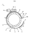
- the hose fastening clamp 1 includes a band 10, a fastening screw 20, and a clamping member 30.
- the band 10 has on its outer surface 12 threads 13, and forms an open ring C which surrounds a hose S.
- the fastening screw 20 is provided at a predetermined position on the band 10, has on its inner surface corresponding threads 21 which are in contact with the threads 13, with a screwhead 22 provided on the fastening screw 20 to rotate it.
- the clamping member 30 is placed to be in contact with the inner surface 11 of the band 10, and the diameter of the clamping member is changed in conjunction with a change in diameter of the open ring C which is adjusted by rotating the fastening screw 20.
- the band 10 may have various strengths according to the material, thermal treatment method, and interval between the threads 13, and may be made of Teflon, PVC, silicone, steel, and a metal material such as aluminum.
- the threads 13 are formed on the outer surface 12 of the band 10 at regular intervals, and engage with the corresponding threads 21 formed on the fastening screw 20 in a threaded manner, so that the threads 13 move forwards or backwards by rotating the fastening screw 20, and thus the diameter of the open ring C defined by the band 10 is adjusted.
- the fastening screw 20 into which the band 10 is inserted has on its inner surface the threads 21 which correspond to the threads 13 formed on the band 10, and includes the screwhead 22 to rotate the threads.
- the fastening screw is integrally secured to a predetermined position on the band 10.
- a cross-shaped or hexagonal groove is formed in the screwhead 22 of the fastening screw 20, so that the fastening screw 20 is rotated using a Phillips screwdriver or a hexagonal wrench to be easily tightened or loosened.
- the diameter of the open ring C defined by the band 10 over which the fastening screw is fitted is adjusted to be small, so that the inner surface 11 of the band 10 is in close contact with the hose S.
- the diameter of the open ring C is increased, so that the band is released from the hose S.
- the clamping member 30 which is placed to be in contact with the inner surface 11 of the band 10 will be described with reference to FIGS. 4 to 7 .
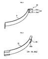
- the clamping member includes a body 31 and a coupling unit 32 which is provided to protrude outwards from a predetermined position on the body 31.
- the body 31 has the shape of a plate of a predetermined length, and is in close contact with or released from the outer covering Sa of the hose S in conjunction with a change in diameter of the open ring C defined by the band 10.
- the coupling unit 32 provided at a predetermined position on the body 31 is locked to the band 10, thus holding the body 31 at a predetermined position.
- the coupling unit 32 may comprise a first coupling unit 33 including an insertion hole 33a into which the band 10 is inserted, and a locking part 33b which is bent outwards relative to the inserted band 10 to be locked.
- the first coupling unit 33 may be formed on either or both of the opposite ends or a predetermined position of the body 31.
- the coupling unit 32 may comprise a second coupling unit 34 including a slotted part 35.
- the slotted part has slots 35a of a predetermined length to receive the right and left edges 15 of the band 10.
- the slotted part 35 is compressed towards the band 10, so that the slotted part 35 is secured to the right and left edges 15 of the band 10.
- the first or second coupling unit 33 or 34 may be provided on either or both of the opposite ends or a predetermined position of the body 31. Both the first and coupling units 33 and 34 may be used together.
- each of the first and second coupling units 33 and 34 protrudes outwards from the body 31, and has the insertion hole 33a or the slots 35a into which the band 10 is inserted. If necessary, a plurality of first or second coupling units may be provided at predetermined positions on the body 31.
- the sequence in which the clamping member 30 having on the opposite ends of the body 31 the first coupling units 33 is coupled to the band 10 will be described.
- the first coupling unit 33 provided on the other end is located at a position corresponding to the end 14 of the band 10 so that the band 10 surrounding the hose S is inserted into the first coupling unit.
- the end 14 is inserted into the insertion hole 33a of the first coupling unit 33 which is provided on the other end of the clamping member, and the band 10 firmly holds the hose S.
- the locking parts 33b of the first coupling units 33 provided on the opposite ends of the clamping member are bent to be in close contact with the outer covering Sa of the band 10 and are locked.
- the clamping member 30 may be rotated to a desired position while it is coupled to the band 10.
- the clamping member compresses the overlapping portion Sp of the outer covering Sa of the hose S during the fastening operation, thus preventing the outer covering Sa from being damaged.
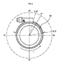
- the outer covering Sa of the hose S has different thicknesses depending on the clamping direction J of the band 10 which is in close contact with the hose.
- the outer covering Sa is pushed towards the fastening screw 20, so that it becomes thinner.
- the outer covering Sa maintains a constant thickness without change. Consequently, a portion of the outer covering Sa pushed from the distant positions "9” to “6” overlaps a portion of the outer covering which is placed at the near positions "1" to "3".
- the clamping member 30 is rotated to be located at the overlapping portion Sp of the outer covering Sa.
- the clamping member 30 compresses the outer covering Sa to press the overlapping portion Sp of the outer covering Sa, so that the outer covering Sa is restored to its original state. Further, a portion of the outer covering Sa located at the distant positions "9" to "6" is compressed, thus preventing the outer covering Sa from being moved in the clamping direction J.
- the clamping member 30 has elasticity so that its diameter is changed in conjunction with a change in diameter of the open ring C defined by the band 10 and thus the clamping member is in close contact with the outer covering Sa of the hose S.
- the end 14 of the band 10 is inserted into the insertion hole 33a of the first coupling unit 33 which is provided on one end of the clamping member 30 so that the clamping member 30 is placed on the inner surface of the band 10.
- the clamping member 30 coupled to the band in this way is rotated to be located at a predetermined position on the inner surface 11 of the band 10.
- the band 10 is placed on the outer covering Sa of the hose S such that the band 10 surrounds the hose S.
- the end 14 of the band 10 is inserted into the insertion hole 33a of the first coupling unit 33 which is formed on the other end of the clamping member 30, and thereafter is inserted into the fastening screw 20.
- the band is inserted to a predetermined length such that the threads 13 provided on the outer surface 12 of the band 10 engage with the corresponding threads 21 provided in the fastening screw 20.
- the screwhead 22 of the fastening screw 20 is rotated in the coupling direction to reduce the diameter of the open ring C defined by the band 10, so that the inner surface 11 of the band 10 is in close contact with the outer covering Sa of the hose S, and thus the hose is clamped.
- the clamping member 30 placed on the inner surface 11 of the band 10 comes into close contact with the outer covering Sa of the hose S, thus preventing the outer covering Sa of the hose S from being pushed in the moving direction of the band 10.
- the clamping member 30 is rotated to be located at the overlapping portion of the outer covering Sa before the clamping member 30 is secured to the band 10. In this state, if the clamping member 30 is secured to the band 10, the overlapping portion of the outer covering Sa is restored to its original state by the compressing force of the clamping member 30.
Landscapes
- Engineering & Computer Science (AREA)
- General Engineering & Computer Science (AREA)
- Mechanical Engineering (AREA)
- Clamps And Clips (AREA)
- Supports For Pipes And Cables (AREA)
Applications Claiming Priority (2)
| Application Number | Priority Date | Filing Date | Title |
|---|---|---|---|
| KR1020080014178A KR100867746B1 (ko) | 2008-02-15 | 2008-02-15 | 호스체결용 클램프 |
| PCT/KR2009/000624 WO2009102137A2 (fr) | 2008-02-15 | 2009-02-11 | Bride pour joint de tuyaux |
Publications (1)
| Publication Number | Publication Date |
|---|---|
| EP2253875A2 true EP2253875A2 (fr) | 2010-11-24 |
Family
ID=40283903
Family Applications (1)
| Application Number | Title | Priority Date | Filing Date |
|---|---|---|---|
| EP09710112A Withdrawn EP2253875A2 (fr) | 2008-02-15 | 2009-02-11 | Bride pour joint de tuyaux |
Country Status (5)
| Country | Link |
|---|---|
| US (1) | US20100306968A1 (fr) |
| EP (1) | EP2253875A2 (fr) |
| KR (1) | KR100867746B1 (fr) |
| CN (1) | CN102007335A (fr) |
| WO (1) | WO2009102137A2 (fr) |
Cited By (2)
| Publication number | Priority date | Publication date | Assignee | Title |
|---|---|---|---|---|
| EP2541117A1 (fr) * | 2011-06-29 | 2013-01-02 | Dong-A Metal Co., Ltd. | Collier de serrage pour tuyau |
| WO2017137197A1 (fr) * | 2016-02-09 | 2017-08-17 | Norma Germany Gmbh | Collier de serrage |
Families Citing this family (6)
| Publication number | Priority date | Publication date | Assignee | Title |
|---|---|---|---|---|
| US10179401B2 (en) * | 2016-09-02 | 2019-01-15 | Thomas John Nyland | Pivotal arm support device |
| KR102108639B1 (ko) * | 2018-10-10 | 2020-05-07 | 김미예 | 원웨이 락킹구조를 갖는 소방호스 리프팅용 걸이구 |
| CN109253333B (zh) * | 2018-11-20 | 2023-08-15 | 佛山科学技术学院 | 一种不锈钢管连接组件 |
| CN110356712B (zh) * | 2019-07-25 | 2021-01-29 | 徐州易尚饰家装饰工程有限责任公司 | 一种回转轴承转运支托防护环 |
| CN113483172B (zh) * | 2021-07-02 | 2022-02-18 | 泰州市华驰不锈钢制品有限公司 | 一种防松的快卸式卡箍 |
| CN114775589A (zh) * | 2022-03-29 | 2022-07-22 | 中建东设岩土工程有限公司 | 一种对预制桩接头处防腐的保护方法 |
Family Cites Families (13)
| Publication number | Priority date | Publication date | Assignee | Title |
|---|---|---|---|---|
| US3389442A (en) * | 1966-05-13 | 1968-06-25 | Wittek Mfg Co | Hose clamp with load distributing member |
| US3477106A (en) * | 1968-03-22 | 1969-11-11 | Wittek Mfg Co | Hose clamp with hose attaching means |
| DE4005631A1 (de) * | 1990-02-22 | 1991-09-05 | Rasmussen Gmbh | Schlauchschelle |
| JPH0726712B2 (ja) * | 1991-08-16 | 1995-03-29 | ラスムッセン ジイエムビイエイチ | ホースクリップ |
| KR970010255U (ko) * | 1995-08-22 | 1997-03-29 | 호스연결용 클램프구조 | |
| US5742984A (en) * | 1996-10-07 | 1998-04-28 | Ford Global Technologies, Inc. | Strap tensioning apparatus |
| FR2758604B1 (fr) * | 1997-01-21 | 1999-04-02 | Lionel Calmettes | Collier de serrage |
| KR200187887Y1 (ko) | 2000-02-03 | 2000-07-15 | 고문주 | 호스 연결밴드 |
| KR100422527B1 (ko) * | 2000-12-28 | 2004-03-11 | 기아자동차주식회사 | 호스체결 클램프 구조 |
| JP4291305B2 (ja) * | 2005-07-20 | 2009-07-08 | 株式会社協栄ファスナー工業 | ホースクランプの弾力構造 |
| DE102006048336B4 (de) * | 2006-10-12 | 2013-07-04 | Norma Germany Gmbh | Schlauchschelle |
| DE102006048344B4 (de) * | 2006-10-12 | 2009-10-08 | Norma Germany Gmbh | Schlauchschelle |
| FR2919039B1 (fr) * | 2007-07-16 | 2012-12-28 | Caillau Ets | Dispositif de serrage avec collier de serrage et piece de positionnement |
-
2008
- 2008-02-15 KR KR1020080014178A patent/KR100867746B1/ko not_active Expired - Fee Related
-
2009
- 2009-02-11 WO PCT/KR2009/000624 patent/WO2009102137A2/fr not_active Ceased
- 2009-02-11 CN CN2009801129676A patent/CN102007335A/zh active Pending
- 2009-02-11 US US12/867,776 patent/US20100306968A1/en not_active Abandoned
- 2009-02-11 EP EP09710112A patent/EP2253875A2/fr not_active Withdrawn
Non-Patent Citations (1)
| Title |
|---|
| See references of WO2009102137A2 * |
Cited By (5)
| Publication number | Priority date | Publication date | Assignee | Title |
|---|---|---|---|---|
| EP2541117A1 (fr) * | 2011-06-29 | 2013-01-02 | Dong-A Metal Co., Ltd. | Collier de serrage pour tuyau |
| CN102853170A (zh) * | 2011-06-29 | 2013-01-02 | (株)东亚金属 | 软管夹 |
| CN102853170B (zh) * | 2011-06-29 | 2014-12-03 | (株)东亚金属 | 软管夹 |
| WO2017137197A1 (fr) * | 2016-02-09 | 2017-08-17 | Norma Germany Gmbh | Collier de serrage |
| US20190049048A1 (en) * | 2016-02-09 | 2019-02-14 | Gerrit Von Breitenbach | Hose Clamp |
Also Published As
| Publication number | Publication date |
|---|---|
| CN102007335A (zh) | 2011-04-06 |
| WO2009102137A2 (fr) | 2009-08-20 |
| US20100306968A1 (en) | 2010-12-09 |
| KR100867746B1 (ko) | 2008-11-10 |
| WO2009102137A3 (fr) | 2009-11-05 |
Similar Documents
| Publication | Publication Date | Title |
|---|---|---|
| EP2253875A2 (fr) | Bride pour joint de tuyaux | |
| EP2241766B1 (fr) | Collier de serrage | |
| US7179010B2 (en) | Adjustable pipe clamp assembly | |
| CA2739785C (fr) | Appareil a bride universel pour accessoires de plomberie | |
| US12215809B2 (en) | Systems and methods for a clamp | |
| US11802637B2 (en) | Apparatus for fastening lines | |
| US11384866B2 (en) | Pipe clamp | |
| CA2566271A1 (fr) | Raccord mecanique deformable de tuyauterie | |
| US12486927B2 (en) | Press-fitting connection structure for pipeline and refrigeration device | |
| TWI267585B (en) | Position detecting switch fixture for cylinder | |
| US10767791B2 (en) | Clamp with bracket apertures | |
| US7793988B1 (en) | Connector for electrical wire-carrying conduits | |
| KR100728174B1 (ko) | 관체 클램프기구 | |
| KR20170025928A (ko) | 밴드 클램프 장치 | |
| US20020166214A1 (en) | Pipe clamp, in particular, pipe coupling | |
| US20250192453A1 (en) | Clamp for conductors | |
| CN218494440U (zh) | 抱箍装置 | |
| CN222164046U (zh) | 一种封堵装置 | |
| JP3183013B2 (ja) | 管固定具 | |
| CN220354744U (zh) | 一种角度可调整的弯头三通法兰适配器 | |
| US10994395B1 (en) | Loop-type band clamp installation tool | |
| KR200257532Y1 (ko) | 밴드 클램프 | |
| JP2025523272A (ja) | クランプ | |
| EP1462666A1 (fr) | Dispositif de fixation d'un objet à un profilé à section essentiellement en forme de C | |
| CN109944998A (zh) | 一种360度可旋式快插组件 |
Legal Events
| Date | Code | Title | Description |
|---|---|---|---|
| PUAI | Public reference made under article 153(3) epc to a published international application that has entered the european phase |
Free format text: ORIGINAL CODE: 0009012 |
|
| 17P | Request for examination filed |
Effective date: 20100915 |
|
| AK | Designated contracting states |
Kind code of ref document: A2 Designated state(s): AT BE BG CH CY CZ DE DK EE ES FI FR GB GR HR HU IE IS IT LI LT LU LV MC MK MT NL NO PL PT RO SE SI SK TR |
|
| AX | Request for extension of the european patent |
Extension state: AL BA RS |
|
| STAA | Information on the status of an ep patent application or granted ep patent |
Free format text: STATUS: THE APPLICATION HAS BEEN WITHDRAWN |
|
| 18W | Application withdrawn |
Effective date: 20110303 |