EP2253977A2 - Wasserfester Steckverbinder und wasserfeste Vorrichtung, die diesen Steckverbinder einsetzt - Google Patents
Wasserfester Steckverbinder und wasserfeste Vorrichtung, die diesen Steckverbinder einsetzt Download PDFInfo
- Publication number
- EP2253977A2 EP2253977A2 EP20100001857 EP10001857A EP2253977A2 EP 2253977 A2 EP2253977 A2 EP 2253977A2 EP 20100001857 EP20100001857 EP 20100001857 EP 10001857 A EP10001857 A EP 10001857A EP 2253977 A2 EP2253977 A2 EP 2253977A2
- Authority
- EP
- European Patent Office
- Prior art keywords
- connector
- target
- unlocking means
- housing body
- waterproof
- Prior art date
- Legal status (The legal status is an assumption and is not a legal conclusion. Google has not performed a legal analysis and makes no representation as to the accuracy of the status listed.)
- Granted
Links
Images


Classifications
-
- G—PHYSICS
- G02—OPTICS
- G02B—OPTICAL ELEMENTS, SYSTEMS OR APPARATUS
- G02B6/00—Light guides; Structural details of arrangements comprising light guides and other optical elements, e.g. couplings
- G02B6/24—Coupling light guides
- G02B6/36—Mechanical coupling means
- G02B6/38—Mechanical coupling means having fibre to fibre mating means
- G02B6/3807—Dismountable connectors, i.e. comprising plugs
- G02B6/3873—Connectors using guide surfaces for aligning ferrule ends, e.g. tubes, sleeves, V-grooves, rods, pins, balls
- G02B6/3874—Connectors using guide surfaces for aligning ferrule ends, e.g. tubes, sleeves, V-grooves, rods, pins, balls using tubes, sleeves to align ferrules
- G02B6/3878—Connectors using guide surfaces for aligning ferrule ends, e.g. tubes, sleeves, V-grooves, rods, pins, balls using tubes, sleeves to align ferrules comprising a plurality of ferrules, branching and break-out means
- G02B6/3879—Linking of individual connector plugs to an overconnector, e.g. using clamps, clips, common housings comprising several individual connector plugs
-
- G—PHYSICS
- G02—OPTICS
- G02B—OPTICAL ELEMENTS, SYSTEMS OR APPARATUS
- G02B6/00—Light guides; Structural details of arrangements comprising light guides and other optical elements, e.g. couplings
- G02B6/24—Coupling light guides
- G02B6/36—Mechanical coupling means
- G02B6/38—Mechanical coupling means having fibre to fibre mating means
- G02B6/3807—Dismountable connectors, i.e. comprising plugs
- G02B6/381—Dismountable connectors, i.e. comprising plugs of the ferrule type, e.g. fibre ends embedded in ferrules, connecting a pair of fibres
- G02B6/3816—Dismountable connectors, i.e. comprising plugs of the ferrule type, e.g. fibre ends embedded in ferrules, connecting a pair of fibres for use under water, high pressure connectors
-
- G—PHYSICS
- G02—OPTICS
- G02B—OPTICAL ELEMENTS, SYSTEMS OR APPARATUS
- G02B6/00—Light guides; Structural details of arrangements comprising light guides and other optical elements, e.g. couplings
- G02B6/24—Coupling light guides
- G02B6/36—Mechanical coupling means
- G02B6/38—Mechanical coupling means having fibre to fibre mating means
- G02B6/3807—Dismountable connectors, i.e. comprising plugs
- G02B6/381—Dismountable connectors, i.e. comprising plugs of the ferrule type, e.g. fibre ends embedded in ferrules, connecting a pair of fibres
- G02B6/3825—Dismountable connectors, i.e. comprising plugs of the ferrule type, e.g. fibre ends embedded in ferrules, connecting a pair of fibres with an intermediate part, e.g. adapter, receptacle, linking two plugs
-
- G—PHYSICS
- G02—OPTICS
- G02B—OPTICAL ELEMENTS, SYSTEMS OR APPARATUS
- G02B6/00—Light guides; Structural details of arrangements comprising light guides and other optical elements, e.g. couplings
- G02B6/24—Coupling light guides
- G02B6/36—Mechanical coupling means
- G02B6/38—Mechanical coupling means having fibre to fibre mating means
- G02B6/3807—Dismountable connectors, i.e. comprising plugs
- G02B6/389—Dismountable connectors, i.e. comprising plugs characterised by the method of fastening connecting plugs and sockets, e.g. screw- or nut-lock, snap-in, bayonet type
- G02B6/3891—Bayonet type
-
- G—PHYSICS
- G02—OPTICS
- G02B—OPTICAL ELEMENTS, SYSTEMS OR APPARATUS
- G02B6/00—Light guides; Structural details of arrangements comprising light guides and other optical elements, e.g. couplings
- G02B6/24—Coupling light guides
- G02B6/36—Mechanical coupling means
- G02B6/38—Mechanical coupling means having fibre to fibre mating means
- G02B6/3807—Dismountable connectors, i.e. comprising plugs
- G02B6/389—Dismountable connectors, i.e. comprising plugs characterised by the method of fastening connecting plugs and sockets, e.g. screw- or nut-lock, snap-in, bayonet type
- G02B6/3893—Push-pull type, e.g. snap-in, push-on
Definitions
- the present invention relates to a waterproof connector, and a waterproof device using the waterproof connector.
- FIGS. 21 and 22 are perspective views showing a waterproof device disclosed in the Patent Document 1.
- This waterproof device comprises a combination of a waterproof (sealed) connector 201 and a target connector 200.
- FIG. 21 is a front perspective view of the waterproof connector 201
- FIG. 22 is a perspective view showing the waterproof connector 201 together with the target connector 200 detachably connectable with the waterproof connector 201, in a state before connection therebetween.
- the waterproof connector 201 primarily comprises an inner fiber connector assembly 206, an inner connector housing 280 supporting the inner fiber connector assembly 206, and a collar member 210 externally covering the inner connector housing 280 in a rotatable manner.
- the inner fiber connector assembly 206 includes a cantilever beam portion 122, which has a latch provided on the side of an end thereof to be connected to the another connector 200, and defined by a ramped surface 124 and a locking edge 126, so as to establish a locked state with the target connector 200.
- the target connector 200 has an opening 202 adapted to receive an end region of the inner fiber connector assembly 206 of the waterproof connector 201 during connection with the waterproof connector 201.
- the opening 202 has a complementary alignment structure adapted to receive and latch into engagement with the locking edge 126 of the inner fiber connector assembly 206. This structure makes it possible to allow the target connector 200 and the waterproof connector 201 to be mutually locked during connection therebetween.
- the locked state can be easily released by rotating the collar member 210 of the waterproof connector 201 with respect to the inner connector housing 280 in the arrowed direction "j" in FIG. 21 .
- a cam member 260 is rotated, so that a cam face 266 of the cam member 260 is engaged with a top contact surface 119 of a lock mechanism (latch) 114 to deflect (bend) the lock mechanism 114 so as to release the locked state between the cantilever beam portion 122 of the waterproof connector 201 and the opening 202 of the target connector 200, and the connection between the waterproof connector 201 and the target connector 200.
- the conventional waterproof connector disclosed in the Patent Document 1 is configured such that the collar member 210 is rotated with respect to the inner connector housing 280 to allow the cam face 266 to deflect the lock mechanism 114 so as to release the locked state.
- the present invention intends to provide a waterproof connector capable of being connected to a target connector and released from the connection with the target connector, through a single-step operation, while facilitating checking of release of a locked state, and a waterproof device using the waterproof connector.
- a waterproof connector which comprises: a connector member supporting a ferrule to be butted against a target ferrule disposed in a target connector, wherein the connector member is adapted to be detachably fitted into an adapter member provided in the target connector to support the target ferrule, in such a manner as to allow the ferrule to be butted against the target ferrule, and then locked to the adapter member to maintain the butting between the ferrule and the target ferrule, by an action of a lock operation portion provided in the connector member; unlocking means supporting the connector member while allowing the connector member to be freely moved within a given distance along a butting direction of the target ferrule and the target ferrule, wherein the unlocking means is adapted, when it is moved toward a side opposite to the target connector along the butting direction, to operate the lock operation portion to release the locked state between the connector member and the adapter member; a generally cylindrical-shaped joining member protruding toward the target connector along the but
- the waterproof connector comprises an elastic member disposed between the unlocking means and the housing body, wherein the unlocking means is constantly biased by the elastic member, toward the target connector along the butting direction.
- the waterproof connector comprises a coupling member disposed in a space defined by two concave portions formed in respective ones of an outer wall of the unlocking means and an inner wall of the housing body and communicated in a direction intersecting with the butting direction, wherein the housing body supports the unlocking means through the coupling member, to allow the unlocking means to be slidably moved within a given distance along the butting direction.
- the unlocking means supported by the housing body is adapted to be moved closer to the connector member through the coupling member.
- the unlocking means supported by the housing body is adapted to be moved away from to the connector member through the coupling member.
- the connector member in the waterproof connector, is supported by the unlocking member in a freely movable manner along the butting direction, in such a manner as to penetrate through a through-hole formed in the unlocking means, wherein a movement of the connector member toward the target connector is restricted through a collision between a protrusion provided on an outer surface of the connector member and a front wall of the unlocking means defining a front opening of the through-hole, in the butting direction, and a movement of the connector member toward the side opposite to the target connector is restricted through a collision between a collision member provided at a rear end of the connector member and a rear wall of the unlocking means defining a rear opening of the through-hole, in the butting direction.
- the connector member supported by the unlocking means is adapted to be moved closer to the adapter member by means of the collision between the protrusion provided on the outer surface of the connector member and the front wall of the unlocking means defining the front opening of the through-hole, in the butting direction.
- the connector member supported by the unlocking means is adapted to be moved away from the adapter member by means of the collision between the collision member provided at the rear end of the connector member and the rear wall of the unlocking means defining the rear opening of the through-hole, in the butting direction.
- the lock operation portion has a tab formed to protrude in the butting direction and have a distal end region protruding toward the lock operation portion to wrap around a free end of the lock operation portion, wherein the unlocking means is adapted to operate the lock operation portion using the tab to release the locked state between the adapter member and the connecter member.
- the joining member is freely fitted onto the housing body.
- the housing body has a tubular portion protruding toward the target connector along the butting direction to form an overlapping region with an inner periphery of the cylindrical portion along the butting direction when the joining member is fixed to the cylindrical portion, wherein, when the waterproof connector is connected to the target connector, the joining member is disposed to cover an outer periphery of the cylindrical portion of the target connector, and the cylindrical portion of the target connector is inserted in a gap defined between the joining member and the tubular portion of waterproof connector.
- the waterproof connector comprises a holding member disposed within the housing body and fixed to a rigid cord member extending inside the housing body together with an optical fiber connected to the ferrule, wherein the holding member is adapted, when the rigid cord member is pulled toward the side opposite to the target connector along the butting direction, to be brought into contact with an inner wall of the housing body to reduce a force to be applied to the optical fiber.
- the connector member in the waterproof connector, has a structure of an LC connector.
- a waterproof connector which comprises: a connector member supporting a ferrule to be butted against a target ferrule disposed in a target connector, wherein the connector member is adapted to be locked to an adapter member of the target connector to maintain the butting between the ferrule and the target ferrule, by an action of a lock operation portion provided in the connector member; unlocking means supporting the connector member while allowing the connector member to be freely moved along a butting direction of the ferrule and the target ferrule, wherein the unlocking means is adapted, when it is moved toward a side opposite to the target connector along the butting direction, to operate the lock operation portion to release the locked state between the connector member and the adapter member; and a housing body supporting the unlocking means while allowing the unlocking means to be slidably moved along the butting direction, wherein: the waterproof connector is adapted to be connected to the target connector in such a manner that the housing body is moved toward the target connector along the butting direction to allow the unlock
- the present invention can provide a waterproof connector capable of being connected to a target connector and released from the connection with the target connector, through a single-step operation, and a waterproof device using the waterproof connector.
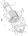
- FIG. 1 is an external perspective view showing a waterproof device 1 according to one embodiment of the present invention.
- the waterproof device 1 comprises a combination of a plug connector (waterproof connector) 10 and a receptacle connector (target connector) 80, which are adapted to be connected together.
- FIG. 2 is an exploded perspective view showing only the plug connector 10.
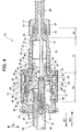
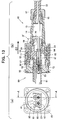
- FIG. 3 a horizontal sectional view showing the plug connector 10 and the receptacle connector 80, taken along an axis of the waterproof device
- FIG. 4 is a vertical sectional view taken along the line B-B in FIG. 3 .
- FIG. 1 shows a state before connection between the plug connector 10 and the receptacle connector 80
- FIGS. 3 and 4 show a state after connection therebetween.
- the receptacle connector 80 may be used, for example, under a condition that it is fixed to a wall (not shown) by a screw (not shown) provided to penetrate through a screw hole 85 formed therein.
- an O-ring 83 may be installed in an annular-shaped recess 92 formed in a R shell 82 thereof. The O-ring 83 makes it possible to close a gap between the wall and the receptacle connector 80 so as to more reliably keep out water.
- the plug connector 10 and the receptacle connector 80 are fixed to each other by a bayonet connection, so as to maintain a connected state therebetween.
- a pair of fixing grooves 90 are formed in an outer surface of a cylindrical portion 86 of the receptacle connector 80 to be located in opposed relation to each other.
- a pair of protrusions 36 are formed on an inner peripheral surface of an end of a joining member 18 of the plug connector 10 to be located in opposed relation to each other.
- the cylindrical portion 86 is formed to protrude toward a connector member 12 while surrounding a periphery of an LC adapter (adapter member) 81 of the receptacle connector 80.
- the protrusions 36 of the joining member 18 are pushed into and along the corresponding ones of the fixing grooves 90 of the cylindrical portion 86 in the arrowed direction "c1" in FIG. 1 , and then the joining member 18 is rotated in the direction "d" in FIG. 1 along an outer surface of the cylindrical portion 86 to allow the protrusions 36 of the joining member 18 to be put into respective recesses 98 of the cylindrical portion 86.
- the LC adapter 81 is provided with four fitting spaces 84.
- Each of the fitting spaces 84 is adapted to allow the connector member 12 of the plug connector 10 and a connector member of the receptacle connector 80 formed in the same configuration as that of the connector member 12 to be fittingly inserted thereinto from opposite sides in such a manner that they are butted against each other.
- a target ferrule (not shown) supported by a connector member (not shown) of the receptacle connector 80 is disposed in a region of the fitting space 84 on the side of the receptacle connector 80, and then the connector member 12 of the plug connector 10 is fitted into a region of the fitting space-84 on the side of the plug connector 10, so that a ferrule 23 supported by the connector member 12 of the plug connector 10 can be butted against the target ferrule through a connection sleeve 91 provided in the LC adapter 81, to establish an optical connection.
- An optical fiber 22 is fixed to an end face of the ferrule 23, while exposing a fiber core thereof.
- the optical fiber 22 is, for example, led out from a jacket 29 of a cable 28 covering it together with a tension member (rigid cord member) 21, to extend inside the connector member 12.
- the plug connector 10 primarily comprises a cord tube (housing body) 14 formed in a cylindrical-shaped body, a plurality of components arranged along the arrowed direction "f" in FIG. 2 and attached to the cord tube 14, such as a rubber hood 11, the connector member 12, an LC knob 62, a scroll wave ring 24 and a holding member 13, and a plurality of components arranged along the arrowed direction "g" in FIG. 2 and attached to the cord tube 14, such as the joining member 18, a fastener 17, a cord clamp 16 and a gasket 15.
- Each of the rubber hood 11, the gasket 15, the cord clamp 16 and the fastener 17 is formed in a generally cylindrical shape in conformity to the cord tube 14.
- the connector member 12 is shown as a type including two connector members 12a, 12b each having the same configuration, by way of example. Alternatively, the number of connector members may be only one, or may be three or more.
- Each of the connector members 12a, 12b has the same configuration as that of a conventional commercially-available LC connector. This means that the present invention can be widely used in the conventional LC connector.
- the connector segment 12 (12a, 12b) has a cantilever beam portion (lock operation portion) 61 (61a, 61b) formed to extend rearwardly and obliquely upwardly.
- the cantilever beam portion 61 (61a, 61b) has a lock protrusion 73 (73a, 73b) formed on a lateral surface thereof.
- the lock protrusion 73 (73a, 73b) is adapted, when the connector member 12 is fitted into the LC adapter 81, to be latched by a complementary shaped portion of the LC adapter 81 (a corresponding one of two concave-shaped lock portions provided in the LC adapter 81 (indicated by the reference numeral 87 in FIG. 11 )), to allow the connector member 12 to be locked. This makes it possible to maintain butting between the ferrule 23 and the target ferrule.
- the lock by the cantilever beam portion 61 is automatically achieved by allowing the connector member 12 to be moved closer to the LC adapter 81, without a particular operation. More specifically, along with an operation of inserting the cantilever beam portion 61 (61a, 61b) into the fitting or receiving space 84 (84a, 84b) (see FIG. 3 ) of the LC adapter 81, The cantilever beam portion 61 (61a, 61b) is automatically displaced downwardly through a collision with the LC adapter 81.
- the cantilever beam portion 61 (61a, 61b) is automatically returned upwardly to automatically lock the connector member 12.
- the cantilever beam portion 61 (61a, 61b) is automatically returned upwardly to automatically lock the connector member 12.
- it is necessary to pulling the connector member 12 out of the LC adapter 81, while displacing the cantilever beam portion 61 (61a, 61b) downwardly by an external operation to release the locked state between the LC adapter 12 and the lock protrusion 73 (73a, 73b) of the connector member 12.
- the downward displacement of the cantilever beam portion 61 is performed through a manual operation by a user.
- the LC knob (unlocking means) 62 is provided in such a manner as to be automatically operated in conjunction with movement of other members to perform the downward displacement, as described in detail later.
- the plug connector 10 in this embodiment can be connected to the receptacle connector 80 and released from the connection with the receptacle connector 80, through a single-step operation.
- the connector member 12 (12a, 12b) is coupled to the LC knob 62 in such a manner as to be freely moved within a given distance along a butting direction of the ferrule and the target ferrule (a fitting direction of the connector member 12 and the LC adapter 81). More specifically, in order to couple the connector member 12 to the LC knob 62 in a freely movable manner, a certain level of play is provided between the gasket 15 and the connector member 12.
- the LC knob 62 generally comprises a flange 65 provided on a front side thereof, and a tubular portion 75 provided on a rear side thereof.
- a rear surface of the flange 65 is in contact with the scroll wave ring 24 as an elastic member disposed between the LC knob 62 and the cord tube 14, so that the LC knob 62 is constantly biased frontwardly, i.e., in a direction causing the fitting between the connector member 12 and the LC adapter 81.
- the flange 65 of the LC knob 62 is formed with a through-hole 69 communicated with an inside of the tubular portion 75.
- a rear end region 68 of the connector member 12 is inserted into and supported by the through-hole 69 and the tubular portion 75.
- the connector member 12 can be freely moved with respect to the LC knob 62 along the fitting direction of the connector member 12 and the LC adapter 81, while being inserted into and supported by the through-hole 69 and the tubular portion 75.
- a frontward movement (i.e., a movement toward the receptacle connector 80) of the connector member 12 is restricted through a collision between a plate-shaped collision spacer 64 provided at a rear end of the connector member 12 and a rear wall 74 of the LC knob 62 defining a rear opening of the through-hole 69.
- a rearward movement (i.e., a movement toward a side opposite to the receptacle connector 80) of the connector member 12 is restricted through a collision between a protrusion 66 provided on a lower region of an outer surface of the connector member 12 and a front wall 72 of the LC knob 62 defining a front opening of the through-hole 69.
- the collision spacer 64 can be attached to the connector member 12 in the arrowed direction "e", as shown in FIG. 2 .
- the LC knob 62 has a tab 67 provided on a front side of an upper portion of the flange 65.
- the tab 67 is formed to protrude frontwardly and have a front end region protruding downwardly, i.e., toward the cantilever beam portion 61, so that the tab 67 generally has a shape capable of wrapping around a free end of the cantilever beam portion 61.
- the cord tube 14 can be classified into a small-diameter portion 50, an intermediate-diameter portion 51, and a large-diameter portion 52, for convenience of explanation.
- the small-diameter portion 50 has the gasket 15, the cord clamp 16 and the fastener 17 which are attached thereto while allowing the cable 28 to penetrate therethrough. This makes it possible to achieve a more reliable waterproof structure.
- a rear end of the small-diameter portion 50 is formed to have an increased inner diameter.
- the gasket 15 is inserted into the increased-diameter portion, and the cord clamp 16 is attached to compress the gasket 15 having the cable 28 penetrating therethrough.
- the fastener 17 is attached to compress an elastic portion 58 provided at a rear end of the cord clamp 16, to reduce a diameter of the elastic portion 58.
- a rear end of the fastener 17 is formed as a tapered portion 57 having an inner diameter which gradually decreases toward a rear edge thereof, so that the elastic portion 58 is compressed by the tapered portion 57, to allow the cable 28 to be fixed.
- a positioning cutout (not shown) may be formed in an inner wall of the small radius portion 50, and correspondingly a positioning protrusion 56 may be formed on the cord clamp 16.
- the intermediate-diameter portion 51 is formed and arranged to support the tubular portion 75 of the LC knob 62.
- the tubular portion 75 has an outer diameter approximately equal to an inner diameter of the intermediate-diameter portion 51.
- the cord tube 14 supports the LC knob 62 while allowing the LC knob 62 to be slidingly moved within a given distance along the butting direction of the ferrule 23 and the target ferrule (along the arrowed direction "c" in FIG. 2 ).
- the plate-shaped holding member 13 is received in the intermediate-diameter portion 51.
- the holding member 13 has an outer diameter less than an inner diameter of the intermediate-diameter portion 51, so that the holding member 13 is fully inserted into the intermediate-diameter portion 51.
- the holding member 13 is provided with a slit 63 which allows an end of the tension member 21 to be inserted thereinto.
- the tension member 21 can be inserted into the slit 63, and fixed to the holding member 13 using a screw (not shown) provided to penetrate through a screw hole 26 formed therein.
- the tension member 21 is fixed to the holding member 13 in the above manner.
- a rear surface 45 of the holding member 13 is brought into contact with an inner wall 47 of a rear end of the cord tube 14, so that a pulling force can be transmitted to the cord tube 14 to reduce a force to be applied to the optical fiber 22.
- a rear plate 35 of the joining member 18 is positioned around a boundary between the intermediate-diameter portion 51 and the large-diameter portion 52, and then a C-shaped retainer member (spring washer) 19 is attached to an outer peripheral surface of a front end of the intermediate-diameter portion 51.
- the retainer member 19 is adapted to collide with the rear plate 35 of the joining member 18 supported by the intermediate-diameter portion 51, to prevent pull-out of the joining member 18 from the intermediate-diameter portion 51.
- the retaining member 19 is elastically fitted into a circular C-shaped concave portion 32 formed in the intermediate-diameter portion 51.
- a C-shaped spring washer (coupling member) 20 is attached to an inner peripheral surface of the front end of the intermediate-diameter portion 51 at a position adjacent to an inner surface the retainer member 19.
- the spring washer 20 is elastically attached as with the retainer member 19.
- the spring washer 20 is disposed to extend over a space 60 defined by an annular-shaped outer concave portion 30 formed in an outer wall 38 of the tubular portion 75 of the LC knob 62 and an annular-shaped inner concave portion 33 formed in an inner wall 39 of the cord tube 14, to couple the LC knob 62 and the cord tube 14 together.
- the annular-shaped outer concave portion 30 and the annular-shaped inner concave portion 33 define two recesses communicated in a direction intersecting with the butting direction (in the arrowed direction "h" in FIG. 4 ).
- the annular-shaped outer concave portion 30 defines a recess having a length greater than that of the spring washer 20 in the butting direction (the arrowed direction "c").
- the recess of the annular-shaped outer concave portion 30 having such a length allows the LC knob 62 to be slidingly moved within a given distance with respect to the cord tube 14.
- a part of a rear end of the intermediate-diameter portion 51 is formed as a pair of flat portions 53 located in opposed relation to each other to perform a tightening operation using a tool such as a spanner.
- the fastener 17 is also formed with a pair of flat portions.
- the large-diameter portion 52 has a tubular portion 25 formed to protrude toward the cylindrical portion 86 of the receptacle connector 80 along the butting direction.
- the connector member 12, and the flange 65 of the LC knob 62 coupled to the connector member 12, can be slidingly moved inside the tubular portion 25 within a given distance along the butting direction.
- the tubular portion 25 can be brought into contact with an inner peripheral surface 97 of the cylindrical portion 86 to form an overlapping region 88 with the cylindrical portion 86 along the butting direction.
- the formation of the overlapping region 88 makes it possible to more effectively keep out water.
- the joining member 18 after penetrating the intermediate- diameter portion 51 is freely fitted onto the large-diameter portion 52.
- the joining member 18 is a generally cylindrical-shaped member which protrudes toward the receptacle connector 80 along the butting direction of the ferrule 23 and the target ferrule and covers an outer periphery of the large-diameter portion 52.
- the joining member 18 is connected to the cylindrical portion 86 of the receptacle connector 80 by the bayonet connection, in the aforementioned manner.
- the cylindrical portion 86 of the receptacle connector 80 is disposed while being inserted into a gap 99 defined between the joining member 18 and the tubular portion 25 of the plug connector 10.
- the joining member 18 can cover an outer peripheral surface 96 of the cylindrical portion 86 and form an overlapping region 87 with the cylindrical portion 86 along the butting direction, as with the tubular portion 25. This makes it possible to reliably keep out water.
- the rubber hood 11 provided in the gap 99 defined between the joining member and the large-diameter portion 52 can also enhance the waterproof effect.
- the rubber hood 11 is positioned in such a manner that it is received in an annular-shaped positioning recess 54 formed in the tubular portion 25, and a rear surface thereof is butted against a flange 27 of the tubular portion 25 constituting a part of the large-diameter portion 52.
- a raised portion 41 formed at a front end of the rubber hood 11 is brought into close contact with a thin-walled region 89 of the cylindrical portion 86, so that the gap can be more reliably closed.
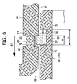
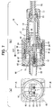
- FIGS. 5(a) to 12 show a sequence of operation for connecting the plug connector 10 to the receptacle connector 80, i.e., a sequence of operation for fitting the connector member 12 into the LC adapter 81.
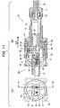
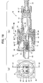
- FIGS. 13(a) to 20 show a sequence of operation for releasing the connection between the plug connector 10 and the receptacle connector 80, i.e., a sequence of operation for pulling the connector member 12 away from the LC adapter 81.
- the figure suffixed with (a) indicates a section line in the vertical sectional view of the figure suffixed with (b), and shows a state during the operation of connecting the plug connector 10 to the receptacle connector 80 (fitting the connector member 12 into the LC adapter 81, for convenience of illustration.
- each component is defined by a common reference numeral or code. For example, a position of the line A-A indicated in FIG. 5(a) is the same as that of the line A-A indicated in FIG.
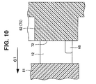
- FIGS. 6 , 8 , 10 , 12 , 14 , 16 , 18 and 20 are fragmentary enlarged views of respective regions shown in FIGS. 5(b) , 7(b) , 9(b) , 11 (b) , 13(b), 15(b) , 17(b) and 19(b) . More specifically, FIG. 6 is a fragmentary enlarged view of a region B in FIG. 5(b) , and FIG. 8 is a fragmentary enlarged view of a region C in FIG. 7 (b) . FIG. 10 is a fragmentary enlarged view of a region E in FIG.
- FIG. 12 is a fragmentary enlarged view of a region G in FIG. 11(b) .
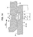
- FIG. 14 is a fragmentary enlarged view of a region H in FIG. 13(b)
- FIG. 16 is a fragmentary enlarged view of a region I in FIG. 15(b)
- FIG. 18 is a fragmentary enlarged view of a region J in FIG. 17(b) .
- FIG. 20 is a fragmentary enlarged view of a region K in FIG. 19(b)
- the connector member 12 in the operation of connecting the plug connector 10 to the receptacle connector 80, the connector member 12 can be fitted into the LC adapter 81, and the joining member 18 can be connected to the cylindrical portion 87 (or fixed to the cylindrical portion 87 by a bayonet connection), through a single-step operation of moving the cord tube 14 with respect to the connector member 12. Further, in the operation of releasing the connection between the plug connector 10 and the receptacle connector 80, the bayonet connection between the joining member 18 and the cylindrical portion 86 can be released, and the fitting between the connector member 12 and the LC adapter 18 can be released, through a single-step operation of moving the cord tube 14 with respect to the connector member 12.
- the plug connector 10 can be connected to the receptacle connector 80, and the connection therebetween can be released, through a single-step operation.
- the unlocking of the connector member 12 provided in the plug connector 10 can be achieved only by a "pull-out operation".
- the waterproof device according to the above embodiment has excellent operating efficiency.
- the fitting between the connector member 12 and the LC adapter 81 can be released in a usual manner, although it is performed using the LC knob 62. This also provides an advantage of being able to facilitate checking the release of the locked state.
- the present invention can be applied to not only a waterproof connector but also various other types of connectors.
Landscapes
- Physics & Mathematics (AREA)
- General Physics & Mathematics (AREA)
- Optics & Photonics (AREA)
- Connector Housings Or Holding Contact Members (AREA)
- Mechanical Coupling Of Light Guides (AREA)
Applications Claiming Priority (1)
| Application Number | Priority Date | Filing Date | Title |
|---|---|---|---|
| JP2009044378A JP4743724B2 (ja) | 2009-02-26 | 2009-02-26 | 防水コネクタ、及び、この防水コネクタを用いた防水装置 |
Publications (3)
| Publication Number | Publication Date |
|---|---|
| EP2253977A2 true EP2253977A2 (de) | 2010-11-24 |
| EP2253977A3 EP2253977A3 (de) | 2011-07-13 |
| EP2253977B1 EP2253977B1 (de) | 2012-05-09 |
Family
ID=42631033
Family Applications (1)
| Application Number | Title | Priority Date | Filing Date |
|---|---|---|---|
| EP20100001857 Not-in-force EP2253977B1 (de) | 2009-02-26 | 2010-02-23 | Wasserfester Steckverbinder und wasserfeste Vorrichtung, die diesen Steckverbinder einsetzt |
Country Status (5)
| Country | Link |
|---|---|
| US (1) | US8628252B2 (de) |
| EP (1) | EP2253977B1 (de) |
| JP (1) | JP4743724B2 (de) |
| CN (1) | CN101820118B (de) |
| AT (1) | ATE557308T1 (de) |
Cited By (2)
| Publication number | Priority date | Publication date | Assignee | Title |
|---|---|---|---|---|
| TWI486655B (zh) * | 2012-07-27 | 2015-06-01 | Japan Aviation Electron | 插頭及光接頭連接體 |
| US9502824B2 (en) | 2014-05-23 | 2016-11-22 | Itt Manufacturing Enterprises, Llc | Electrical connector |
Families Citing this family (52)
| Publication number | Priority date | Publication date | Assignee | Title |
|---|---|---|---|---|
| EP3978974B1 (de) | 2009-09-28 | 2025-02-19 | TE Connectivity Nederland B.V. | Dichtungsgehäuse für einen verbinder an einem kabel wie z. b. einem standardisierten glasfaserverbinder |
| EP2355286B1 (de) | 2010-01-29 | 2019-04-03 | CommScope Connectivity Belgium BVBA | Kabelabdichtungs- und Befestigungsvorrichtung |
| EP2355283A1 (de) | 2010-01-29 | 2011-08-10 | Tyco Electronics Raychem BVBA | Kabelabdichtungsvorrichtung, Kabelabschluss und Befestigungsvorrichtung |
| US8727636B2 (en) * | 2010-03-19 | 2014-05-20 | Corning Incorporated | Fiber optic interface device with positionable cleaning cover |
| JP5707808B2 (ja) * | 2010-09-21 | 2015-04-30 | 富士通株式会社 | 結合デバイス |
| JP5505228B2 (ja) * | 2010-09-24 | 2014-05-28 | 富士通株式会社 | 光コネクタ |
| JP5616466B2 (ja) * | 2011-02-04 | 2014-10-29 | 株式会社フジクラ | 端子台 |
| US8764308B2 (en) * | 2011-06-06 | 2014-07-01 | Panduit Corp. | Duplex clip assembly for fiber optic connectors |
| CN103123408B (zh) * | 2011-11-21 | 2015-04-15 | 鸿富锦精密工业(深圳)有限公司 | 防水光纤连接器及其光纤插头和光纤适配器 |
| DE102012202225B4 (de) * | 2012-02-14 | 2015-10-22 | Te Connectivity Germany Gmbh | Steckergehäuse mit Dichtung |
| HUE031727T2 (en) | 2012-06-26 | 2017-07-28 | Huawei Tech Co Ltd | Optical fiber connector, optical fiber adaptor and optical fiber connector assembly |
| US20140060927A1 (en) * | 2012-08-30 | 2014-03-06 | Avc Industrial Corp. | Hook-thread component and wiring element fastening device having the hook-thread component |
| JP5866734B2 (ja) * | 2012-12-27 | 2016-02-17 | ヒロセ電機株式会社 | コネクタ、このコネクタを用いたコネクタ装置、及びこのコネクタに用いるコネクタ部材 |
| KR101330648B1 (ko) | 2013-05-22 | 2013-11-18 | 주식회사 케이오티 | 다심 mt 페룰을 이용한 옥외용 광커넥터 어셈블리 |
| US9235010B2 (en) * | 2013-06-28 | 2016-01-12 | Commscope Technologies Llc | Robust optical crimp connector |
| KR101513850B1 (ko) * | 2013-10-16 | 2015-04-21 | 전자부품연구원 | 구조가 개선된 방수형 광커넥터 |
| US10048447B2 (en) * | 2013-10-31 | 2018-08-14 | CommScope Connectivity Belgium BVBA | Fiber optic connection system |
| KR101512997B1 (ko) * | 2014-01-03 | 2015-04-17 | 주식회사 제이티 | 이중 락킹 구조의 방수형 광커넥터 |
| KR101560140B1 (ko) | 2014-01-13 | 2015-10-14 | 주식회사 제이티 | 방수형 광커넥터 |
| CN109343178A (zh) | 2014-02-07 | 2019-02-15 | 泰科电子公司 | 硬化的光功率连接系统 |
| CA2887523C (en) * | 2014-04-14 | 2017-08-29 | Fujikura, Ltd. | Optical connector |
| CN104348036B (zh) * | 2014-10-21 | 2017-07-14 | 河南天海电器有限公司 | 新型连接器 |
| CN204359965U (zh) * | 2014-11-20 | 2015-05-27 | 泰科电子(上海)有限公司 | 连接器系统 |
| US9755382B2 (en) * | 2015-03-13 | 2017-09-05 | Senko Advanced Components, Inc. | Connector system with interchangeable connector modules for optical fibers, electrical conductors, or both |
| US10288820B2 (en) | 2015-04-03 | 2019-05-14 | CommScope Connectivity Belgium BVBA | Low cost hardened fiber optic connection system |
| US9897766B2 (en) | 2015-07-02 | 2018-02-20 | Senko Advanced Components, Inc. | Bayonet lock MPO connector |
| WO2017003934A1 (en) | 2015-07-02 | 2017-01-05 | Senko Advanced Components, Inc. | Bayonet lock mpo connector |
| US11175466B2 (en) * | 2015-07-02 | 2021-11-16 | Senko Advanced Components, Inc. | Bayonet lock MPO connector |
| US9726831B2 (en) * | 2015-07-02 | 2017-08-08 | Senko Advanced Components, Inc. | Bayonet lock MPO connector |
| JP2017090657A (ja) * | 2015-11-10 | 2017-05-25 | ヒロセ電機株式会社 | 光ファイバケーブル付コネクタ |
| US9869828B2 (en) * | 2016-05-18 | 2018-01-16 | Canon U.S.A, Inc. | Apparatus and method for remotely engaging and disengaging a connector |
| MX2019003561A (es) * | 2016-09-30 | 2020-01-21 | Huawei Tech Co Ltd | Enchufe de fibra optica, adaptador de fibra optica y ensamblaje de conector de fibra optica. |
| CN108023205A (zh) * | 2016-10-31 | 2018-05-11 | 全亿大科技(佛山)有限公司 | 防水连接器及其组装方法 |
| US10128607B2 (en) * | 2017-02-23 | 2018-11-13 | Te Connectivity Corporation | Sealed connector system |
| US10295759B2 (en) | 2017-05-18 | 2019-05-21 | Senko Advanced Components, Inc. | Optical connector with forward-biasing projections |
| CN109286100B (zh) * | 2017-07-21 | 2021-06-04 | 泰科电子(上海)有限公司 | 电连接器 |
| EP3460548A1 (de) * | 2017-09-25 | 2019-03-27 | Fujikura Ltd. | Klemmelement, optischer stecker und herstellungsverfahren des optischen steckers |
| US10444442B2 (en) | 2017-11-03 | 2019-10-15 | Senko Advanced Components, Inc. | MPO optical fiber connector |
| FI3677938T3 (fi) * | 2017-12-28 | 2023-10-09 | Fujikura Ltd | Optinen liitin ja menetelmä optisen liittimen kytkemiseksi |
| JP2019140046A (ja) * | 2018-02-15 | 2019-08-22 | 住友電装株式会社 | コネクタ、コネクタ装置 |
| US11041993B2 (en) | 2018-04-19 | 2021-06-22 | Senko Advanced Components, Inc. | Fiber optic adapter with removable insert for polarity change and removal tool for the same |
| US10921528B2 (en) | 2018-06-07 | 2021-02-16 | Senko Advanced Components, Inc. | Dual spring multi-fiber optic connector |
| US10522946B1 (en) * | 2018-09-17 | 2019-12-31 | Hewlett Packard Enterprise Development Lp | Connectors with locking tab |
| CN111596415B (zh) * | 2019-02-20 | 2022-04-26 | 利佳科技股份有限公司 | 连接器系统 |
| US20220239036A1 (en) * | 2019-05-24 | 2022-07-28 | Nokia Shanghai Bell Co., Ltd. | Communication System Connector |
| CN114207494A (zh) * | 2019-08-08 | 2022-03-18 | 扇港元器件有限公司 | 用于户外级连接器组件的推拉机构 |
| US11353664B1 (en) | 2019-08-21 | 2022-06-07 | Senko Advanced Components, Inc. | Fiber optic connector |
| CN114787677A (zh) | 2019-11-13 | 2022-07-22 | 扇港元器件有限公司 | 光纤连接器 |
| IT202000001519A1 (it) * | 2020-01-27 | 2021-07-27 | Prysmian Spa | Un gruppo adattatore per connettore ottico |
| CN111679376B (zh) * | 2020-04-23 | 2022-05-17 | 中航光电科技股份有限公司 | 连接器 |
| CN114690340B (zh) * | 2022-02-14 | 2026-01-16 | 大连光洋科技集团有限公司 | 一种可让sfp光模块用在潮湿环境的防水结构 |
| CN114883841B (zh) * | 2022-04-22 | 2026-01-13 | 东莞市维康汽车电子有限公司 | 防水型射频连接器及其组装方法 |
Citations (2)
| Publication number | Priority date | Publication date | Assignee | Title |
|---|---|---|---|---|
| US20020006253A1 (en) | 1997-11-13 | 2002-01-17 | Marchi Silverio De | Plug construction for an optical plug-and-socket connection |
| WO2008128940A1 (en) | 2007-04-20 | 2008-10-30 | Huber + Suhner Ag | Optical connector |
Family Cites Families (10)
| Publication number | Priority date | Publication date | Assignee | Title |
|---|---|---|---|---|
| GB9307488D0 (en) * | 1993-04-08 | 1993-06-02 | Amp Holland | Optical fibre connector latching mechanism |
| JP3362014B2 (ja) * | 1999-06-29 | 2003-01-07 | エヌイーシートーキン株式会社 | ケーブルコネクタのロック、アンロック構造及びロック、アンロック方法 |
| US6565262B2 (en) * | 2000-12-14 | 2003-05-20 | Corning Cable Systems Llc | Trigger mechanism, optical cable connector including same, and method of assembling an optical cable connector |
| JP2004258094A (ja) * | 2003-02-24 | 2004-09-16 | Hitachi Cable Ltd | リリース機構付きパッケージ |
| JP2004318048A (ja) * | 2003-08-22 | 2004-11-11 | Canare Electric Co Ltd | 光コネクタの雌プラグ |
| US7074066B2 (en) * | 2004-03-29 | 2006-07-11 | Tyco Electronics Corporation | Sealed electrical connector having internal latching mechanism therefore |
| US7234877B2 (en) * | 2004-10-27 | 2007-06-26 | Panduit Corp. | Fiber optic industrial connector |
| US7325980B2 (en) * | 2005-08-26 | 2008-02-05 | Tyco Electronics Corporation | Duplex style fiber optic connector interface assembly |
| US7338214B1 (en) * | 2006-08-25 | 2008-03-04 | Tyco Electronics Corporation | Method and apparatus for sealing fiber optic connectors for industrial applications |
| JP4776504B2 (ja) * | 2006-11-15 | 2011-09-21 | 富士通株式会社 | 光コネクタの抜け止め解除補助装置およびプリント基板装置 |
-
2009
- 2009-02-26 JP JP2009044378A patent/JP4743724B2/ja active Active
-
2010
- 2010-02-19 US US12/709,299 patent/US8628252B2/en active Active
- 2010-02-23 AT AT10001857T patent/ATE557308T1/de active
- 2010-02-23 EP EP20100001857 patent/EP2253977B1/de not_active Not-in-force
- 2010-02-24 CN CN2010101261778A patent/CN101820118B/zh not_active Expired - Fee Related
Patent Citations (2)
| Publication number | Priority date | Publication date | Assignee | Title |
|---|---|---|---|---|
| US20020006253A1 (en) | 1997-11-13 | 2002-01-17 | Marchi Silverio De | Plug construction for an optical plug-and-socket connection |
| WO2008128940A1 (en) | 2007-04-20 | 2008-10-30 | Huber + Suhner Ag | Optical connector |
Cited By (2)
| Publication number | Priority date | Publication date | Assignee | Title |
|---|---|---|---|---|
| TWI486655B (zh) * | 2012-07-27 | 2015-06-01 | Japan Aviation Electron | 插頭及光接頭連接體 |
| US9502824B2 (en) | 2014-05-23 | 2016-11-22 | Itt Manufacturing Enterprises, Llc | Electrical connector |
Also Published As
| Publication number | Publication date |
|---|---|
| US8628252B2 (en) | 2014-01-14 |
| JP2010197854A (ja) | 2010-09-09 |
| US20100215322A1 (en) | 2010-08-26 |
| CN101820118A (zh) | 2010-09-01 |
| JP4743724B2 (ja) | 2011-08-10 |
| EP2253977B1 (de) | 2012-05-09 |
| ATE557308T1 (de) | 2012-05-15 |
| CN101820118B (zh) | 2012-11-07 |
| EP2253977A3 (de) | 2011-07-13 |
Similar Documents
| Publication | Publication Date | Title |
|---|---|---|
| US8628252B2 (en) | Waterproof connector and waterproof device using the same | |
| JP6363784B1 (ja) | 光コネクタプラグおよび二連式の光コネクタプラグ | |
| CN100474020C (zh) | 光连接器 | |
| JP4577793B2 (ja) | 防水コネクタ、及び、この防水コネクタを用いた防水装置 | |
| EP2355286B1 (de) | Kabelabdichtungs- und Befestigungsvorrichtung | |
| CN102016670B (zh) | 具有解锁机构的插头连接器 | |
| KR101111452B1 (ko) | 광커넥터 내장 플러그 | |
| EP2037543A1 (de) | Elektrischer Steckverbinder und Steckeranordnung | |
| US20090191750A1 (en) | Connector Assembly Having A Slider Element | |
| JP3307846B2 (ja) | コネクタ | |
| US8708574B2 (en) | Safeguard device for an interface of a fibre adapter | |
| RU2011139493A (ru) | Оптический разъем для концевой заделки оптоволокна | |
| WO2013042000A1 (en) | Fiber optic connector with shutter | |
| CN105137547B (zh) | 一种光纤连接器及光纤连接器组件 | |
| CN105244678B (zh) | 一种连接器组件及其插座和插座壳体组件 | |
| JP2011107513A (ja) | 防水コネクタ、及び、この防水コネクタを用いた防水装置 | |
| JP2020013010A (ja) | 光コネクタ | |
| JP2020046582A (ja) | Lc用ユニブーツプラグコネクタ | |
| JP5398560B2 (ja) | 光コネクタ及びその組立方法 | |
| JP7457204B2 (ja) | 光コネクタの製造工具 | |
| JP3800606B2 (ja) | 光コネクタアダプタ | |
| CN116755194B (zh) | 一种防水连接器、连接器组件及光纤连接盒 | |
| KR101085093B1 (ko) | 광섬유용 배선기구 | |
| JP2011203682A (ja) | 光コネクタ | |
| JP2008083087A (ja) | 光ファイバー用コンセント |
Legal Events
| Date | Code | Title | Description |
|---|---|---|---|
| PUAI | Public reference made under article 153(3) epc to a published international application that has entered the european phase |
Free format text: ORIGINAL CODE: 0009012 |
|
| AK | Designated contracting states |
Kind code of ref document: A2 Designated state(s): AT BE BG CH CY CZ DE DK EE ES FI FR GB GR HR HU IE IS IT LI LT LU LV MC MK MT NL NO PL PT RO SE SI SK SM TR |
|
| AX | Request for extension of the european patent |
Extension state: AL BA RS |
|
| REG | Reference to a national code |
Ref country code: DE Ref legal event code: R079 Ref document number: 602010001273 Country of ref document: DE Free format text: PREVIOUS MAIN CLASS: G02B0006360000 Ipc: G02B0006380000 |
|
| PUAL | Search report despatched |
Free format text: ORIGINAL CODE: 0009013 |
|
| AK | Designated contracting states |
Kind code of ref document: A3 Designated state(s): AT BE BG CH CY CZ DE DK EE ES FI FR GB GR HR HU IE IS IT LI LT LU LV MC MK MT NL NO PL PT RO SE SI SK SM TR |
|
| AX | Request for extension of the european patent |
Extension state: AL BA RS |
|
| RIC1 | Information provided on ipc code assigned before grant |
Ipc: G02B 6/38 20060101AFI20110606BHEP |
|
| 17P | Request for examination filed |
Effective date: 20110908 |
|
| GRAP | Despatch of communication of intention to grant a patent |
Free format text: ORIGINAL CODE: EPIDOSNIGR1 |
|
| GRAS | Grant fee paid |
Free format text: ORIGINAL CODE: EPIDOSNIGR3 |
|
| GRAA | (expected) grant |
Free format text: ORIGINAL CODE: 0009210 |
|
| AK | Designated contracting states |
Kind code of ref document: B1 Designated state(s): AT BE BG CH CY CZ DE DK EE ES FI FR GB GR HR HU IE IS IT LI LT LU LV MC MK MT NL NO PL PT RO SE SI SK SM TR |
|
| REG | Reference to a national code |
Ref country code: GB Ref legal event code: FG4D |
|
| REG | Reference to a national code |
Ref country code: AT Ref legal event code: REF Ref document number: 557308 Country of ref document: AT Kind code of ref document: T Effective date: 20120515 Ref country code: CH Ref legal event code: EP |
|
| REG | Reference to a national code |
Ref country code: IE Ref legal event code: FG4D |
|
| REG | Reference to a national code |
Ref country code: DE Ref legal event code: R096 Ref document number: 602010001273 Country of ref document: DE Effective date: 20120705 |
|
| REG | Reference to a national code |
Ref country code: SE Ref legal event code: TRGR |
|
| REG | Reference to a national code |
Ref country code: NL Ref legal event code: VDEP Effective date: 20120509 |
|
| REG | Reference to a national code |
Ref country code: DE Ref legal event code: R082 Ref document number: 602010001273 Country of ref document: DE Representative=s name: MUELLER-BORE & PARTNER PATENTANWAELTE, EUROPEA, DE |
|
| REG | Reference to a national code |
Ref country code: LT Ref legal event code: MG4D Effective date: 20120509 |
|
| PG25 | Lapsed in a contracting state [announced via postgrant information from national office to epo] |
Ref country code: PL Free format text: LAPSE BECAUSE OF FAILURE TO SUBMIT A TRANSLATION OF THE DESCRIPTION OR TO PAY THE FEE WITHIN THE PRESCRIBED TIME-LIMIT Effective date: 20120509 Ref country code: LT Free format text: LAPSE BECAUSE OF FAILURE TO SUBMIT A TRANSLATION OF THE DESCRIPTION OR TO PAY THE FEE WITHIN THE PRESCRIBED TIME-LIMIT Effective date: 20120509 Ref country code: NO Free format text: LAPSE BECAUSE OF FAILURE TO SUBMIT A TRANSLATION OF THE DESCRIPTION OR TO PAY THE FEE WITHIN THE PRESCRIBED TIME-LIMIT Effective date: 20120809 Ref country code: FI Free format text: LAPSE BECAUSE OF FAILURE TO SUBMIT A TRANSLATION OF THE DESCRIPTION OR TO PAY THE FEE WITHIN THE PRESCRIBED TIME-LIMIT Effective date: 20120509 Ref country code: IS Free format text: LAPSE BECAUSE OF FAILURE TO SUBMIT A TRANSLATION OF THE DESCRIPTION OR TO PAY THE FEE WITHIN THE PRESCRIBED TIME-LIMIT Effective date: 20120909 Ref country code: CY Free format text: LAPSE BECAUSE OF FAILURE TO SUBMIT A TRANSLATION OF THE DESCRIPTION OR TO PAY THE FEE WITHIN THE PRESCRIBED TIME-LIMIT Effective date: 20120509 |
|
| REG | Reference to a national code |
Ref country code: DE Ref legal event code: R081 Ref document number: 602010001273 Country of ref document: DE Owner name: HIROSE ELECTRIC CO., LTD., JP Free format text: FORMER OWNER: HIROSE ELECTRIC CO., LTD., SUMIDEN HIGH PRECISION CO., LTD, , JP Effective date: 20120914 Ref country code: DE Ref legal event code: R081 Ref document number: 602010001273 Country of ref document: DE Owner name: SEI OPTIFRONTIER CO., LTD., JP Free format text: FORMER OWNER: HIROSE ELECTRIC CO., LTD., SUMIDEN HIGH PRECISION CO., LTD, , JP Effective date: 20120914 Ref country code: DE Ref legal event code: R082 Ref document number: 602010001273 Country of ref document: DE Representative=s name: MUELLER-BORE & PARTNER PATENTANWAELTE, EUROPEA, DE Effective date: 20120914 Ref country code: DE Ref legal event code: R082 Ref document number: 602010001273 Country of ref document: DE Representative=s name: MUELLER-BORE & PARTNER PATENTANWAELTE PARTG MB, DE Effective date: 20120914 Ref country code: DE Ref legal event code: R081 Ref document number: 602010001273 Country of ref document: DE Owner name: SEI OPTIFRONTIER CO., LTD., YOKOHAMA-SHI, JP Free format text: FORMER OWNER: HIROSE ELECTRIC CO., LTD., SUMIDEN HIGH PRECISION CO., LTD, , JP Effective date: 20120914 Ref country code: DE Ref legal event code: R081 Ref document number: 602010001273 Country of ref document: DE Owner name: SEI OPTIFRONTIER CO., LTD., YOKOHAMA-SHI, JP Free format text: FORMER OWNERS: HIROSE ELECTRIC CO., LTD., TOKYO, JP; SUMIDEN HIGH PRECISION CO., LTD., CHIGASAKI-SHI, KANAGAWA, JP Effective date: 20120914 Ref country code: DE Ref legal event code: R081 Ref document number: 602010001273 Country of ref document: DE Owner name: HIROSE ELECTRIC CO., LTD., JP Free format text: FORMER OWNERS: HIROSE ELECTRIC CO., LTD., TOKYO, JP; SUMIDEN HIGH PRECISION CO., LTD., CHIGASAKI-SHI, KANAGAWA, JP Effective date: 20120914 |
|
| REG | Reference to a national code |
Ref country code: AT Ref legal event code: MK05 Ref document number: 557308 Country of ref document: AT Kind code of ref document: T Effective date: 20120509 |
|
| PG25 | Lapsed in a contracting state [announced via postgrant information from national office to epo] |
Ref country code: PT Free format text: LAPSE BECAUSE OF FAILURE TO SUBMIT A TRANSLATION OF THE DESCRIPTION OR TO PAY THE FEE WITHIN THE PRESCRIBED TIME-LIMIT Effective date: 20120910 Ref country code: HR Free format text: LAPSE BECAUSE OF FAILURE TO SUBMIT A TRANSLATION OF THE DESCRIPTION OR TO PAY THE FEE WITHIN THE PRESCRIBED TIME-LIMIT Effective date: 20120509 Ref country code: SI Free format text: LAPSE BECAUSE OF FAILURE TO SUBMIT A TRANSLATION OF THE DESCRIPTION OR TO PAY THE FEE WITHIN THE PRESCRIBED TIME-LIMIT Effective date: 20120509 Ref country code: GR Free format text: LAPSE BECAUSE OF FAILURE TO SUBMIT A TRANSLATION OF THE DESCRIPTION OR TO PAY THE FEE WITHIN THE PRESCRIBED TIME-LIMIT Effective date: 20120810 Ref country code: LV Free format text: LAPSE BECAUSE OF FAILURE TO SUBMIT A TRANSLATION OF THE DESCRIPTION OR TO PAY THE FEE WITHIN THE PRESCRIBED TIME-LIMIT Effective date: 20120509 |
|
| REG | Reference to a national code |
Ref country code: FR Ref legal event code: CA Effective date: 20121026 Ref country code: FR Ref legal event code: TP Owner name: SEI OPTIFRONTIER CO.LTD., JP Effective date: 20121026 Ref country code: FR Ref legal event code: CD Owner name: SEI OPTIFRONTIER CO.LTD., JP Effective date: 20121026 |
|
| REG | Reference to a national code |
Ref country code: GB Ref legal event code: 732E Free format text: REGISTERED BETWEEN 20121115 AND 20121121 |
|
| PG25 | Lapsed in a contracting state [announced via postgrant information from national office to epo] |
Ref country code: BE Free format text: LAPSE BECAUSE OF FAILURE TO SUBMIT A TRANSLATION OF THE DESCRIPTION OR TO PAY THE FEE WITHIN THE PRESCRIBED TIME-LIMIT Effective date: 20120509 |
|
| PG25 | Lapsed in a contracting state [announced via postgrant information from national office to epo] |
Ref country code: RO Free format text: LAPSE BECAUSE OF FAILURE TO SUBMIT A TRANSLATION OF THE DESCRIPTION OR TO PAY THE FEE WITHIN THE PRESCRIBED TIME-LIMIT Effective date: 20120509 Ref country code: EE Free format text: LAPSE BECAUSE OF FAILURE TO SUBMIT A TRANSLATION OF THE DESCRIPTION OR TO PAY THE FEE WITHIN THE PRESCRIBED TIME-LIMIT Effective date: 20120509 Ref country code: DK Free format text: LAPSE BECAUSE OF FAILURE TO SUBMIT A TRANSLATION OF THE DESCRIPTION OR TO PAY THE FEE WITHIN THE PRESCRIBED TIME-LIMIT Effective date: 20120509 Ref country code: SK Free format text: LAPSE BECAUSE OF FAILURE TO SUBMIT A TRANSLATION OF THE DESCRIPTION OR TO PAY THE FEE WITHIN THE PRESCRIBED TIME-LIMIT Effective date: 20120509 Ref country code: NL Free format text: LAPSE BECAUSE OF FAILURE TO SUBMIT A TRANSLATION OF THE DESCRIPTION OR TO PAY THE FEE WITHIN THE PRESCRIBED TIME-LIMIT Effective date: 20120509 Ref country code: CZ Free format text: LAPSE BECAUSE OF FAILURE TO SUBMIT A TRANSLATION OF THE DESCRIPTION OR TO PAY THE FEE WITHIN THE PRESCRIBED TIME-LIMIT Effective date: 20120509 Ref country code: AT Free format text: LAPSE BECAUSE OF FAILURE TO SUBMIT A TRANSLATION OF THE DESCRIPTION OR TO PAY THE FEE WITHIN THE PRESCRIBED TIME-LIMIT Effective date: 20120509 |
|
| REG | Reference to a national code |
Ref country code: FR Ref legal event code: TQ Owner name: HIROSE ELECTRIC CO., LTD., JP Effective date: 20130205 Ref country code: FR Ref legal event code: TQ Owner name: SEI OPTIFRONTIER CO.LTD., JP Effective date: 20130205 |
|
| PLBE | No opposition filed within time limit |
Free format text: ORIGINAL CODE: 0009261 |
|
| STAA | Information on the status of an ep patent application or granted ep patent |
Free format text: STATUS: NO OPPOSITION FILED WITHIN TIME LIMIT |
|
| 26N | No opposition filed |
Effective date: 20130212 |
|
| PG25 | Lapsed in a contracting state [announced via postgrant information from national office to epo] |
Ref country code: ES Free format text: LAPSE BECAUSE OF FAILURE TO SUBMIT A TRANSLATION OF THE DESCRIPTION OR TO PAY THE FEE WITHIN THE PRESCRIBED TIME-LIMIT Effective date: 20120820 |
|
| REG | Reference to a national code |
Ref country code: DE Ref legal event code: R097 Ref document number: 602010001273 Country of ref document: DE Effective date: 20130212 |
|
| PG25 | Lapsed in a contracting state [announced via postgrant information from national office to epo] |
Ref country code: BG Free format text: LAPSE BECAUSE OF FAILURE TO SUBMIT A TRANSLATION OF THE DESCRIPTION OR TO PAY THE FEE WITHIN THE PRESCRIBED TIME-LIMIT Effective date: 20120809 |
|
| PG25 | Lapsed in a contracting state [announced via postgrant information from national office to epo] |
Ref country code: MC Free format text: LAPSE BECAUSE OF NON-PAYMENT OF DUE FEES Effective date: 20130228 |
|
| REG | Reference to a national code |
Ref country code: IE Ref legal event code: MM4A |
|
| PG25 | Lapsed in a contracting state [announced via postgrant information from national office to epo] |
Ref country code: IE Free format text: LAPSE BECAUSE OF NON-PAYMENT OF DUE FEES Effective date: 20130223 |
|
| PGFP | Annual fee paid to national office [announced via postgrant information from national office to epo] |
Ref country code: SE Payment date: 20140211 Year of fee payment: 5 Ref country code: DE Payment date: 20140226 Year of fee payment: 5 |
|
| PGFP | Annual fee paid to national office [announced via postgrant information from national office to epo] |
Ref country code: IT Payment date: 20140205 Year of fee payment: 5 Ref country code: FR Payment date: 20131227 Year of fee payment: 5 |
|
| PG25 | Lapsed in a contracting state [announced via postgrant information from national office to epo] |
Ref country code: MT Free format text: LAPSE BECAUSE OF FAILURE TO SUBMIT A TRANSLATION OF THE DESCRIPTION OR TO PAY THE FEE WITHIN THE PRESCRIBED TIME-LIMIT Effective date: 20120509 |
|
| PGFP | Annual fee paid to national office [announced via postgrant information from national office to epo] |
Ref country code: GB Payment date: 20140106 Year of fee payment: 5 |
|
| REG | Reference to a national code |
Ref country code: CH Ref legal event code: PL |
|
| PG25 | Lapsed in a contracting state [announced via postgrant information from national office to epo] |
Ref country code: CH Free format text: LAPSE BECAUSE OF NON-PAYMENT OF DUE FEES Effective date: 20140228 Ref country code: LI Free format text: LAPSE BECAUSE OF NON-PAYMENT OF DUE FEES Effective date: 20140228 |
|
| PG25 | Lapsed in a contracting state [announced via postgrant information from national office to epo] |
Ref country code: SM Free format text: LAPSE BECAUSE OF FAILURE TO SUBMIT A TRANSLATION OF THE DESCRIPTION OR TO PAY THE FEE WITHIN THE PRESCRIBED TIME-LIMIT Effective date: 20120509 |
|
| PG25 | Lapsed in a contracting state [announced via postgrant information from national office to epo] |
Ref country code: TR Free format text: LAPSE BECAUSE OF FAILURE TO SUBMIT A TRANSLATION OF THE DESCRIPTION OR TO PAY THE FEE WITHIN THE PRESCRIBED TIME-LIMIT Effective date: 20120509 |
|
| PG25 | Lapsed in a contracting state [announced via postgrant information from national office to epo] |
Ref country code: LU Free format text: LAPSE BECAUSE OF NON-PAYMENT OF DUE FEES Effective date: 20130223 Ref country code: HU Free format text: LAPSE BECAUSE OF FAILURE TO SUBMIT A TRANSLATION OF THE DESCRIPTION OR TO PAY THE FEE WITHIN THE PRESCRIBED TIME-LIMIT; INVALID AB INITIO Effective date: 20100223 Ref country code: MK Free format text: LAPSE BECAUSE OF FAILURE TO SUBMIT A TRANSLATION OF THE DESCRIPTION OR TO PAY THE FEE WITHIN THE PRESCRIBED TIME-LIMIT Effective date: 20120509 |
|
| REG | Reference to a national code |
Ref country code: DE Ref legal event code: R119 Ref document number: 602010001273 Country of ref document: DE |
|
| REG | Reference to a national code |
Ref country code: SE Ref legal event code: EUG |
|
| GBPC | Gb: european patent ceased through non-payment of renewal fee |
Effective date: 20150223 |
|
| REG | Reference to a national code |
Ref country code: FR Ref legal event code: ST Effective date: 20151030 |
|
| PG25 | Lapsed in a contracting state [announced via postgrant information from national office to epo] |
Ref country code: SE Free format text: LAPSE BECAUSE OF NON-PAYMENT OF DUE FEES Effective date: 20150224 |
|
| PG25 | Lapsed in a contracting state [announced via postgrant information from national office to epo] |
Ref country code: IT Free format text: LAPSE BECAUSE OF NON-PAYMENT OF DUE FEES Effective date: 20150223 |
|
| PG25 | Lapsed in a contracting state [announced via postgrant information from national office to epo] |
Ref country code: GB Free format text: LAPSE BECAUSE OF NON-PAYMENT OF DUE FEES Effective date: 20150223 Ref country code: DE Free format text: LAPSE BECAUSE OF NON-PAYMENT OF DUE FEES Effective date: 20150901 |
|
| PG25 | Lapsed in a contracting state [announced via postgrant information from national office to epo] |
Ref country code: FR Free format text: LAPSE BECAUSE OF NON-PAYMENT OF DUE FEES Effective date: 20150302 |