EP2254077A1 - Dispositif pour carte à puce conventionnelle permettant une transaction électronique à travers un réseau - Google Patents
Dispositif pour carte à puce conventionnelle permettant une transaction électronique à travers un réseau Download PDFInfo
- Publication number
- EP2254077A1 EP2254077A1 EP09305453A EP09305453A EP2254077A1 EP 2254077 A1 EP2254077 A1 EP 2254077A1 EP 09305453 A EP09305453 A EP 09305453A EP 09305453 A EP09305453 A EP 09305453A EP 2254077 A1 EP2254077 A1 EP 2254077A1
- Authority
- EP
- European Patent Office
- Prior art keywords
- communication
- card
- terminal
- smart card
- conventional smart
- Prior art date
- Legal status (The legal status is an assumption and is not a legal conclusion. Google has not performed a legal analysis and makes no representation as to the accuracy of the status listed.)
- Withdrawn
Links
Images

Classifications
-
- G—PHYSICS
- G06—COMPUTING OR CALCULATING; COUNTING
- G06K—GRAPHICAL DATA READING; PRESENTATION OF DATA; RECORD CARRIERS; HANDLING RECORD CARRIERS
- G06K19/00—Record carriers for use with machines and with at least a part designed to carry digital markings
- G06K19/06—Record carriers for use with machines and with at least a part designed to carry digital markings characterised by the kind of the digital marking, e.g. shape, nature, code
- G06K19/067—Record carriers with conductive marks, printed circuits or semiconductor circuit elements, e.g. credit or identity cards also with resonating or responding marks without active components
- G06K19/07—Record carriers with conductive marks, printed circuits or semiconductor circuit elements, e.g. credit or identity cards also with resonating or responding marks without active components with integrated circuit chips
- G06K19/077—Constructional details, e.g. mounting of circuits in the carrier
- G06K19/07749—Constructional details, e.g. mounting of circuits in the carrier the record carrier being capable of non-contact communication, e.g. constructional details of the antenna of a non-contact smart card
-
- G—PHYSICS
- G06—COMPUTING OR CALCULATING; COUNTING
- G06K—GRAPHICAL DATA READING; PRESENTATION OF DATA; RECORD CARRIERS; HANDLING RECORD CARRIERS
- G06K19/00—Record carriers for use with machines and with at least a part designed to carry digital markings
- G06K19/06—Record carriers for use with machines and with at least a part designed to carry digital markings characterised by the kind of the digital marking, e.g. shape, nature, code
- G06K19/067—Record carriers with conductive marks, printed circuits or semiconductor circuit elements, e.g. credit or identity cards also with resonating or responding marks without active components
- G06K19/07—Record carriers with conductive marks, printed circuits or semiconductor circuit elements, e.g. credit or identity cards also with resonating or responding marks without active components with integrated circuit chips
- G06K19/0701—Record carriers with conductive marks, printed circuits or semiconductor circuit elements, e.g. credit or identity cards also with resonating or responding marks without active components with integrated circuit chips at least one of the integrated circuit chips comprising an arrangement for power management
-
- G—PHYSICS
- G06—COMPUTING OR CALCULATING; COUNTING
- G06K—GRAPHICAL DATA READING; PRESENTATION OF DATA; RECORD CARRIERS; HANDLING RECORD CARRIERS
- G06K19/00—Record carriers for use with machines and with at least a part designed to carry digital markings
- G06K19/06—Record carriers for use with machines and with at least a part designed to carry digital markings characterised by the kind of the digital marking, e.g. shape, nature, code
- G06K19/067—Record carriers with conductive marks, printed circuits or semiconductor circuit elements, e.g. credit or identity cards also with resonating or responding marks without active components
- G06K19/07—Record carriers with conductive marks, printed circuits or semiconductor circuit elements, e.g. credit or identity cards also with resonating or responding marks without active components with integrated circuit chips
- G06K19/077—Constructional details, e.g. mounting of circuits in the carrier
- G06K19/07737—Constructional details, e.g. mounting of circuits in the carrier the record carrier consisting of two or more mechanically separable parts
- G06K19/07741—Constructional details, e.g. mounting of circuits in the carrier the record carrier consisting of two or more mechanically separable parts comprising a first part operating as a regular record carrier and a second attachable part that changes the functional appearance of said record carrier, e.g. a contact-based smart card with an adapter part which, when attached to the contact card makes the contact card function as a non-contact card
Definitions
- the invention relates to a method for performing transactions across a network using smart cards and terminals.
- the invention relates to a method for carrying out such transactions through a telecommunications network by means of smart cards and telecommunication terminals.
- the invention has many applications in monetary transactions, the electronic purse, transactions relating to health, games.
- the telecommunications networks concerned are all networks that can be borrowed by a telephone subscriber to access another subscriber or services.
- These networks include telephony networks, switched network or integrated services network and the cellular network.
- Some telecommunication terminals are equipped or adapted to have two chip card reading interfaces, one for communicating with a subscriber identity chip card dedicated to telephony such as for example a SIM card ( Subscriber Identity Module ) in the case of the cellular telecommunications system and the other for a smart card called application card dedicated to one or more applications other than telephony.
- a subscriber identity chip card dedicated to telephony such as for example a SIM card ( Subscriber Identity Module ) in the case of the cellular telecommunications system and the other for a smart card called application card dedicated to one or more applications other than telephony.
- SIM card Subscriber Identity Module
- application card dedicated to one or more applications other than telephony.
- This may be for example a card electronic wallet type or debit card and / or credit.
- Smart cards dedicated to one or more applications other than telephony can be delivered by independent operators. It is therefore necessary that such telecommunication terminals support application command sets dedicated to different types of application cards (for example a banking application, a loyalty application).
- This type of solution requires an adaptation of a terminal so that it can communicate with two cards. This solution can be expensive. It also requires an adaptation of the subscriber identification card so that it has a set of commands for controlling the additional card.
- subscriber identification smart cards can directly host applications other than dedicated to telephony.
- this solution makes it possible to overcome the aforementioned drawbacks, it raises other difficulties related in particular to the fact that the subscriber identification card is the property of a mobile telephone operator and that it is therefore necessary to reach an agreement. between said operator and the third party operating said specific bank or other application.
- NFC Near Field Communication in English
- a shop the payment of a transport ticket
- the entering information from an advertising poster identification to allow access etc.
- One of the objectives of a proximity communication protocol is notably to simplify the connectivity for the user while guaranteeing a secure transaction.
- the transmission power is decidedly very low in order to overcome the use of a source of energy at communicating objects.
- the NFC technique guarantees a form of security through the use of encoding and encryption offered by said protocol.
- Three modes are defined to use the NFC technique: the so-called card emulation mode, the reader mode and the Peer-to-Peer mode.
- a subscriber identity card Subscriber Identity Module
- SWP Single Wire Protocol
- the reader mode allows a user, such as a communication terminal, to read information emanating for example from passive electronic tags by approaching his communication terminal on posters, on parcels or on business cards.
- "Peer-to-Peer" mode allows a communication terminal to exchange information with another communication terminal such as, for example, files or contacts according to the principle similar to that proposed by Bluetooth for example .
- the NFC technique currently offers a bit rate of 424 kbps in a frequency band of 13.56 MHz at a maximum distance of 10 cm.
- NFC communications rely on the reader to transmit power to the radio-read chip.
- a subscriber identification card of a telephony terminal SWP communication protocol can read and use an application card having an antenna for implementing a contactless communication type OSI 14443 in particular.
- a transport card using contactless communication can easily be credited by means of the subscriber identification card.
- said transport card does not have any means of providing electrical energy such as a battery. The power required for communication is delivered by the communication terminal via the radio signals delivered by the one.
- the aim of the invention is to solve the aforementioned drawbacks by allowing a device to adapt a conventional smart card so that it can communicate with a customer identity card capable of implementing a data protection protocol. proximity communication, such as the SWP protocol without having to adapt said conventional card and the communication terminal.
- the means for controlling the communication can also provide a power supply necessary for the operation of the conventional smart card from radio signals received from a terminal so that said card can respond to the requests of said terminal.
- the device may further comprise rectifying means for transforming a portion of the radio signals received into a continuous signal for charging energy storage means capable of delivering a power supply necessary for the operation of the conventional smart card. so that said card can respond to requests from a terminal.
- the energy storage means can additionally supply a power supply necessary for the operation of the communication control means.
- said energy storage means may comprise a capacitance.
- Such a device may further comprise means for determining the level of available energy to ensure the operation of the control means of the communication and / or the conventional smart card.
- the means for determining the energy level can thus transmit an alert information to the communication control means when the energy level reaches a predetermined minimum threshold.
- the communication control means can interpret the alerting information delivered by the means to determine the level of available energy and can transmit a request to the terminal to time the communication flow and allow the storage means to recover a level of energy higher than the predetermined minimum threshold.
- the communication control means may comprise an electronic computer capable of implementing the " Near Field Communication " technique.
- the figure 1 discloses a so-called conventional smart card 1 composed of a card body 3 generally made of plastic on which we can find graphical indications specific to a bank operator for example and to user. So according to the figure 1 , the body 3 bears on the one hand an inscription "General Bank” to signify that it is a bank card issued by the bank “General Bank” and a "John Smith” inscription specific to the user of the card 1. According to the example illustrated in connection with the figure 1 , the body 3 has a unique card number "1231 4567 8967 1326" and a validity date "08/12".
- the body of a conventional smart card may include a cutout 3a allowing, if necessary, to reduce the surface of the card body to insert it into small size readers.
- the conventional card 1 comprises a module 2 protecting a microcontroller not shown. Said module 2 further comprises a series of electrical contacts 2a. Each contact is connected to the microcontroller in order to transmit electrical signals such as a supply voltage necessary for the operation of the card, a clock, data signals, etc.
- a conventional smart card thus differs from a so-called “contactless” smart card by the presence of said electrical contacts in place of an antenna.
- a conventional smart card 1 generally communicates with a reader by means of a communication protocol defined by a standard such as the OSI 7816 standard.
- the reader comprises an interface of the electrical contacts type able to establish a physical and direct communication with the contacts 2a.
- a conventional smart card generally communicates with a reader by means of a communication protocol defined by a standard such as the OSI 7816 standard.
- the reader comprises an interface of the electrical contacts type able to establish a physical and direct communication with the contacts 2a.
- the figure 2 illustrates an example of known communication between a mobile phone type communication terminal 10 and a communicating electronic object such as a passive electrical tag or a contactless smart card.
- a mobile telephone 10 comprises a subscriber identity module 11 in the form of a conventional smart card dedicated to a subscriber, generally known by the term SIM ( Subscriber Identity Module ).
- SIM Subscriber Identity Module
- Said card 11 is connected to an unrepresented input-output interface of the terminal 10.
- the smart card 11 mainly contains a microcontroller, a ROM ( Read Only Memory ) memory including a system specific communication, application and authentication algorithms.
- Said microcontroller also comprises a non-volatile memory, for example of EEPROM type ( Electrically-Erasable Programmable Read-Only Memory ) which contains all the characteristics related to the subscriber, in particular the international identity of the subscriber IMSI ( International Mobile Subscriber Identity ).
- EEPROM type Electrically-Erasable Programmable Read-Only Memory
- IMSI International Mobile Subscriber Identity
- the communication terminal 10 further comprises a communication interface 12 for controlling the communication with the outside world to said terminal according to a communication protocol without proximity contact.
- said interface 12 is an NFC interface implementing the reader mode.
- the terminal can thus communicate with a communicating object in the form of a passive electronic tag or a contactless smart card.
- the object 20 thus comprises an antenna 21 connected to a microcontroller 22 making it possible to transmit or even receive radio messages conforming, for example, to the international standard OSI 14443.
- the subscriber identification card 11 supports the SWP communication protocol serving to ensure the physical link between the card 11 and the NFC interface 12 of the communication terminal. 10.
- the requests to the object 20 emanating from the card 11 according to the protocol 13 SWP are translated into radio signals 30 by the interface 12 NFC.
- the responses of the object 20 in the form of radio signals 30 are translated by the NFC interface 12 of the terminal into SWP protocol messages directly interpretable by the subscriber identification card 11.
- the subscriber identification card 10 may control a transaction, for example a transport, for crediting tickets from a remote server to a contactless transport card 20 through a communication terminal 10.
- the invention provides according to the figure 3 , a device 40 capable of interfacing with a conventional smart card 1.
- the main function of said device is to enable said card 1 to communicate with a subscriber identity card 11 such as that described in connection with the figure 2 .
- the device 40 comprises a housing 41 able to receive all or part of a conventional smart card in order to keep the latter in communication, in particular in accordance with two variant embodiments respectively presented by the Figures 4 and 5 . So according to the figure 3 , the device 40 can be likened to a card holder whose body has an opening 42 for inserting a conventional card 1 in a housing 41.
- the device 40 can take any format likely to allow it to interface with a conventional card 1 regardless of the format and size thereof.
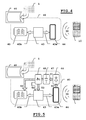
- the figure 4 presents a first embodiment of a device 40 according to the invention.
- the device 40 comprises a communication interface in the form of a series of electrical contacts 45 able to provide an electrical connection with the electrical contacts 2a of a conventional smart card 1 as described in figure 1 .
- the latter can thus communicate according to a communication protocol 43b of the OSI 7816 type with a microcontroller 43.
- the latter is also connected to means 44 of the antenna or coil type for transmitting and / or receiving radio signals 43a to and / or from a communication terminal 10 according to a communication protocol without proximity contact.
- the microcontroller 43 thus controls the communication between said means for transmitting and / or receiving 44 and the communication terminal 10.
- a communication terminal 10 approaches a conventional smart card 1 as described in connection with the figure 1 , said smart card being inserted into a device 40 according to the invention as illustrated by the figure 3 .
- the field 30 generated by the communication terminal 10 wakes the microcontroller 43 of the device 40 under the action of the antenna 44.
- the field 30 allows said microcontroller 43 to meet its electrical needs to ensure its operation.
- said field 30 delivers enough energy to the microcontroller 43 so that the latter can also sufficiently power the card 1 by means of the electrical contacts 2a and 45.
- the smart card 1 can also be awake and transmit a response 43b intended to presented to the microcontroller 43.
- the microcontroller 43 translates said response into radio signals 43a conveyed by the field 30 to the NFC interface of the terminal.
- the microcontroller 43 is able to implement the mode Card emulation of the NFC technique.
- the interface 12 of the communication terminal transmits the presentation message of the smart card 1 to the subscriber identity card 11 by means of the SWP protocol.
- the card 11 can trigger application processing by means of proactive commands to a remote application server or to the smart card 1 using the SWP protocol.
- the smart card 1 although conventional, can communicate with a terminal and / or a subscriber identity card according to the prior art and be at the center of an electronic transaction with an application server. remote.
- the communication between the conventional card 1 and the microcontroller, the operation of said card may sometimes require an electrical energy greater than that delivered by the microcontroller 43.
- the figure 5 illustrates a preferred embodiment in which the device 40 further comprises means capable of delivering a power supply necessary for the operation of the conventional smart card 1 so that said card can respond to the demands of a communication terminal 10 .
- a device 40 further comprises rectifying means 46 for transforming a portion 50 of the radio signals received through the field 30 into a continuous signal 51 for charging energy storage means 47.
- said means Energy storage includes one or more tank capacities.
- the means 47 are thus able to deliver a supply voltage to the conventional smart card 1 or even to the microcontroller 43.
- the application example described in connection with FIG. figure 4 is thus perpetuated by the addition of means 46 and 47.
- a device 40 according to the invention may further comprise means 48 for determining the energy level available and available in particular by the energy storage means 47.
- means 48 for determining the energy level can transmit alert information 54 to the microcontroller 43 when the energy level reaches a predetermined minimum threshold.
- the microcontroller 43 responsible for controlling the communication can interpret the alerting information 54 delivered and send a request to the communication terminal 10 to delay the communication flow and allow the storage means 47 to recover a level of communication. energy above the predetermined minimum threshold.
- the conventional card 1 can be put to sleep.
- a plurality of thresholds can be used, a threshold for the needs of the conventional smart card, another for the microcontroller and so on.
- the invention has also been described in connection with a preferred application putting in a situation a communication terminal of the mobile phone type capable of implementing an electronic transaction through a telecommunication network.
- the terminal is a banking type terminal with which it is possible to perform electronic transactions carried out through a network for example operated by a banking operator.
- a terminal is able to implement commands to a server of a bank for example, and to a conventional chip card debit and / or credit as described in connection with the figure 1 , said card being inserted beforehand into a card-carrying device according to the invention and as represented in FIG. figure 3 .
- the latter communicates with the terminal in a mode similar to that described in connection with the Figures 4 and 5 .
- a banking terminal is substituted for the mobile telephone 10 represented on the said Figures 4 and 5 .
- the bank terminal can be located in an agency of a bank or directly to a merchant for example.
- the banking terminal can be replaced by a laptop or any other electronic device, for example PDA type adapted to act as a terminal communicating with a card holder device according to the invention.
Landscapes
- Engineering & Computer Science (AREA)
- Computer Hardware Design (AREA)
- Microelectronics & Electronic Packaging (AREA)
- Physics & Mathematics (AREA)
- General Physics & Mathematics (AREA)
- Theoretical Computer Science (AREA)
- Mobile Radio Communication Systems (AREA)
Abstract
L'invention concerne un dispositif pour adapter une carte à puce conventionnelle pour que celle-ci puisse communiquer par exemple avec une carte d'identité d'abonné d'un terminal disposant d'une interface de communication sans contact de proximité conforme à l'art antérieur afin de pouvoir mettre en oeuvre une transaction électronique à travers un réseau de télécommunication.
Description
- L'invention concerne un procédé pour effectuer des transactions à travers un réseau au moyen de cartes à puce et de terminaux. De manière préférée l'invention concerne un procédé pour effectuer de telles transactions à travers un réseau de télécommunications au moyen de cartes à puce et de terminaux de télécommunication.
- Elle concerne plus particulièrement un dispositif permettant de mettre en oeuvre le procédé. L'invention trouve de nombreuses applications dans les transactions monétaires, le porte-monnaie électronique, les transactions relatives à la santé, aux jeux.
- Les réseaux de télécommunications concernés sont tous les réseaux susceptibles d'être empruntés par un abonné du téléphone pour accéder à un autre abonné ou à des services.
- Parmi ces réseaux on peut citer les réseaux de téléphonie, réseau commuté ou réseau à intégration de services et le réseau de téléphonie cellulaire.
- Certains terminaux de télécommunication sont équipés ou adaptés pour disposer de deux interfaces de lecture de cartes à puce, l'une pour communiquer avec une carte à puce d'identification d'abonné dédiée à la téléphonie telle que par exemple une carte SIM (Subscriber Identity Module) dans le cas du système de télécommunication cellulaire et l'autre pour une carte à puce dite carte applicative dédiée à une ou plusieurs applications autres que la téléphonie. Il pourra s'agir par exemple d'une carte de type portemonnaie électronique ou carte de débit et/ou de crédit.
- Les cartes à puce dédiées à une ou plusieurs applications autres que la téléphonie peuvent être délivrées par des opérateurs indépendants. Il s'avère nécessaire par conséquent que de tels terminaux de télécommunication supportent des jeux de commandes applicatifs dédiés à différents types de cartes applicatives (par exemple une application bancaire, une application de fidélité).
- Ceci est particulièrement contraignant pour les prestataires de services qui doivent de ce fait établir des liens et accords avec à des fabricants de terminaux pour proposer leurs applications à leurs clients.
- De plus, cela impose une limitation dans le choix des cartes applicatives utilisables avec un terminal de télécommunication donné, à celles qui auront été prévues initialement sous peine d'avoir à modifier les logiciels du terminal.
- Pour palier à cet inconvénient une solution décrite notamment en liaison avec le document
EP1032925 permet de ne pas alourdir les interfaces logiques de communication d'un terminal tout en lui permettant d'accepter toute carte applicative en introduisant des moyens de communication à toute carte d'identification d'abonné dédiée à la téléphonie pour lui permettre de piloter toute carte applicative à travers le terminal de télécommunication. - Ce type de solution nécessite toutefois une adaptation d'un terminal afin qu'il puisse communiquer avec deux cartes. Cette solution peut s'avérer couteuse. Elle nécessite également une adaptation de la carte d'identification d'abonné pour qu'elle dispose d'un jeu de commandes destinées à piloter la carte additionnelle.
- Pour palier à cet inconvénient, des cartes à puce d'identification d'abonné permettent d'héberger directement des applications autres que dédiées à la téléphonie. Bien que cette solution permette de s'affranchir des inconvénients précités, elle soulève d'autres difficultés liées notamment au fait que la carte d'identification d'abonné est la propriété d'un opérateur de téléphonie mobile et qu'il faille donc une entente entre ledit opérateur et le tiers opérant ladite application spécifique bancaire ou autre.
- L'avènement de nouvelles techniques telles le NFC (Near Field Communication en langue anglaise) ouvre la porte à de multiples applications utilisant un téléphone mobile. Nous pouvons citer à titre d'exemples non limitatifs le paiement dans un magasin, le paiement d'un ticket de transport, la saisie d'une information à partir d'une affiche publicitaire, l'identification pour permettre un accès etc. Un des objectifs d'un protocole de communication de proximité est notamment de simplifier la connectivité pour l'utilisateur tout en garantissant une transaction sécurisée. Selon la technique NFC, la puissance d'émission est résolument très faible afin de s'affranchir de l'utilisation d'une source d'énergie au niveau des objets communicants. Ainsi l'échange d'information entre deux appareils communiquant ne peut s'effectuer qu'à une distance maximale de l'ordre d'une dizaine de centimètres. La technique NFC garantie une forme de sécurité par l'usage d'un encodage et d'un chiffrement offerts par ledit protocole. Trois modes sont définis pour utiliser la technique NFC : le mode dit d'émulation de carte, le mode lecteur et le mode « Peer-to-Peer ».
- Le mode d'émulation de carte permet d'émuler le fonctionnement d'une carte à puce sans contact de crédit par exemple pour assurer notamment une fonction de sécurité. Selon cette technique une carte d'identification d'abonné (Subscriber Identity Module), dispose de moyens lui permettant de mettre en oeuvre un protocole tel le SWP (Single Wire Protocol) servant à assurer le lien physique entre la carte et une interface NFC du terminal de communication utilisée pour le contrôle des communications.
- Le mode lecteur permet à un utilisateur, tel un terminal de communication, de lire des informations émanant par exemple d'étiquettes électroniques passives en approchant son terminal de communication sur des affiches, sur des colis ou sur des cartes de visites. Le mode « Peer-to-Peer », permet à un terminal de communication d'échanger des informations avec un autre terminal de communication comme, par exemple, des fichiers ou des contacts selon le principe similaire à celui proposé par la technologie Bluetooth par exemple.
- La technique NFC offre à ce jour un débit de 424 kbps dans une bande de fréquence de 13,56 Mhz à une distance maximum de 10 cm. A la différence de la technologie RFID (Radio Frequency IDentification), les communications NFC s'appuient sur le lecteur pour transmettre la puissance à la puce lue par radiofréquence.
- Ainsi il est possible et connu à ce jour de doter une carte d'identification d'abonné d'un terminal de téléphonie du protocole de communication SWP. Une telle carte peut lire et exploiter une carte applicative disposant d'une antenne pour mettre en oeuvre une communication sans contact de type OSI 14443 notamment. Une carte de transport par exemple utilisant une communication sans contact peut ainsi facilement être créditée au moyen de la carte d'identification d'abonné. En outre, ladite carte de transport ne dispose pas de moyens fournisseurs d'énergie électrique tels une batterie. La puissance nécessaire à la communication est délivrée par la par le terminal de communication via les signaux radioélectriques délivrés par celui.
- Toutefois, un grand nombre de cartes bancaires dites conventionnelles de type débit et/ou crédit ne dispose pas à ce jour de la fonction sans contact mais nécessite une communication « filaire » normalisée, telle que définie notamment par la norme OSI 7816, avec un lecteur au moyen d'un module et de contacts électriques. Ainsi pour mettre en oeuvre actuellement une transaction de paiement au moyen par exemple d'un terminal de télécommunication et d'une carte de débit/crédit conventionnelle, il est nécessaire que le terminal puisse disposer de deux interfaces conformément à ce que préconise le document
EP1032925 notamment. - L'invention vise à résoudre les inconvénients cités précédemment en permettant au moyen d'un dispositif d'adapter une carte à puce conventionnelle pour que celle-ci puisse communiquer avec une carte d'identité d'abonnée apte à mettre en oeuvre un protocole de communication de proximité, tel le protocole SWP sans avoir à adapter ladite carte conventionnelle et le terminal de communication.
- A cette fin, il est prévu un dispositif porte-carte apte à interfacer avec une carte à puce conventionnelle comportant
- des moyens pour émettre et/ou recevoir des signaux radioélectriques à destination et/ou en provenance d'un terminal selon un protocole de communication sans contact de proximité ;
- des moyens pour contrôler la communication entre lesdits moyens pour émettre et/ou recevoir et le terminal, aptes à traduire :
- des signaux radioélectriques reçus en commandes interprétables par la carte à puce conventionnelle ;
- des réponses de ladite carte à puce conventionnelle en signaux radioélectriques.
- Selon un mode de réalisation, les moyens pour contrôler la communication peuvent délivrer en outre une alimentation électrique nécessaire au fonctionnement de la carte à puce conventionnelle à partir de signaux radioélectriques reçus depuis un terminal afin que ladite carte puisse répondre aux sollicitations dudit terminal.
- L'invention prévoit que le dispositif puisse comporter en outre des moyens de redressement pour transformer une partie des signaux radioélectriques reçus en signal continu pour charger des moyens de stockage d'énergie aptes à délivrer une alimentation électrique nécessaire au fonctionnement de la carte à puce conventionnelle afin que ladite carte puisse répondre aux sollicitations d'un terminal.
- Selon ce mode de réalisation les moyens de stockage d'énergie peuvent délivrer en outre une alimentation nécessaire au fonctionnement des moyens de contrôle de la communication. A titre, d'exemple l'invention prévoit que lesdits moyens de stockage d'énergie puissent comporter une capacité.
- Un tel dispositif peut comporter en outre des moyens pour déterminer le niveau d'énergie disponible permettant d'assurer le fonctionnement des moyens de contrôle de la communication et/ou de la carte à puce conventionnelle. Les moyens pour déterminer le niveau d'énergie peuvent ainsi transmettre une information d'alerte aux moyens de contrôle de la communication lorsque le niveau d'énergie atteint un seuil minimal prédéterminé.
- Selon ce mode de réalisation, il peut être prévu que les moyens de contrôle de la communication puissent interpréter l'information d'alerte délivrée par les moyens pour déterminer le niveau d'énergie disponible et puissent transmettre une requête à destination du terminal pour temporiser le flux de communication et permettre aux moyens de stockage de recouvrer un niveau d'énergie supérieur au seuil minimal prédéterminé.
- L'invention prévoit que selon une réalisation préférée, les moyens de contrôle de la communication puissent comporter un calculateur électronique apte à mettre en oeuvre la technique « Near Field Communication ».
- D'autres caractéristiques et avantages apparaîtront plus clairement à la lecture de la description qui suit et à l'examen des figures qui l'accompagnent parmi lesquelles :
- la
figure 1 présente une carte à puce conventionnelle de type carte de débit/crédit ; - la
figure 2 décrit un terminal de communication communiquant avec une étiquette électronique passive selon une technique connue ; - la
figure 3 présente un mode de réalisation d'un dispositif conforme à l'invention ; - les
figures 4 et 5 illustrent respectivement un schéma fonctionnel de réalisation d'un dispositif conforme à l'invention selon deux modes de réalisation préférée. - La
figure 1 décrit une carte à puce 1 dite conventionnelle composée d'un corps de carte 3 généralement en matière plastique sur lequel on peut retrouver des indications graphiques propres à un opérateur bancaire par exemple et à utilisateur. Ainsi selon lafigure 1 , le corps 3 porte d'une part une inscription « General Bank » pour signifier qu'il s'agit d'une carte bancaire délivrée par la banque « General Bank » ainsi qu'une inscription « John Smith » propre à l'utilisateur de la carte 1. Selon l'exemple illustré en liaison avec lafigure 1 , le corps 3 comporte un numéro de carte unique « 1231 4567 8967 1326 » et une date de validité « 08/12 ». Le corps d'une carte à puce conventionnelle peut comporter une découpe 3a permettant le cas échéant de réduire la surface du corps de carte pour l'insérer dans des lecteurs de taille réduite. La carte conventionnelle 1 comporte un module 2 protégeant un microcontrôleur non représenté. Ledit module 2 comprend en outre une série de contacts électriques 2a. Chaque contact est relié au microcontrôleur afin de transmettre des signaux électriques tels une tension d'alimentation nécessaire au fonctionnement de la carte, une horloge, des signaux de données etc. Une carte à puce conventionnelle se distingue ainsi d'une carte à puce dite « sans contact » par la présence desdits contacts électriques en lieu et place d'une antenne. - Une carte à puce conventionnelle 1 communique généralement avec un lecteur au moyen d'un protocole de communication défini par une norme telle la norme OSI 7816. Le lecteur comporte une interface de type contacts électriques aptes à établir une communication physique et directe avec les contacts 2a d'une carte à puce conventionnelle.
- La
figure 2 permet d'illustrer un exemple de communication connu entre un terminal de communication de type téléphone mobile 10 et un objet électronique communiquant 20 tel une étiquette électrique passive ou une carte à puce sans contact. Selon cet exemple un téléphone mobile 10 comporte un module d'identité d'abonné 11 sous la forme d'une carte à puce conventionnelle dédiée à un abonné, généralement connu sous le vocable SIM (Subscriber Identity Module). Ladite carte 11 est reliée à une interface d'entrée-sortie non représentée du terminal 10. La carte à puce 11 contient principalement un microcontrôleur, une mémoire de type ROM (Read Only Memory) incluant un système d'exploitation et des algorithmes de communication, d'application et d'authentification spécifiques. Ledit microcontrôleur comporte en outre une mémoire non volatile par exemple de type EEPROM (Electrically-Erasable Programmable Read-Only Memory) qui contient toutes les caractéristiques liées à l'abonné, notamment l'identité internationale de l'abonné IMSI (International Mobile Subscriber Identity). - Le terminal de communication 10 comporte en outre une interface de communication 12 pour contrôler la communication avec le monde extérieur audit terminal selon un protocole de communication sans contact de proximité. A titre d'exemple ladite interface 12 est une interface NFC mettant en oeuvre le mode lecteur. Le terminal peut ainsi entrer en communication avec un objet communiquant 20 sous la forme d'une étiquette électronique passive ou une carte à puce sans contact. L'objet 20 comporte ainsi une antenne 21 reliée à un microcontrôleur 22 permettant d'émettre voire de recevoir des messages radioélectriques conformes par exemple à la norme internationale OSI 14443.
- Pour permettre à la carte 11 d'échanger avec l'objet 20, la carte d'identification d'abonné 11 supporte le protocole de communication SWP servant à assurer le lien physique entre la carte 11 et l'interface NFC 12 du terminal de communication 10. Ainsi les requêtes à destination de l'objet 20 émanant de la carte 11 suivant le protocole 13 SWP sont traduites en signaux radioélectriques 30 par l'interface 12 NFC. Réciproquement les réponses 30 de l'objet 20 sous la forme de signaux radioélectriques 30 sont traduits par l'interface 12 NFC du terminal en messages conformes au protocole SWP directement interprétables par la carte d'identification d'abonné 11.
- Pour pouvoir dialoguer avec un serveur d'applications distant (non représenté), la carte d'identification d'abonné 11 est dite proactive c'est-à-dire apte à déclencher des actions dans le terminal de communication 10 au moyen par exemple de commandes pré-formatées suivant un protocole de communication de type « T=0 » défini par la norme OSI 7816-3 et encapsulées selon les recommandations du standard GSM 11.14 généralement connues sous le vocable « SIM - Toolkit ».
- Ainsi, la carte d'identification d'abonné 10 peut piloter une transaction par exemple de transport permettant de créditer des titres de transport depuis un serveur distant vers une carte de transport 20 sans contact au travers d'un terminal de communication 10.
- Il existe aujourd'hui très peu de cartes à puce de type débit et/ou crédit supportant la fonction de communication sans contact. La très grande majorité de ce type de carte sont des cartes conventionnelles nécessitant une connexion physique avec une interface de communication au moyen de contacts électriques comme illustré en lien avec la
figure 1 . - Pour palier à ce fait, l'invention prévoit selon la
figure 3 , un dispositif 40 apte à interfacer avec une carte à puce conventionnelle 1. La fonction principale dudit dispositif est de permettre à ladite carte 1 de communiquer avec une carte d'identité d'abonné 11 telle que celle décrite en liaison avec lafigure 2 . - Le dispositif 40 comporte un logement 41 apte à recevoir tout ou partie d'une carte à puce conventionnelle afin de maintenir celle-ci en communication conformément notamment à deux variantes de réalisation présentées respectivement par les
figures 4 et 5 . Ainsi selon lafigure 3 , le dispositif 40 peut s'apparenter à un porte-carte dont le corps comporte une ouverture 42 permettant d'insérer une carte conventionnelle 1 dans un logement 41. Le dispositif 40 peut prendre tout format de nature à lui permettre d'interfacer avec une carte conventionnelle 1 quels que soient le format et la taille de celle-ci. - La
figure 4 présente un premier mode de réalisation d'un dispositif 40 conforme à l'invention. - Ainsi le dispositif 40 comporte une interface de communication sous la formes d'une séries de contacts électriques 45 aptes à assurer une liaison électrique avec les contacts électriques 2a d'une carte à puce conventionnelle 1 telle que décrite en
figure 1 . Cette dernière peut ainsi communiquer selon un protocole de communication 43b du type OSI 7816 avec un microcontrôleur 43. Ce dernier est par ailleurs connecté à des moyens 44 du type antenne ou bobine pour émettre et/ou recevoir des signaux radioélectriques 43a à destination et/ou en provenance d'un terminal de communication 10 selon un protocole de communication sans contact de proximité. Le microcontrôleur 43 contrôle ainsi la communication entre lesdits moyens pour émettre et/ou recevoir 44 et le terminal de communication 10. - Ledit microcontrôleur 43 traduit ainsi :
- des signaux radioélectriques reçus 43a en commandes 43b interprétables par la carte à puce conventionnelle 1;
- des réponses 43b de ladite carte à puce conventionnelle 1 en signaux radioélectriques 43a.
- Selon un exemple d'application, un terminal de communication 10, tel que décrit en lien avec la
figure 2 , s'approche d'une carte à puce conventionnelle 1 telle que décrite en lien avec lafigure 1 , ladite carte à puce étant insérée dans un dispositif 40 conforme à l'invention tel qu'illustré par lafigure 3 . Le champ 30 généré par le terminal de communication 10 réveille le microcontrôleur 43 du dispositif 40 sous l'action de l'antenne 44. Le champ 30 permet audit microcontrôleur 43 de survenir à ses besoins électriques pour assurer son fonctionnement. Selon lafigure 4 , ledit champ 30 délivre suffisamment d'énergie au microcontrôleur 43 pour que ce dernier puisse également alimenter suffisamment la carte 1 au moyen des contacts électriques 2a et 45. Ainsi la carte à puce 1 peut aussi être réveillée et transmettre une réponse 43b destinée à se présenter au microcontrôleur 43. Ce dernier traduit ladite réponse en signaux radioélectriques 43a acheminées par le champ 30 à l'interface NFC du terminal. A titre d'exemple pour réaliser cette opération de traduction le microcontrôleur 43 est apte à mettre en oeuvre le mode émulation de carte de la technique NFC. A son tour l'interface 12 du terminal de communication transmet le message de présentation de la carte à puce 1 à la carte d'identité d'abonnée 11 au moyen du protocole SWP. A ce stade, la carte 11 peut déclencher un traitement applicatif au moyen de commandes proactives à destination d'un serveur d'applications distant ou à destination de la carte à puce 1 au moyen du protocole SWP. Ainsi grâce à l'invention la carte à puce 1 bien que conventionnelle peut communiquer avec un terminal et/ou une carte d'identité d'abonnée selon l'art antérieur et être au centre d'une transaction électronique avec un serveur d'application distant. - La communication entre la carte conventionnelle 1 et le microcontrôleur, le fonctionnement de ladite carte peuvent parfois nécessiter une énergie électrique supérieure à celle délivrée par le microcontrôleur 43. Aussi la
figure 5 permet d'illustrer un mode de réalisation préférée dans lequel le dispositif 40 comporte en outre des moyens aptes à délivrer une alimentation électrique nécessaire au fonctionnement de la carte à puce conventionnelle 1 afin que ladite carte puisse répondre aux sollicitations d'un terminal de communication 10. - Ainsi un dispositif 40 comporte en outre des moyens de redressement 46 pour transformer une partie 50 des signaux radioélectriques reçus au travers du champ 30 en un signal continu 51 pour charger des moyens de stockage d'énergie 47. A titre d'exemple, lesdits moyens de stockage d'énergie comportent une ou plusieurs capacités réservoir. Les moyens 47 sont ainsi aptes à délivrer une tension d'alimentation à la carte à puce conventionnelle 1 voire au microcontrôleur 43. L'exemple d'application décrit en lien avec la
figure 4 est ainsi pérennisé par l'adjonction des moyens 46 et 47. - Selon une variante de réalisation, un dispositif 40 conforme à l'invention peut comporter en outre des moyens 48 pour déterminer le niveau d'énergie disponible et livrable notamment par les moyens de stockage d'énergie 47. Lesdits moyens 48 pour déterminer le niveau d'énergie peuvent transmettre une information d'alerte 54 au microcontrôleur 43 lorsque le niveau d'énergie atteint un seuil minimal prédéterminé. Ainsi le microcontrôleur 43 chargé du contrôle de la communication peut interpréter l'information d'alerte 54 délivrée et transmettre une requête à destination du terminal de communication 10 pour temporiser le flux de communication et permettre aux moyens de stockage 47 de recouvrer un niveau d'énergie supérieur au seuil minimal prédéterminé. Durant le temps de « recharge » des moyens de stockage, la carte conventionnelle 1 peut être mise en sommeil. Selon l'invention une pluralité de seuils peut être utilisée, un seuil pour les besoins de la carte à puce conventionnelle, un autre pour le microcontrôleur etc.
- Pour pouvoir temporiser le flux de communication, l'invention prévoit que le microcontrôleur 43 puisse transmettre des signaux électriques 43a dédiés à une requête de suspension provisoire de communication à destination du terminal de communication 10. En variante, une telle requête peut se traduire par des paramètres de communication transmis au moyen du champ 30 permettant de ralentir voire d'accélérer le flux. Il peut par ailleurs également s'agir de codes de contrôle véhiculés par le champ 30 et conformes au protocole OSI 14443 destinés à cette fin. Ainsi le microcontrôleur 43 remplit l'intégralité de son rôle de contrôle de la communication :
- en maitrisant le flux de communication afin de disposer de l'énergie suffisante au fonctionnement de la carte à puce conventionnelle et ;
- en traduisant les messages et réponses d'une carte à puce conventionnelle dialoguant selon un premier protocole dit « filaire » de type OSI 7816 en signaux radioélectriques tels que définis par exemple par le standard OSI 14443.
- L'invention a été décrite selon un mode de réalisation préférée utilisant la technique NFC permettant une communication sans contact de proximité. Toutefois, l'invention ne serait être limitée par ladite technique.
- En outre l'invention a été également décrite en liaison avec une application préférée mettant en situation un terminal de communication du type téléphone mobile apte à mettre en oeuvre une transaction électronique au travers d'un réseau de télécommunication.
- Selon une autre application, le terminal est un terminal de type bancaire à l'aide duquel il est possible d'effectuer des transactions électroniques réalisées au travers d'un réseau par exemple opéré par un opérateur bancaire. Dans ce cas, un tel terminal est apte à mettre en oeuvre des commandes à destination d'un serveur d'une banque par exemple, et à destination d'une carte à puce conventionnelle de débit et/ou crédit telle que décrite en liaison avec la
figure 1 , ladite carte étant insérée au préalable dans un dispositif porte-carte conforme à l'invention et tel que représenté enfigure 3 . Ce dernier communique avec le terminal selon un mode analogue à celui décrit en liaison avec lesfigures 4 et 5 . - Selon cette autre application, un terminal bancaire est substitué au téléphone mobile 10 représenté sur lesdites
figures 4 et 5 . Le terminal bancaire peut être situé au sein d'une agence d'une banque ou directement chez un commerçant par exemple. - Selon une troisième application, le terminal bancaire peut être remplacé par un ordinateur portable ou tout autre appareil électronique par exemple de type PDA apte à assurer le rôle d'un terminal communiquant avec un dispositif porte-carte conforme à l'invention.
Claims (8)
- Dispositif porte-carte (40) apte à interfacer (45) avec une carte à puce conventionnelle (1) caractérisé en ce qu'il comporte :- des moyens pour émettre et/ou recevoir (44) des signaux radioélectriques (43a) à destination et/ou en provenance d'un terminal (10) selon un protocole de communication sans contact de proximité ;- des moyens (43) pour contrôler la communication entre lesdits moyens pour émettre et/ou recevoir et le terminal, aptes à traduire :- des signaux radioélectriques reçus (43a) en commandes (43b) interprétables par la carte à puce conventionnelle ;- des réponses de ladite carte à puce conventionnelle en signaux radioélectriques.
- Dispositif selon la revendication 1 caractérisé en ce que les moyens pour contrôler (43) la communication délivrent en outre une alimentation électrique nécessaire au fonctionnement de la carte à puce conventionnelle (1) à partir de signaux radioélectriques (43a) reçus depuis un terminal (10) afin que ladite carte (1) puisse répondre aux sollicitations dudit terminal.
- Dispositif selon les revendications 1 ou 2 caractérisé en ce qu'il comporte en outre des moyens de redressement (46) pour transformer une partie (50) des signaux radioélectriques reçus en signal continu (51) pour charger des moyens de stockage d'énergie (47) aptes à délivrer une alimentation électrique (54) nécessaire au fonctionnement de la carte à puce conventionnelle (1) afin que ladite carte (1) puisse répondre aux sollicitations d'un terminal (10).
- Dispositif selon la revendication 3 caractérisé en que les moyens de stockage d'énergie (47) délivrent en outre une alimentation (53) nécessaire au fonctionnement des moyens de contrôle (43) de la communication.
- Dispositif selon les revendications 3 ou 4 caractérisé en que les moyens de stockage d'énergie (47) comportent une capacité.
- Dispositif selon l'une quelconque des revendications 2 à 5 caractérisé en qu'il comporte en outre des moyens pour déterminer (48) le niveau d'énergie disponible permettant d'assurer le fonctionnement des moyens de contrôle de la communication et/ou de la carte à puce conventionnelle (1) et en ce que lesdits moyens pour déterminer (48) le niveau d'énergie transmettent une information d'alerte (54) aux moyens de contrôle (43) de la communication lorsque le niveau d'énergie atteint un seuil minimal prédéterminé.
- Dispositif selon la revendication 6 caractérisé en que les moyens de contrôle de la communication interprètent l'information d'alerte (54) délivrée par les moyens pour déterminer (48) le niveau d'énergie disponible et sont aptes à transmettre une requête à destination du terminal pour temporiser le flux de communication et permettre aux moyens de stockage (47) de recouvrer un niveau d'énergie supérieur au seuil minimal prédéterminé.
- Dispositif selon l'une quelconque des revendications précédentes caractérisé en que les moyens de contrôle de la communication comportent un calculateur électronique apte à mettre en oeuvre la technique « Near Field Communication ».
Priority Applications (2)
| Application Number | Priority Date | Filing Date | Title |
|---|---|---|---|
| EP09305453A EP2254077A1 (fr) | 2009-05-19 | 2009-05-19 | Dispositif pour carte à puce conventionnelle permettant une transaction électronique à travers un réseau |
| PCT/EP2010/056360 WO2010133469A1 (fr) | 2009-05-19 | 2010-05-10 | Dispositif pour carte intelligente classique permettant une transaction électronique dans un réseau |
Applications Claiming Priority (1)
| Application Number | Priority Date | Filing Date | Title |
|---|---|---|---|
| EP09305453A EP2254077A1 (fr) | 2009-05-19 | 2009-05-19 | Dispositif pour carte à puce conventionnelle permettant une transaction électronique à travers un réseau |
Publications (1)
| Publication Number | Publication Date |
|---|---|
| EP2254077A1 true EP2254077A1 (fr) | 2010-11-24 |
Family
ID=41009842
Family Applications (1)
| Application Number | Title | Priority Date | Filing Date |
|---|---|---|---|
| EP09305453A Withdrawn EP2254077A1 (fr) | 2009-05-19 | 2009-05-19 | Dispositif pour carte à puce conventionnelle permettant une transaction électronique à travers un réseau |
Country Status (2)
| Country | Link |
|---|---|
| EP (1) | EP2254077A1 (fr) |
| WO (1) | WO2010133469A1 (fr) |
Cited By (1)
| Publication number | Priority date | Publication date | Assignee | Title |
|---|---|---|---|---|
| CN105556550A (zh) * | 2013-07-19 | 2016-05-04 | 金雅拓股份有限公司 | 用于保护在线交易的验证步骤的方法 |
Families Citing this family (4)
| Publication number | Priority date | Publication date | Assignee | Title |
|---|---|---|---|---|
| CN103077419B (zh) * | 2013-01-31 | 2015-12-23 | 西部天使(北京)健康科技有限公司 | 保健舱卡 |
| US10395227B2 (en) | 2015-01-14 | 2019-08-27 | Tactilis Pte. Limited | System and method for reconciling electronic transaction records for enhanced security |
| US10037528B2 (en) | 2015-01-14 | 2018-07-31 | Tactilis Sdn Bhd | Biometric device utilizing finger sequence for authentication |
| US9607189B2 (en) * | 2015-01-14 | 2017-03-28 | Tactilis Sdn Bhd | Smart card system comprising a card and a carrier |
Citations (3)
| Publication number | Priority date | Publication date | Assignee | Title |
|---|---|---|---|---|
| EP1032925A1 (fr) | 1997-11-20 | 2000-09-06 | Gemplus | Procede, carte a puce et terminaux pour effectuer des transactions a travers un reseau de telecommunication |
| US20080308640A1 (en) * | 2007-06-12 | 2008-12-18 | Taisys Technologies Co., Ltd. | Contactless stand-alone assembly |
| FR2923309A1 (fr) * | 2007-11-07 | 2009-05-08 | Xiring Sa | Dispositif de lecture d'objets portatifs de communication sans contact ou avec contact. |
-
2009
- 2009-05-19 EP EP09305453A patent/EP2254077A1/fr not_active Withdrawn
-
2010
- 2010-05-10 WO PCT/EP2010/056360 patent/WO2010133469A1/fr not_active Ceased
Patent Citations (3)
| Publication number | Priority date | Publication date | Assignee | Title |
|---|---|---|---|---|
| EP1032925A1 (fr) | 1997-11-20 | 2000-09-06 | Gemplus | Procede, carte a puce et terminaux pour effectuer des transactions a travers un reseau de telecommunication |
| US20080308640A1 (en) * | 2007-06-12 | 2008-12-18 | Taisys Technologies Co., Ltd. | Contactless stand-alone assembly |
| FR2923309A1 (fr) * | 2007-11-07 | 2009-05-08 | Xiring Sa | Dispositif de lecture d'objets portatifs de communication sans contact ou avec contact. |
Cited By (1)
| Publication number | Priority date | Publication date | Assignee | Title |
|---|---|---|---|---|
| CN105556550A (zh) * | 2013-07-19 | 2016-05-04 | 金雅拓股份有限公司 | 用于保护在线交易的验证步骤的方法 |
Also Published As
| Publication number | Publication date |
|---|---|
| WO2010133469A1 (fr) | 2010-11-25 |
Similar Documents
| Publication | Publication Date | Title |
|---|---|---|
| EP2002376B1 (fr) | Procédé d'allocation dynamique des contacts d'une carte à puce d'abonné dans un terminal mobile, ainsi que programme et terminal mobile correspondants | |
| CA2702013C (fr) | Systeme d'authentification biometrique sans contact et procede d'authentification | |
| EP2131313A1 (fr) | Procédé de sélection d'application dans un dispositif mobile de communication sans fil dans un système NFC et dispositif mobile de communicationsans fil correspondant | |
| FR2834156A1 (fr) | Procede d'acces a un service par un moyen radiofrequence associe a un objet portable a puce electronique | |
| FR2892212A1 (fr) | Lecteur nfc ayant un mode de fonctionnement passif a faible consommation electrique | |
| FR2964276A1 (fr) | Securisation d'un dispositif de telecommunication equipe d'un module de communication en champ proche | |
| FR2964285A1 (fr) | Protection d'un canal de communication d'un dispositif de telecommunication couple a un circuit nfc contre un deroutement | |
| FR2914459A1 (fr) | Carte a microprocesseurs | |
| FR2825495A1 (fr) | Terminal electronique de paiement, carte a puce adaptee a un tel terminal et procede de chargement d'une cle secrete dans un tel terminal | |
| WO2009083658A1 (fr) | Distribution de titres électroniques par radiofréquence | |
| EP2865112B1 (fr) | Procede d'authentification entre un terminal mobile et un terminal de traitement | |
| EP2254077A1 (fr) | Dispositif pour carte à puce conventionnelle permettant une transaction électronique à travers un réseau | |
| EP3110190B1 (fr) | Procédé et dispositif de gestion d'applications sans contact | |
| FR2923632A1 (fr) | Carte a microprocesseur, telephone comprenant une telle carte et procede de traitement dans une telle carte. | |
| EP2595417A1 (fr) | Procede de selection d'une application dans un terminal, et terminal mettant en oeuvre ce procede. | |
| WO2001093613A1 (fr) | Procede de dialogue entre un module d'identification d'abonne, cooperant avec un terminal au sein d'un radiotelephone, et un dispositif local | |
| EP2177922A1 (fr) | Procédé de test d'un document d'identité électronique et dispositif correspondant. | |
| EP2363825B1 (fr) | Procédé pour conduire une transaction au moyen d'un dispositif NFC | |
| EP4285491A1 (fr) | Procédé et dispositif d'adaptation d'une communication en champ proche | |
| WO2008102082A1 (fr) | Entité électronique portable et procède de communication | |
| WO2020254026A1 (fr) | Procede et dispositif d'authentification d'un utilisateur utilisant la conductivité du corps humain | |
| FR3057689A1 (fr) | Procede et systeme de fourniture de jeton dans un systeme d'emulation de carte hote comportant un premier et un second dispositifs | |
| FR2903545A1 (fr) | Distribution de titres electroniques par radiofrequence | |
| EP2867837B1 (fr) | Système de transmission sécurisée de données numériques | |
| WO2007012594A2 (fr) | Procede et systeme de communication radiofrequence avec un module electronique a contacts electriques, module et dispositif associes |
Legal Events
| Date | Code | Title | Description |
|---|---|---|---|
| PUAI | Public reference made under article 153(3) epc to a published international application that has entered the european phase |
Free format text: ORIGINAL CODE: 0009012 |
|
| AK | Designated contracting states |
Kind code of ref document: A1 Designated state(s): AT BE BG CH CY CZ DE DK EE ES FI FR GB GR HR HU IE IS IT LI LT LU LV MC MK MT NL NO PL PT RO SE SI SK TR |
|
| STAA | Information on the status of an ep patent application or granted ep patent |
Free format text: STATUS: THE APPLICATION IS DEEMED TO BE WITHDRAWN |
|
| 18D | Application deemed to be withdrawn |
Effective date: 20110427 |