EP2255159B1 - Capteur a fibre optique auto-reference et reseau de capteurs associe - Google Patents
Capteur a fibre optique auto-reference et reseau de capteurs associe Download PDFInfo
- Publication number
- EP2255159B1 EP2255159B1 EP09721635.2A EP09721635A EP2255159B1 EP 2255159 B1 EP2255159 B1 EP 2255159B1 EP 09721635 A EP09721635 A EP 09721635A EP 2255159 B1 EP2255159 B1 EP 2255159B1
- Authority
- EP
- European Patent Office
- Prior art keywords
- fiber
- optical
- sensor
- wave
- sensors
- Prior art date
- Legal status (The legal status is an assumption and is not a legal conclusion. Google has not performed a legal analysis and makes no representation as to the accuracy of the status listed.)
- Active
Links
Images


Classifications
-
- G—PHYSICS
- G01—MEASURING; TESTING
- G01D—MEASURING NOT SPECIALLY ADAPTED FOR A SPECIFIC VARIABLE; ARRANGEMENTS FOR MEASURING TWO OR MORE VARIABLES NOT COVERED IN A SINGLE OTHER SUBCLASS; TARIFF METERING APPARATUS; MEASURING OR TESTING NOT OTHERWISE PROVIDED FOR
- G01D5/00—Mechanical means for transferring the output of a sensing member; Means for converting the output of a sensing member to another variable where the form or nature of the sensing member does not constrain the means for converting; Transducers not specially adapted for a specific variable
- G01D5/26—Mechanical means for transferring the output of a sensing member; Means for converting the output of a sensing member to another variable where the form or nature of the sensing member does not constrain the means for converting; Transducers not specially adapted for a specific variable characterised by optical transfer means, i.e. using infrared, visible, or ultraviolet light
- G01D5/32—Mechanical means for transferring the output of a sensing member; Means for converting the output of a sensing member to another variable where the form or nature of the sensing member does not constrain the means for converting; Transducers not specially adapted for a specific variable characterised by optical transfer means, i.e. using infrared, visible, or ultraviolet light with attenuation or whole or partial obturation of beams of light
- G01D5/34—Mechanical means for transferring the output of a sensing member; Means for converting the output of a sensing member to another variable where the form or nature of the sensing member does not constrain the means for converting; Transducers not specially adapted for a specific variable characterised by optical transfer means, i.e. using infrared, visible, or ultraviolet light with attenuation or whole or partial obturation of beams of light the beams of light being detected by photocells
- G01D5/353—Mechanical means for transferring the output of a sensing member; Means for converting the output of a sensing member to another variable where the form or nature of the sensing member does not constrain the means for converting; Transducers not specially adapted for a specific variable characterised by optical transfer means, i.e. using infrared, visible, or ultraviolet light with attenuation or whole or partial obturation of beams of light the beams of light being detected by photocells influencing the transmission properties of an optical fibre
- G01D5/35303—Mechanical means for transferring the output of a sensing member; Means for converting the output of a sensing member to another variable where the form or nature of the sensing member does not constrain the means for converting; Transducers not specially adapted for a specific variable characterised by optical transfer means, i.e. using infrared, visible, or ultraviolet light with attenuation or whole or partial obturation of beams of light the beams of light being detected by photocells influencing the transmission properties of an optical fibre using a reference fibre, e.g. interferometric devices
-
- G—PHYSICS
- G01—MEASURING; TESTING
- G01D—MEASURING NOT SPECIALLY ADAPTED FOR A SPECIFIC VARIABLE; ARRANGEMENTS FOR MEASURING TWO OR MORE VARIABLES NOT COVERED IN A SINGLE OTHER SUBCLASS; TARIFF METERING APPARATUS; MEASURING OR TESTING NOT OTHERWISE PROVIDED FOR
- G01D5/00—Mechanical means for transferring the output of a sensing member; Means for converting the output of a sensing member to another variable where the form or nature of the sensing member does not constrain the means for converting; Transducers not specially adapted for a specific variable
- G01D5/26—Mechanical means for transferring the output of a sensing member; Means for converting the output of a sensing member to another variable where the form or nature of the sensing member does not constrain the means for converting; Transducers not specially adapted for a specific variable characterised by optical transfer means, i.e. using infrared, visible, or ultraviolet light
- G01D5/32—Mechanical means for transferring the output of a sensing member; Means for converting the output of a sensing member to another variable where the form or nature of the sensing member does not constrain the means for converting; Transducers not specially adapted for a specific variable characterised by optical transfer means, i.e. using infrared, visible, or ultraviolet light with attenuation or whole or partial obturation of beams of light
- G01D5/34—Mechanical means for transferring the output of a sensing member; Means for converting the output of a sensing member to another variable where the form or nature of the sensing member does not constrain the means for converting; Transducers not specially adapted for a specific variable characterised by optical transfer means, i.e. using infrared, visible, or ultraviolet light with attenuation or whole or partial obturation of beams of light the beams of light being detected by photocells
- G01D5/353—Mechanical means for transferring the output of a sensing member; Means for converting the output of a sensing member to another variable where the form or nature of the sensing member does not constrain the means for converting; Transducers not specially adapted for a specific variable characterised by optical transfer means, i.e. using infrared, visible, or ultraviolet light with attenuation or whole or partial obturation of beams of light the beams of light being detected by photocells influencing the transmission properties of an optical fibre
- G01D5/35306—Mechanical means for transferring the output of a sensing member; Means for converting the output of a sensing member to another variable where the form or nature of the sensing member does not constrain the means for converting; Transducers not specially adapted for a specific variable characterised by optical transfer means, i.e. using infrared, visible, or ultraviolet light with attenuation or whole or partial obturation of beams of light the beams of light being detected by photocells influencing the transmission properties of an optical fibre using an interferometer arrangement
- G01D5/35309—Mechanical means for transferring the output of a sensing member; Means for converting the output of a sensing member to another variable where the form or nature of the sensing member does not constrain the means for converting; Transducers not specially adapted for a specific variable characterised by optical transfer means, i.e. using infrared, visible, or ultraviolet light with attenuation or whole or partial obturation of beams of light the beams of light being detected by photocells influencing the transmission properties of an optical fibre using an interferometer arrangement using multiple waves interferometer
- G01D5/35312—Mechanical means for transferring the output of a sensing member; Means for converting the output of a sensing member to another variable where the form or nature of the sensing member does not constrain the means for converting; Transducers not specially adapted for a specific variable characterised by optical transfer means, i.e. using infrared, visible, or ultraviolet light with attenuation or whole or partial obturation of beams of light the beams of light being detected by photocells influencing the transmission properties of an optical fibre using an interferometer arrangement using multiple waves interferometer using a Fabry Perot
-
- G—PHYSICS
- G01—MEASURING; TESTING
- G01D—MEASURING NOT SPECIALLY ADAPTED FOR A SPECIFIC VARIABLE; ARRANGEMENTS FOR MEASURING TWO OR MORE VARIABLES NOT COVERED IN A SINGLE OTHER SUBCLASS; TARIFF METERING APPARATUS; MEASURING OR TESTING NOT OTHERWISE PROVIDED FOR
- G01D5/00—Mechanical means for transferring the output of a sensing member; Means for converting the output of a sensing member to another variable where the form or nature of the sensing member does not constrain the means for converting; Transducers not specially adapted for a specific variable
- G01D5/26—Mechanical means for transferring the output of a sensing member; Means for converting the output of a sensing member to another variable where the form or nature of the sensing member does not constrain the means for converting; Transducers not specially adapted for a specific variable characterised by optical transfer means, i.e. using infrared, visible, or ultraviolet light
- G01D5/32—Mechanical means for transferring the output of a sensing member; Means for converting the output of a sensing member to another variable where the form or nature of the sensing member does not constrain the means for converting; Transducers not specially adapted for a specific variable characterised by optical transfer means, i.e. using infrared, visible, or ultraviolet light with attenuation or whole or partial obturation of beams of light
- G01D5/34—Mechanical means for transferring the output of a sensing member; Means for converting the output of a sensing member to another variable where the form or nature of the sensing member does not constrain the means for converting; Transducers not specially adapted for a specific variable characterised by optical transfer means, i.e. using infrared, visible, or ultraviolet light with attenuation or whole or partial obturation of beams of light the beams of light being detected by photocells
- G01D5/353—Mechanical means for transferring the output of a sensing member; Means for converting the output of a sensing member to another variable where the form or nature of the sensing member does not constrain the means for converting; Transducers not specially adapted for a specific variable characterised by optical transfer means, i.e. using infrared, visible, or ultraviolet light with attenuation or whole or partial obturation of beams of light the beams of light being detected by photocells influencing the transmission properties of an optical fibre
- G01D5/35306—Mechanical means for transferring the output of a sensing member; Means for converting the output of a sensing member to another variable where the form or nature of the sensing member does not constrain the means for converting; Transducers not specially adapted for a specific variable characterised by optical transfer means, i.e. using infrared, visible, or ultraviolet light with attenuation or whole or partial obturation of beams of light the beams of light being detected by photocells influencing the transmission properties of an optical fibre using an interferometer arrangement
- G01D5/35309—Mechanical means for transferring the output of a sensing member; Means for converting the output of a sensing member to another variable where the form or nature of the sensing member does not constrain the means for converting; Transducers not specially adapted for a specific variable characterised by optical transfer means, i.e. using infrared, visible, or ultraviolet light with attenuation or whole or partial obturation of beams of light the beams of light being detected by photocells influencing the transmission properties of an optical fibre using an interferometer arrangement using multiple waves interferometer
- G01D5/35316—Mechanical means for transferring the output of a sensing member; Means for converting the output of a sensing member to another variable where the form or nature of the sensing member does not constrain the means for converting; Transducers not specially adapted for a specific variable characterised by optical transfer means, i.e. using infrared, visible, or ultraviolet light with attenuation or whole or partial obturation of beams of light the beams of light being detected by photocells influencing the transmission properties of an optical fibre using an interferometer arrangement using multiple waves interferometer using a Bragg gratings
-
- G—PHYSICS
- G01—MEASURING; TESTING
- G01D—MEASURING NOT SPECIALLY ADAPTED FOR A SPECIFIC VARIABLE; ARRANGEMENTS FOR MEASURING TWO OR MORE VARIABLES NOT COVERED IN A SINGLE OTHER SUBCLASS; TARIFF METERING APPARATUS; MEASURING OR TESTING NOT OTHERWISE PROVIDED FOR
- G01D5/00—Mechanical means for transferring the output of a sensing member; Means for converting the output of a sensing member to another variable where the form or nature of the sensing member does not constrain the means for converting; Transducers not specially adapted for a specific variable
- G01D5/26—Mechanical means for transferring the output of a sensing member; Means for converting the output of a sensing member to another variable where the form or nature of the sensing member does not constrain the means for converting; Transducers not specially adapted for a specific variable characterised by optical transfer means, i.e. using infrared, visible, or ultraviolet light
- G01D5/32—Mechanical means for transferring the output of a sensing member; Means for converting the output of a sensing member to another variable where the form or nature of the sensing member does not constrain the means for converting; Transducers not specially adapted for a specific variable characterised by optical transfer means, i.e. using infrared, visible, or ultraviolet light with attenuation or whole or partial obturation of beams of light
- G01D5/34—Mechanical means for transferring the output of a sensing member; Means for converting the output of a sensing member to another variable where the form or nature of the sensing member does not constrain the means for converting; Transducers not specially adapted for a specific variable characterised by optical transfer means, i.e. using infrared, visible, or ultraviolet light with attenuation or whole or partial obturation of beams of light the beams of light being detected by photocells
- G01D5/353—Mechanical means for transferring the output of a sensing member; Means for converting the output of a sensing member to another variable where the form or nature of the sensing member does not constrain the means for converting; Transducers not specially adapted for a specific variable characterised by optical transfer means, i.e. using infrared, visible, or ultraviolet light with attenuation or whole or partial obturation of beams of light the beams of light being detected by photocells influencing the transmission properties of an optical fibre
- G01D5/35338—Mechanical means for transferring the output of a sensing member; Means for converting the output of a sensing member to another variable where the form or nature of the sensing member does not constrain the means for converting; Transducers not specially adapted for a specific variable characterised by optical transfer means, i.e. using infrared, visible, or ultraviolet light with attenuation or whole or partial obturation of beams of light the beams of light being detected by photocells influencing the transmission properties of an optical fibre using other arrangements than interferometer arrangements
- G01D5/35354—Sensor working in reflection
-
- G—PHYSICS
- G01—MEASURING; TESTING
- G01L—MEASURING FORCE, STRESS, TORQUE, WORK, MECHANICAL POWER, MECHANICAL EFFICIENCY, OR FLUID PRESSURE
- G01L1/00—Measuring force or stress, in general
- G01L1/24—Measuring force or stress, in general by measuring variations of optical properties of material when it is stressed, e.g. by photoelastic stress analysis using infrared, visible light, ultraviolet
- G01L1/242—Measuring force or stress, in general by measuring variations of optical properties of material when it is stressed, e.g. by photoelastic stress analysis using infrared, visible light, ultraviolet the material being an optical fibre
- G01L1/246—Measuring force or stress, in general by measuring variations of optical properties of material when it is stressed, e.g. by photoelastic stress analysis using infrared, visible light, ultraviolet the material being an optical fibre using integrated gratings, e.g. Bragg gratings
-
- H—ELECTRICITY
- H01—ELECTRIC ELEMENTS
- H01S—DEVICES USING THE PROCESS OF LIGHT AMPLIFICATION BY STIMULATED EMISSION OF RADIATION [LASER] TO AMPLIFY OR GENERATE LIGHT; DEVICES USING STIMULATED EMISSION OF ELECTROMAGNETIC RADIATION IN WAVE RANGES OTHER THAN OPTICAL
- H01S3/00—Lasers, i.e. devices using stimulated emission of electromagnetic radiation in the infrared, visible or ultraviolet wave range
- H01S3/0007—Applications not otherwise provided for
-
- H—ELECTRICITY
- H01—ELECTRIC ELEMENTS
- H01S—DEVICES USING THE PROCESS OF LIGHT AMPLIFICATION BY STIMULATED EMISSION OF RADIATION [LASER] TO AMPLIFY OR GENERATE LIGHT; DEVICES USING STIMULATED EMISSION OF ELECTROMAGNETIC RADIATION IN WAVE RANGES OTHER THAN OPTICAL
- H01S3/00—Lasers, i.e. devices using stimulated emission of electromagnetic radiation in the infrared, visible or ultraviolet wave range
- H01S3/05—Construction or shape of optical resonators; Accommodation of active medium therein; Shape of active medium
- H01S3/06—Construction or shape of active medium
- H01S3/063—Waveguide lasers, i.e. whereby the dimensions of the waveguide are of the order of the light wavelength
- H01S3/067—Fibre lasers
- H01S3/06708—Constructional details of the fibre, e.g. compositions, cross-section, shape or tapering
- H01S3/06712—Polarising fibre; Polariser
-
- H—ELECTRICITY
- H01—ELECTRIC ELEMENTS
- H01S—DEVICES USING THE PROCESS OF LIGHT AMPLIFICATION BY STIMULATED EMISSION OF RADIATION [LASER] TO AMPLIFY OR GENERATE LIGHT; DEVICES USING STIMULATED EMISSION OF ELECTROMAGNETIC RADIATION IN WAVE RANGES OTHER THAN OPTICAL
- H01S3/00—Lasers, i.e. devices using stimulated emission of electromagnetic radiation in the infrared, visible or ultraviolet wave range
- H01S3/05—Construction or shape of optical resonators; Accommodation of active medium therein; Shape of active medium
- H01S3/06—Construction or shape of active medium
- H01S3/063—Waveguide lasers, i.e. whereby the dimensions of the waveguide are of the order of the light wavelength
- H01S3/067—Fibre lasers
- H01S3/0675—Resonators including a grating structure, e.g. distributed Bragg reflectors [DBR] or distributed feedback [DFB] fibre lasers
-
- H—ELECTRICITY
- H01—ELECTRIC ELEMENTS
- H01S—DEVICES USING THE PROCESS OF LIGHT AMPLIFICATION BY STIMULATED EMISSION OF RADIATION [LASER] TO AMPLIFY OR GENERATE LIGHT; DEVICES USING STIMULATED EMISSION OF ELECTROMAGNETIC RADIATION IN WAVE RANGES OTHER THAN OPTICAL
- H01S3/00—Lasers, i.e. devices using stimulated emission of electromagnetic radiation in the infrared, visible or ultraviolet wave range
- H01S3/05—Construction or shape of optical resonators; Accommodation of active medium therein; Shape of active medium
- H01S3/08—Construction or shape of optical resonators or components thereof
- H01S3/08086—Multiple-wavelength emission
- H01S3/0809—Two-wavelenghth emission
-
- H—ELECTRICITY
- H01—ELECTRIC ELEMENTS
- H01S—DEVICES USING THE PROCESS OF LIGHT AMPLIFICATION BY STIMULATED EMISSION OF RADIATION [LASER] TO AMPLIFY OR GENERATE LIGHT; DEVICES USING STIMULATED EMISSION OF ELECTROMAGNETIC RADIATION IN WAVE RANGES OTHER THAN OPTICAL
- H01S3/00—Lasers, i.e. devices using stimulated emission of electromagnetic radiation in the infrared, visible or ultraviolet wave range
- H01S3/10—Controlling the intensity, frequency, phase, polarisation or direction of the emitted radiation, e.g. switching, gating, modulating or demodulating
-
- H—ELECTRICITY
- H01—ELECTRIC ELEMENTS
- H01S—DEVICES USING THE PROCESS OF LIGHT AMPLIFICATION BY STIMULATED EMISSION OF RADIATION [LASER] TO AMPLIFY OR GENERATE LIGHT; DEVICES USING STIMULATED EMISSION OF ELECTROMAGNETIC RADIATION IN WAVE RANGES OTHER THAN OPTICAL
- H01S3/00—Lasers, i.e. devices using stimulated emission of electromagnetic radiation in the infrared, visible or ultraviolet wave range
- H01S3/10—Controlling the intensity, frequency, phase, polarisation or direction of the emitted radiation, e.g. switching, gating, modulating or demodulating
- H01S3/105—Controlling the intensity, frequency, phase, polarisation or direction of the emitted radiation, e.g. switching, gating, modulating or demodulating by controlling the mutual position or the reflecting properties of the reflectors of the cavity, e.g. by controlling the cavity length
- H01S3/1053—Control by pressure or deformation
-
- H—ELECTRICITY
- H01—ELECTRIC ELEMENTS
- H01S—DEVICES USING THE PROCESS OF LIGHT AMPLIFICATION BY STIMULATED EMISSION OF RADIATION [LASER] TO AMPLIFY OR GENERATE LIGHT; DEVICES USING STIMULATED EMISSION OF ELECTROMAGNETIC RADIATION IN WAVE RANGES OTHER THAN OPTICAL
- H01S3/00—Lasers, i.e. devices using stimulated emission of electromagnetic radiation in the infrared, visible or ultraviolet wave range
- H01S3/10—Controlling the intensity, frequency, phase, polarisation or direction of the emitted radiation, e.g. switching, gating, modulating or demodulating
- H01S3/106—Controlling the intensity, frequency, phase, polarisation or direction of the emitted radiation, e.g. switching, gating, modulating or demodulating by controlling devices placed within the cavity
- H01S3/1067—Controlling the intensity, frequency, phase, polarisation or direction of the emitted radiation, e.g. switching, gating, modulating or demodulating by controlling devices placed within the cavity using pressure or deformation
Definitions
- optical fiber sensors for measuring physical quantities.
- Optical fiber sensors have been studied for almost thirty years. We will refer to this subject, for example, to the publication of C. Menadier, C.Kissenger, and H. Adkins, "The photonic sensor,” Instrum. Control Syst. Vol.40, 114 (1967) ). They enjoy the advantages of optical fibers, which, in addition to their low weight, bulk, cost and insensitivity to electromagnetic disturbances, have low losses, a high bandwidth and are conducive to multiplexing techniques and the implementation of amplifiers or distributed sensors.
- the quantity to be measured is a stress applied to the sensor.
- the required sensitivity is such that, whatever the type of fiber network used (DBR, DFB or passive Bragg), the interrogation system is complex. Indeed, the stress on the sensor induces a phase shift on the optical wave that propagates there. The measurement of this phase shift requires the comparison of the phase of the signal of interest with a reference.
- the first solution is to use a reference wave from a second sensor, similar, but isolated from the disturbance. This method is described in C. Sun et al., "Serially multiplexed dual-point fiber-optical acoustic emission sensor", J. Light.
- the second solution is to separate the signal of interest into two arms of very different optical paths and to achieve interference between these two arms; in this case, the reference wave is a delayed copy of the signal wave.
- DFB-FLs distributed FeedBack Fiber Laser
- the object of the invention is to implement so-called "self-referenced" fiber-based active sensors with Bragg gratings, based on Bragg grating fiber lasers.
- self-referenced sensor any sensor generating two measurement signals carrying the information to be measured, in this case the signals are two optical waves emitted at different optical frequencies.
- the differential measurement of the variations between the frequencies of the two signals is representative of the information to be measured.
- the quantity to be measured is directly obtained by flapping between these two optical waves and no longer requires an interferometer or reference sensor.
- the architectures of fiber optic sensors are thus considerably simplified, by eliminating the interferometric modules conventionally equipping their interrogation banks.
- the devices according to the invention preferentially apply to the production of optical fiber hydrophones but can be used with advantage to measure various physical quantities. They can be used in particular as strain sensors: information on the quantity to be measured, for example the stress applied to the sensor is obtained via the beat frequency of the two waves from the sensor.
- the optical fiber is a birefringent polarization-maintaining fiber having two own refractive index axes n e and n o respectively .
- the sensor comprises means for transmitting an optical wave called a probe. , said wave creating by interference with itself after reflection on the Bragg grating a dynamic gain network giving rise to two optical waves of different optical frequency.
- the fiber comprises a second Bragg grating, the first and second gratings being separated by an amplifying fiber section, the assembly consisting of the first Bragg grating, the amplifying fiber section and the second segment.
- Bragg grating forming a Distributed Bragg Reflector (DBR) type laser cavity arranged so that at least two different optical frequency modes oscillate in the laser cavity.
- DBR Distributed Bragg Reflector
- the fiber is doped with rare earth ions.
- the senor is a constraint sensor, the physical quantity to be measured being a mechanical stress applied to the fiber.
- the sensor may be a hydrophone.
- the senor may comprise a substantially cylindrical structure on which the measurement optical fiber is wound, said cylinder being made of a material having the lowest possible Young's modulus so as to amplify the stress exerted on the fiber, the cylinder material being, for example, polymethylsiloxane.
- the invention also relates to an array of optical fiber sensors as defined above, all the sensors being arranged in series on the same optical fiber and the network comprising a wavelength multiplexer arranged between said fiber and the analysis means. .
- figure 6 represents a network of optical fiber sensors according to the invention.
- the two optical frequencies ⁇ 1 ( ⁇ ) and ⁇ 2 ( ⁇ ) and the value ⁇ ( ⁇ ) are functions of the longitudinal strain ⁇ seen by the optical fiber of the sensor. Therefore, this deformation induces a modulation of the phase of the interference signal.
- the signal to be processed appears directly as a frequency modulation around a carrier at the frequency ⁇ 1 - ⁇ 2 .
- the two frequencies are typically spaced from ⁇ 1 - ⁇ 2 of the order of a few GHz to a few tens of GHz, which corresponds in the near infra-red to a wavelength difference of the order of 0, 16 nm.
- Phase modulation ⁇ ( ⁇ ) is obtained by heterodyne detection using a local oscillator of frequency close to ⁇ 1 - ⁇ 2 , making it possible to translate the signal towards the low frequencies, which are more conducive to digital processing.
- the local oscillator must be of sufficient spectral purity so as not to limit the measurement of the signal ⁇ ( ⁇ ) of which the amplitude can be of the order of the mHz.
- Synthesizers currently marketed have a stability of the order of 2.10 -10 / day, which is amply sufficient for this type of sensor.
- a major industrial application of this type of sensor is the measurement of stress, and especially the measurement of stress in the particular case where the sensor is a hydrophone.
- DSS0 the "zero sea noise"
- the optical frequency shift ⁇ 1 emitted by a Bragg grating laser emitting an optical frequency wave ⁇ 1 , subjected to a pressure equivalent to zero sea noise is, at ⁇ ⁇ 1.55 ⁇ m corresponding to a frequency ⁇ 1 ⁇ 192.10 12 Hz : ⁇ ⁇ 1 ⁇ 0 , 78 ⁇ 0 , 75.10 - 15 ⁇ 192.10 12 ⁇ 112 mHz / Hz
- the sensor interrogation system must be able to measure very small laser frequency offsets, in the order of 1 kHz / Hz in the case explained above, the need for a single-frequency laser with very low noise in the acoustic frequency band of the sensor.
- a first embodiment is derived from that described in the French patent application entitled “Physical sensor optical fiber insensitive to static quantities", filing number FR 07 01454 .
- the sensor comprises an optical fiber doped and previously optically pumped to achieve the population inversion between its levels of energy.
- These two waves, denoted wave 1 and reflected wave 1 propagate in the amplifying medium in opposite directions and interfere with it.
- the gain network thus generated allows diffraction and coupling of the two waves that created it.
- the wave 1 diffracts on the gain grating that it has inscribed by interference with the reflected wave 1 to give a diffracted wave, wave 1 diffracted , propagating in the same direction as the reflected wave 1.
- this diffracted wave has a wavelength that depends on the optical index, and therefore on the applied stress.
- the first embodiment uses the diffracted wave generation principle described above.
- the optical fiber used is a highly birefringent amplifying fiber section, in which two-wave gain gain mixing is caused.
- the use of this type of fiber is described in particular in the following publications: A. Brignon, G. Feugnet, J.-P. Huignard, and J.-P. Pocholle, "Efficient Degenerate Four-wave Mixing in a Diode-pumped Microchip Nd: YVO4 Amplifier", Opt. Lett. Flight. 20, No. 6, 548-550 (1995) ) - P. Yeh, "Two-wave mixing in nonlinear media," IEEE. J. Quantum Electr. Flight. 25, No.
- FIG. figure 2 A view of the fiber 10 according to this first embodiment is shown in FIG. figure 2 .
- e 1 and e 2 the two own axes of the polarization maintaining amplifying fiber, respective refractive indices n e and n o .
- the pump wave 1 propagates at the frequency ⁇ 1 and is polarized along the axis e 1 .
- Its coupling in the amplifying medium with the reflected wave 1 reflected by the Bragg mirror generates a coherent gain network 13 over the entire length of the fiber.
- This device can be considered as a "DFB" type laser cavity (Distributed FeedBack) injected at the frequency ⁇ 1 .
- DFB distributed FeedBack
- the value of the frequency shift ⁇ 1 ( ⁇ ) - ⁇ 2 ( ⁇ ) around ⁇ 1 - ⁇ 2 is a function of the stress ⁇ seen by the sensor.
- the frequency modulation of the beat signal is therefore around an RF carrier in the -100 GHz band.
- This offset can be amplified, for example, by applying a longitudinal stress of different amplitude on each of the axes of the birefringent fiber. ⁇ z o ⁇ ⁇ z e .
- This sensor thus combines a dynamic gain network by mixing waves by gain saturation in an amplifying fiber with the inscription of a fixed Bragg mirror by standard UV techniques.
- the amplifying fiber is birefringent.
- This sensor is therefore a dual-frequency laser: two orthogonal polarization modes of optical frequency ⁇ 1 and ⁇ 2 are allowed to oscillate in the cavity. These two modes are coupled because they share the same population of excited ions: they have a constant phase relationship.
- the fiber section on which the fixed network is inscribed which may be of the order of a few centimeters in length, may be the end of a polarization-maintaining doped fiber, or a section of standard fiber with retention of polarization whose values of ordinary and extraordinary indices coincide with those of the doped fiber.
- the dynamic network originates in the doped fiber with the phase-matching conditions imposed by the presence of the fixed Bragg mirror.
- the device works as a DFB laser.
- This device can be made over a long fiber length, the sensor length is not limited by UV labeling techniques used for standard Bragg gratings and have a high spectral selectivity.
- the length of the sensor is a parameter to adapt to the intended application. Indeed, in the case of distributed sensors for hydrophone antenna, the wavelength of the underwater acoustic signals ( ⁇ 1.5m to 1kHz) imposes an upper limit on the size of the sensor.
- This device has the advantage of being insensitive to static pressure.
- the lifetime of the gain network created determines the low cutoff frequency of the sensor.
- the lifetime of the excited state is of the order of 1 to 10 ms depending on the state of saturation of the medium.
- the sensor presented here therefore has a low cut-off frequency of the order of 100 Hz to 1 kHz.
- the network adapts automatically.
- the sensor behaves like a conventional fixed Bragg grating whose elongation or compression modulates the reflectivity.
- the second embodiment of a sensor according to the invention is based on the use of DBR type lasers, which stands for "Distributed Bragg Reflector".
- DFB lasers are generally used for producing sensors. Their use for this type of application (hydrophone in particular) is currently booming.
- DFB lasers consist of a continuous Bragg grating etched into a typically doped erbium or erbium-ytterbium amplifying optical fiber. They are preferred to DBR fiber lasers, consisting of two Bragg gratings 12 and 14, separated by a small section 11 of some 100 microns of amplifying fiber.
- the effective cavity length is of the order of one centimeter, corresponding to initial ⁇ ⁇ 10GHz.
- ⁇ z - 0 , 75. 10 - 11 / Hz .
- a variation of the order of .DELTA.V ⁇ 10 ⁇ 10 - 9 ⁇ 10 - 11 ⁇ 100 mHz / Hz . This variation is perfectly detectable.
- the senor may comprise a substantially cylindrical structure 50 on which is wound the optical fiber 10 of measurement as illustrated in FIG. figure 5 , said cylinder being made of a material having a Young's modulus as low as possible so as to amplify the stress ⁇ exerted on the fiber.
- the optical fiber wound around a cylinder then undergoes an elongation proportional to the increase in the diameter D of the cylinder which is represented by a cylinder in fine lines on the figure 5 .
- Such an assembly therefore makes it possible, very simply, to amplify the effect of the quantity to be measured, directed along the axis of the cylinder, on the elongation of the fiber.
- ⁇ z , amplified ⁇ z , simple 2 ⁇ mast - 1 ⁇ E silica 2 ⁇ silica - 1 ⁇ E mast .
- the elongation gain in the case where the material used to produce the cylinder is an elastomer such as, for example, polymethylsiloxane (PDMS) (see, in this connection, D. Armani, C. Liu and N. Aluru “Re-configurable fluid circuits by PDMS elastomer micromachining", This paper appears in twelfth IEEE International Conference on Micro Electro Mechanical Systems, (Orlando, FL, USA) is over 50 dB .
- PDMS polymethylsiloxane
- the size of the cylinder depends on the intended application. The lower limit of its diameter depends, in part, on the losses and the birefringence of the fiber. It should also be noted that, if the winding of the birefringent fiber is carried out so that one of its two own axes preferentially undergoes stress, for example, if this axis is perpendicular to the axis of the cylinder all along of the winding, the frequency difference ⁇ 1 ( ⁇ ) - ⁇ 2 ( ⁇ ) can be increased.
- Previous sensors can be easily multiplexed as shown in figure 6 .
- a probe laser 20 propagating in the same direction as the pump.
- This laser probe is either a wide source around 1.5 ⁇ m or a tunable source around 1.5 ⁇ m, adapted to the Bragg wavelength of cavity bottom mirrors.
- the sensors can be made according to the modes described above.
- each sensor i comprises a fiber 10 i which emits two waves 1 i 'and 2 i ' having the frequencies ⁇ i1 and ⁇ i2 .
- the multiplexing for discriminating the signals from the different sensors can be achieved by different techniques. Examples include time multiplexing or spectral multiplexing.
Landscapes
- Physics & Mathematics (AREA)
- General Physics & Mathematics (AREA)
- Measurement Of Mechanical Vibrations Or Ultrasonic Waves (AREA)
- Optical Transform (AREA)
- Length Measuring Devices By Optical Means (AREA)
Description
- Le domaine de l'invention est celui des capteurs à fibre optique permettant la mesure de grandeurs physiques. Les capteurs à base de fibres optiques sont étudiés depuis près de trente ans. On se reportera sur ce sujet, par exemple, à la publication de C. Menadier, C.Kissenger, et H. Adkins, "The photonic sensor", Instrum. Control Syst. Vol.40, 114 (1967). Ils bénéficient des avantages des fibres optiques, qui, outre leur faible poids, encombrement, coût et insensibilité aux perturbations électromagnétiques, présentent de faibles pertes, une bande passante élevée et sont propices aux techniques de multiplexage et à la mise en oeuvre d'amplificateurs ou de capteurs distribués.
- Les applications des capteurs à fibre optique sont diverses. On citera la publication de B. Culshaw, "Optical fiber sensor technologies : opportunities and -perhaps-pitfalls", J. Ligth. Tech. Vol. 22, No. 1, 39 (2004). Les plus fréquentes concernent la détection de contrainte, de température et de pression mais elles existent aussi en détection de courant/tension, de déplacement, de torsion, d'accélération, de gaz,.... Les techniques utilisées sont très variées, les plus activement étudiées concernent :
- les gyroscopes à fibre. (Voir, à ce sujet, V. Vali et R. W. Shorthill, "Fiber ring interferometer", Appl. Opt. Vol.15, No. 5, 1099 (1976)).
- d'autres méthodes interférométriques (voir P. Nash, "Review of interferometric optical fiber hydrophone technology", IEE Proc. Radar Sonar Navig. Vol. 143, No. 3 (1996)).
- les techniques de rétro-diffusion comme les diffusions Raman, Brillouin ou Rayleigh. On se reportera, en particulier, à L. Thévenaz et al., "Monitoring of large structures using distributed Brillouin fiber sensing", proceedings of the 13th international conf on optical fiber sensors (OFS-13), Korea, SPIE Vol. 3746, 345 (1999).
- Près de la moitié des capteurs fibrés actuellement à l'étude mettent en oeuvre des réseaux de Bragg (S.W. James et al. « Simultaneous independent temperature and strain measurement using in-fiber Bragg grating sensors », Elect. Lett. 32 (12) 1133 (1996)). En particulier, l'utilisation de capteurs actifs à lasers à base de réseaux de Bragg se répand. Il s'agit soit de lasers « DBR » pour Distributed Bragg Reflector (voir D. Kersey et al., « Fiber Grating Sensors », J. Light. Techn. Vol. 15, No. 8 (1997), soit de lasers DFB pour Distributed FeedBack (voir J. Hill et al., "DFB fibre-laser sensor developments", OFS-17 Proc. SPIE Vol. 5855 p.904 et le brevet
US 8,844,927 intitulé "Optical Fiber Distributed FeedBack Laser" (1998)). La pureté spectrale de ces lasers permet un gain important en sensibilité par rapport à des dispositifs à réseaux de Bragg passifs. - Dans le cas des hydrophones à fibre à réseau de Bragg, la grandeur à mesurer est une contrainte appliquée au capteur. La sensibilité requise est telle que, quelque soit le type de réseau fibré utilisé (DBR, DFB ou Bragg passif), le système d'interrogation est complexe. En effet, la contrainte sur le capteur induit un déphasage sur l'onde optique qui s'y propage. La mesure de ce déphasage nécessite la comparaison de la phase du signal d'intérêt avec une référence. Parmi les méthodes utilisées, on distingue principalement deux solutions techniques pour obtenir une onde de référence. La première solution consiste à utiliser une onde de référence provenant d'un second capteur, similaire, mais isolé de la perturbation. Cette méthode est décrite dans C. Sun et al., "Serially multiplexed dual-point fiber-optic acoustic emission sensor", J. Light. Techn. Vol. 22, No. 2 (2004). La deuxième solution consiste à séparer le signal d'intérêt en deux bras de chemins optiques très différents et à réaliser des interférences entre ces deux bras ; dans ce cas, l'onde de référence est une copie retardée de l'onde signal. On se reportera à la publication de. S. Abad et al., "Interrogation of wavelength multiplexed fiber Bragg gratings using spectral filtering and amplitude-to-phase optical conversion", J. of Ligth. Techn. Vol. 21, No. 1 (2003) pour toutes informations sur cette seconde méthode.
- L'utilisation de capteurs actifs émettant deux ondes optiques de fréquence différentes est une solution envisageable pour s'affranchir de bancs interférométriques ou de capteur additionnel. Les DFB-FL (Distributed FeedBack Fiber Laser) oscillant sur deux états de polarisation ou deux modes de propagation transverses ou longitudinaux ont d'ores et déjà fait l'objet de brevets et de publications. On citera les
brevets US 5,844,927 Optoplan (Norvège) 1998 « Optical fiber DFB Laser »,US 6,885,784 Vetco Gray Controls Limilted (UK) 2005 « Anisotropic DFB fiber laser sensor » etUS 6,630,658 ABB Research Ltd (CH) 2003 « Fiber laser pressure sensor » et la publication de Kumar et al., « Studies on a few-mode fiber-optic strain sensor based on LP01-LP02 mode interference », J. Ligth. Techn. Vol. 19, No. 3 (2001). - Partant de ces principes, des architectures d'hydrophones à laser à fibre DFB ont été proposées. On en trouvera le détail dans les publications de P.E. Bagnoli et al., « Development of an erbium-doped fibre laser as a deep-sea hydrophone », J. of Optics A : Pure Appl. Opt. 8 (2006), de D.J. Hill et al., "A fiber laser hydrophone array", SPIE Conf on Fiber Optic Sensor Technology and Applications Vol. 3860, 55 (1999) ou de S. Foster et al., « Ultra thin fiber laser hydrophone research trough government-industry collaboration » OFS 2005-2006. Le document
WO 0248654 - Cependant, les architectures proposées restent encore complexes. L'objet de l'invention est de mettre en oeuvre des capteurs actifs fibrés dits « auto-référencés » à réseaux de Bragg, basés sur des lasers à fibre à réseaux de Bragg. On entend par capteur « auto-référencé » tout capteur générant deux signaux de mesure portant l'information à mesurer, dans le cas présent, les signaux sont deux ondes optiques émises à des fréquences optiques différentes. La mesure différentielle des variations entre les fréquences des deux signaux est représentative de l'information à mesurer. Ainsi, la grandeur à mesurer est directement obtenue par battement entre ces deux ondes optiques et ne nécessite plus ni interféromètre ni capteur de référence. On simplifie ainsi considérablement les architectures de capteurs à fibres optiques, en supprimant les modules interférométriques équipant classiquement leurs bancs d'interrogation. Les dispositifs selon l'invention s'appliquent préférentiellement à la réalisation d'hydrophones à fibres optiques mais peuvent être utilisés avec profit pour mesurer diverses grandeurs physiques. On peut les utiliser en particulier comme capteurs de contrainte : l'information sur la grandeur à mesurer, par exemple la contrainte appliquée sur le capteur est obtenue via la fréquence de battement des deux ondes issues du capteur.
- Plus précisément, l'invention a. pour objet un capteur à fibre optique comprenant au moins :
- une fibre optique de mesure comportant un milieu amplificateur dopé dont les caractéristiques optiques sont sensibles à une grandeur physique, la fibre comportant au moins un réseau de Bragg, la fibre est agencée de façon à générer dans le milieu amplificateur deux ondes optiques de fréquence optique différente, se propageant dans le même sens après réflexion sur le réseau de Bragg et émises par le milieu amplificateur, les deux fréquences optiques dépendant de la grandeur physique ;
- des moyens de pompage optique du dit milieu amplificateur assurant l'inversion de population dudit milieu et la génération des deux ondes optiques ;
- le capteur comportant des moyens d'analyse de la différence de fréquence entre les deux ondes optiques.
- Il existe deux modes privilégiés de réalisation de l'invention. Dans un premier mode de réalisation, la fibre optique est une fibre à maintien de polarisation biréfringente, comportant deux axes propres d'indice de réfraction respectifs ne et no, le capteur comporte des moyens d'émission d'une onde optique dite sonde, ladite onde créant par interférence avec elle-même après réflexion sur le réseau de Bragg un réseau de gain dynamique donnant naissance aux deux ondes optiques de fréquence optique différente.
- Dans un second mode de réalisation, la fibre comporte un second réseau de Bragg, le premier et le second réseau étant séparés par un tronçon de fibre amplificatrice, l'ensemble constitué par le premier réseau de Bragg, le tronçon de fibre amplificatrice et le second réseau de Bragg formant une cavité laser de type DBR (Distribued Bragg Reflector) agencé de façon qu'au moins deux modes de fréquence optiques différentes oscillent dans la cavité laser.
- La fibre est dopée par des ions de terres rares.
- Plus particulièrement, le capteur est un capteur de contraintes la grandeur physique à mesurer étant une contrainte mécanique appliquée sur la fibre. Dans ce cadre, le capteur peut être un hydrophone.
- De plus, le.capteur peut comporter une structure sensiblement cylindrique sur laquelle est enroulée la fibre optique de mesure, ledit cylindre étant réalisé dans un matériau ayant un module d'Young le plus faible possible de façon à amplifier la contrainte exercée sur la fibre, le matériau du cylindre étant, par exemple, le polymethylsiloxane.
- L'invention concerne également un réseau de capteurs à fibre optique tels que définis précédemment, tous les capteurs étant disposés en série sur une même fibre optique et le réseau comportant un multiplexeur en longueurs d'onde disposé entre ladite fibre et les moyens d'analyse.
- L'invention sera mieux comprise et d'autres avantages apparaîtront à la lecture de la description qui va suivre donnée à titre non limitatif et grâce aux figures annexées parmi lesquelles :
- La
figure 1 représente le synoptique général d'un capteur à fibre optique selon l'invention ; - La
figure 2 représente un premier mode de réalisation mettant en oeuvre des fibres à maintien de polarisation ; - Les
figures 3 et4 représentent un second mode de réalisation mettant en oeuvre un laser de type DBR ; - La
figure 5 représente un mode particulier de réalisation du capteur ; - Enfin, la
figure 6 représente un réseau de capteurs à fibres optiques selon l'invention. - Comme illustré en
figure 1 , un capteur à fibre optique selon l'invention comprend au moins : - une fibre optique 10 de mesure comportant un milieu amplificateur dopé 11 dont les caractéristiques optiques sont sensibles à une grandeur physique ε, la fibre comportant au moins un réseau de Bragg 12, la fibre est agencée de façon à générer deux ondes optiques 1 et 2 de fréquence optique différente notées ν1(ε) et ν2(ε) se propageant dans le même sens après réflexion sur le réseau de Bragg 12 et émises par le milieu amplificateur 11, les deux fréquences optiques dépendant de la grandeur physique ;
- des moyens de pompage optique 20 du dit milieu amplificateur assurant l'inversion de population dudit milieu. Il peut s'agir d'une diode laser émettant à une fréquence adaptée au milieu à gain composant le capteur. Cette longueur d'onde peut être, par exemple, 980 nm ou 1480 nm si la fibre est dopée à l'erbium. Dans ce cas, les fréquences d'émission sont voisines de 1550 nm ;
- le capteur comporte des moyens de séparation des ondes incidente et réfléchies 30 et des moyens d'analyse 40 de la différence de fréquence entre les deux ondes optiques, les deux ondes étant reçues par un photo-détecteur non représenté sur la
figure 1 . - Les deux fréquences optiques ν1(ε) et ν2(ε) émises donnent lieu à un battement sur le détecteur à la fréquence Δν(ε) = ν1(ε) - ν2(ε), qui peut encore s'écrire Δν(ε) = ν1-ν2+δν(ε). Les deux fréquences optiques ν1(ε) et ν2(ε) et la valeur Δν(ε) sont fonctions de la déformation longitudinale ε vue par la fibre optique du capteur. Par conséquent, cette déformation induit une modulation de la phase du signal d'interférence. En effet, si E1 et E2 sont les champs optiques des ondes aux fréquences ν1 et ν2, le photo-courant en sortie de détecteur s'écrit :


- Le signal à traiter apparaît directement comme une modulation de fréquence autour d'une porteuse à la fréquence ν1-ν2. Les deux fréquences sont typiquement espacées de ν1-ν2 de l'ordre de quelques GHz à quelques dizaines de GHz, ce qui correspond, dans le proche infra-rouge à un écart en longueur d'onde de l'ordre de 0,16 nm. La modulation de phase δν(ε) est obtenue par détection hétérodyne utilisant un oscillateur local de fréquence voisine de ν1-ν2, permettant de translater le signal vers les fréquences basses, plus propices au traitement numérique. L'oscillateur local doit être de pureté spectrale suffisante pour ne pas limiter la mesure du signal δν(ε) dont l'amplitude peut être de l'ordre du mHz. Les synthétiseurs actuellement commercialisés ont une stabilité de l'ordre de 2.10-10/jour qui est amplement suffisante pour ce type de capteur.
- Une application industrielle importante de ce type de capteurs est la mesure de contrainte, et tout particulièrement la mesure de contraintes dans le cas particulier où le capteur est un hydrophone. Dans ce cas, il est intéressant de déterminer la sensibilité des capteurs selon l'invention et de la comparer à la grandeur d'intérêt pour les applications hydrophones qui est le « bruit de mer zéro » (DSS0). Ainsi, le plus petit signal détectable par le capteur doit correspondre à une densité spectrale de bruit en pression de l'ordre de P = 150 µPa/√Hz à 1 kHz.
- La déformation longitudinale correspondant à une pression appliquée de 150µPa/√Hz sur une fibre optique est obtenue par la relation :

- Pour la silice, E = 72.109 Pa et ϑ=0,23, ce qui correspond à une valeur de déformation longitudinale égale à

- Les dispositifs existants permettent le transfert optimal de l'onde acoustique en élongation de la cavité, induisant un gain en élongation de l'ordre de 40 dB, ce qui équivaut à une pression minimale à détecter de l'ordre de 1 Pa, donc à une déformée longitudinale égale à :

- Tous les dispositifs selon l'invention sont basés sur des réseaux de Bragg dans des fibres optiques. Le décalage δλ B . de la longueur d'onde de Bragg des capteurs de ce type est typiquement :

- • ε z et ε r , les déformations longitudinales et radiales de la fibre (ε r = ε z dans l'hypothèse isotrope)
- • ne l'indice de réfraction effectif de la fibre
- • Λ = λB /2ne le pas du réseau
- • p 11 et p 12 les coefficients élasto-optiques longitudinal et transverse de la fibre
- De cette relation, on déduit le décalage en fréquence d'un laser à fibre à réseaux de Bragg dû à une déformation longitudinale statique. Celui-ci est approximativement égal à : δν1 ≈ 0.78εzν1. Cette relation est bien vérifiée expérimentalement.
- Si l'on admet que cette relation reste valable en dynamique, le décalage en fréquence optique δν1 émise par un laser à réseaux de Bragg émettant une onde de fréquence optique ν1, soumis à une pression équivalant au bruit de mer zéro, est, à λ ∼ 1,55 µm correspondant à une fréquence ν 1 ≈ 192.1012 Hz:

- Ce qui correspond, en considérant une amplification mécanique de l'ordre de 40dB, c'est-à-dire à une déformation dynamique longitudinale à mesurer de l'ordre de


- Le système d'interrogation du capteur doit être capable de mesurer de très faibles décalages de fréquence du laser, de l'ordre de

- Il existe différents procédés permettant de générer les deux fréquences optiques ν1(ε) et ν2(ε). Un premier mode de réalisation est dérivé de celui décrit dans la demande de brevet français intitulée « Capteur de grandeurs physiques à fibre optique insensible aux grandeurs statiques », de numéro de dépôt
FR 07 01454 - Le principe de base du processus physique de mélange à deux ondes dans un milieu amplificateur tel que décrit dans cette précédente demande est le suivant : Le capteur comporte une fibre optique dopée et préalablement pompée optiquement pour atteindre l'inversion de population entre ses niveaux d'énergie. La fibre comporte un miroir de Bragg. Si on injecte une onde dite sonde à une fréquence optique


- Le premier mode de réalisation utilise le principe de génération d'onde diffractée décrit ci-dessus. Cependant, la fibre optique employée est un tronçon de fibre amplificatrice fortement biréfringente, dans lequel est provoqué du mélange à deux ondes par saturation du gain. L'utilisation de ce type de fibre est décrite notamment dans les publications suivantes : A. Brignon, G. Feugnet, J.-P. Huignard, and J.-P. Pocholle, « Efficient degenerate four-wave mixing in a diode-pumped microchip Nd:YVO4 amplifier», Opt. Lett. Vol. 20, No. 6, 548-550 (1995) - P. Yeh, « Two-wave mixing in nonlinear media », IEEE. J. Quantum Electr. Vol. 25, No. 3, 484-518 (1989) - S.T. Fisken, «Transient Bragg Reflection gratings in erbium-doped fiber amplifiers »,Opt. Lett. Vol. 17, No. 24, 1776-1778 (1992) - B. Fischer, J.L. Zyskind, J.W. Sulhoff and D.J. DiGiovanni, « Nonlinear wave mixing and induced gratings in erbium-doped fiber amplifiers » , Opt. Lett. Vol. 18, No. 24, 2108-2110 (1993).
- Une vue de la fibre 10 selon ce premier mode de réalisation est représentée en
figure 2 . On noterae 1 ete 2 les deux axes propres de la fibre amplificatrice à maintien de polarisation, d'indices de réfraction respectifs ne et no . On suppose, par exemple, que l'onde pompe 1 se propage à la fréquence ν1 et est polarisée selon l'axee 1. Son couplage dans le milieu amplificateur avec l'onde réfléchie 1réfléchie par le miroir de Bragg génère un réseau de gain 13 cohérent sur toute la longueur de la fibre. Ce dispositif peut être considéré comme une cavité laser de type « DFB » (Distribued FeedBack) injectée à la fréquence ν1. Certains des photons d'émission spontanée amplifiée polarisés selon l'axee 2 peuvent être à l'origine d'une onde oscillant dans cette cavité. Celle-ci doit vérifier les conditions d'accord de phase du DFB. L'indice de réfraction vu par cette onde est ne différent de no. Par conséquent, sa longueur d'onde d'accord λ2 au réseau DFB diffère de λ1 et sa fréquence optique


- On en déduit la valeur de la fréquence optique de l'onde 2 en fonction de la fréquence de l'onde 1 :

- Les deux ondes diffractées 1' et 2' par le réseau de gain 13, aux fréquences optiques ν1(ε) correspondant à l'onde injectée et ν2(ε), onde naissant selon l'axe de polarisation perpendiculaire donnent lieu à un battement sur le détecteur à la fréquence Δν(ε) = ν1(ε) - ν2(ε) = ν1+δν1(ε)-ν2-δν2(ε). La valeur du décalage en fréquence δν1(ε)-δν2(ε) autour de ν1-ν2 est fonction de la contrainte ε vue par le capteur.
- A titre d'exemple, une fibre du commerce, dont la biréfringence Δn = ne - no se situe dans la gamme Δn ≈ 10-3 - 10-4, provoque une séparation Δλ = λ1 - λ2 entre les deux longueurs d'ondes générées de l'ordre de Δλ ≈ 0,1 - 1nm ; soit un écart de fréquence Δν = ν 1 - ν 2 se situant dans la fenêtre

- Pour calculer l'ordre de grandeur de la variation de fréquence optique δνi(ε) subie par chacune des deux ondes issues de ce dispositif, on utilise la relation (E1). Dans le cas d'une fibre isotrope, on a:

- Ce qui donne, pour une fibre biréfringente, en considérant que ne=1,456 et no=1,457 et


- Le décalage en fréquence δν1(ε)-δν2(ε) autour de ν1-ν2 (avec ν1=192.1012 Hz) est donc de l'ordre de

- Ce décalage peut être amplifié, par exemple, en appliquant une contrainte longitudinale d'amplitude différente sur chacun des axes de la fibre biréfringente

- Ce capteur combine donc un réseau de gain dynamique par mélange d'ondes par saturation du gain dans une fibre amplificatrice avec l'inscription d'un miroir de Bragg fixe par des techniques UV standards. La fibre amplificatrice est biréfringente. Ce capteur est donc un laser bi-fréquence : deux modes de polarisation orthogonaux de fréquence optique ν1 et ν2 sont autorisés à osciller dans la cavité. Ces deux modes sont couplés puisqu'ils se partagent la même population d'ions excités : ils possèdent une relation de phase constante. La section de fibre sur laquelle est inscrit le réseau fixe qui peut être de l'ordre de quelques centimètres de long peut-être soit l'extrémité de d'une fibre dopée à maintien de polarisation, soit un tronçon de fibre standard à maintien de polarisation dont les valeurs des indices ordinaire et extraordinaire coïncident avec ceux de la fibre dopée. Le réseau dynamique prend naissance dans la fibre dopée avec les conditions d'accord de phase imposées par la présence du miroir de Bragg fixe. Le dispositif fonctionne comme un laser DFB.
- Ce dispositif peut-être réalisé sur une grande longueur de fibre, la longueur du capteur n'est pas limitée par les techniques d'inscription UV utilisées pour les réseaux de Bragg standards et présenter une grande sélectivité spectrale. La longueur du capteur est un paramètre à adapter à l'application visée. En effet, dans le cas de capteurs distribués pour antenne d'hydrophones, la longueur d'onde des signaux acoustiques sous-marins (~1,5m à 1kHz) impose une limite supérieure à la taille du capteur.
- Ce dispositif présente l'avantage d'être insensible à la pression statique. La durée de vie du réseau de gain créé détermine la fréquence de coupure basse du capteur. Dans le cas classique où le dopant en terre rare de la fibre amplificatrice est l'ion erbium, la durée de vie de l'état excité est de l'ordre de 1 à 10 ms selon l'état de saturation du milieu. Le capteur présenté ici possède donc une fréquence de coupure basse de l'ordre de 100 Hz à 1 kHz. Pour les perturbations lentes correspondant aux variations de phase de l'onde incidente, aux variations locales de température ou de pression statique, le réseau s'adapte automatiquement. Pour les perturbations de fréquences plus élevées concernant l'onde acoustique à détecter, le capteur se comporte comme un réseau de Bragg fixe classique dont l'élongation ou la compression module la réflectivité.
- Le second mode de réalisation d'un capteur selon l'invention est basé sur l'utilisation de lasers de type DBR, acronyme signifiant « Distribued Bragg Reflector ». Une vue de la fibre mettant en oeuvre ce second principe est représentée en
figure 3 . On utilise généralement pour réaliser des capteurs des lasers de type DFB. Leur utilisation pour ce type d'application (hydrophone en particulier) est actuellement en plein essor. Les lasers DFB consistent en un réseau de Bragg continu gravé dans une fibre optique amplificatrice typiquement dopée erbium ou erbium-ytterbium. Ils sont préférés aux lasers à fibre DBR, constitués de deux réseaux de Bragg 12 et 14, séparés par un petit tronçon 11 de quelques 100 µm de fibre amplificatrice. En effet, en géométrie DBR, la distance entre les deux réseaux de Bragg permet l'oscillation de plusieurs modes de cavité, situés dans la bande de réflexion des réseaux. Cet aspect multimodal est apparu néfaste à la plupart des applications d'hydrophone. Cependant, cet aspect multimodal présente des avantages certains dans le cadre des capteurs selon l'invention. - En effet, si la fibre comporte un laser de type DBR dans lequel peuvent osciller deux modes longitudinaux 1' et 2', de fréquences optiques ν1 et ν2, toute déformation longitudinale de la cavité laser de longueur initiale Linitiale vers une longueur Lfinale modifie son intervalle spectral libre ISL=c/2nLinitiale (c : vitesse de la lumière, n : indice de réfraction de la fibre) d'une quantité ΔISL=c/2nLinitiale-c/2nLfinale.
- La différence entre les deux fréquences optiques ν1 et ν2 (Δνinitiale(ε) = ν1- ν2) devient Δνfinale(ε) = ν1-ν2 +δν(ε) avec δν(ε)= Δνinitiale.ΔL/L soit encore δν(ε)=Δνinitiale .ε comme illustré en
figure 4 . Sur cette figure, les flèches continues représentent les deux fréquences émises sans application de contraintes sur la fibre, les flèches pointillées représentent les deux fréquences émises sous application de contraintes, la courbe représente la bande de réflexion des réseaux de Bragg en fonction de la longueur d'onde. - A titre d'exemple, si la longueur effective de cavité est de l'ordre du centimètre, correspondant à Δνinitiale ∼ 10GHz. Dans le cas d'un hydrophone


- Comme on l'a vu, et en particulier, pour les applications du capteur comme hydrophone, les effets à mesurer peuvent être très faibles. Il est donc intéressant d'amplifier la contrainte subie par la fibre de façon à obtenir des variations de fréquence plus importantes. Le packaging des capteurs à fibre optique est un sujet d'intérêt qui a fait l'objet de différentes solutions décrites dans les
brevets US 6,442,304 Chevron U.S.A. Inc. (San Ramon, CA), Sensor Dynamics Limited (Winchester, B), University of Southampton (Southampton, GB) 2002 « Apparatus and method for protecting devices, especially fibre optic devices, in hostile environments» etUS 6, 668,105 Systems Planning & Analysis, Inc. (Greenbelt, MD), 2003 « Fiber optic strain sensor». - Pour amplifier la contrainte subie par la fibre, le capteur peut comporter une structure sensiblement cylindrique 50 sur laquelle est enroulée la fibre optique 10 de mesure comme illustré en
figure 5 , ledit cylindre étant réalisé dans un matériau ayant un module d'Young le plus faible possible de façon à amplifier la contrainte ε exercée sur la fibre. La fibre optique enroulée autour d'un cylindre subit alors une élongation proportionnelle à l'augmentation du diamètre D du cylindre qui est représentée par un cylindre en traits fins sur lafigure 5 . Un tel montage permet par conséquent, très simplement, d'amplifier l'effet de la grandeur à mesurer, dirigée suivant l'axe du cylindre, sur l'élongation de la fibre. - On peut facilement calculer l'effet amplificateur. Soit :
- L : longueur de la fibre optique
- N : nombre de tours de fibre autour du cylindre
- R : rayon du cylindre
- P : pression appliquée
- ϑsilice ;Esilice : coefficient de poisson et module d'Young de la silice utilisé pour réaliser la fibre,
- ϑ mat ;Emat coefficient de poisson et module d'Young du matériau utilisé pour réaliser le cylindre.
- Si la pression est appliquée directement à la fibre optique, l'allongement relatif de celle-ci vaut :

- Si la pression est appliquée suivant l'axe d'un support cylindrique autour duquel est enroulée la fibre optique, l'allongement relatif de celle-ci vaut :

- Le gain en élongation vaut donc :

- A titre d'exemple, le gain en élongation dans le cas où le matériau utilisé pour réaliser le cylindre est un élastomère comme, par exemple, du polymethylsiloxane (PDMS) (voir, à ce propos, D. Armani, C. Liu and N. Aluru "Re-configurable fluid circuits by PDMS elastomer micromachining", This paper appears in twelfth IEEE international conférence on Micro Electro Mechanical Systems, (Orlando,FL,USA) est de plus de 50 dB.
- En effet, pour la silice : Esilice =72.109 Pa et ϑsilice = 0,23 et pour le PDMS 1 :15 :E PDMS1:15 =3.6×10⁵ Pa et ϑ PPMS1:15 =-0,28.
Ce qui donne :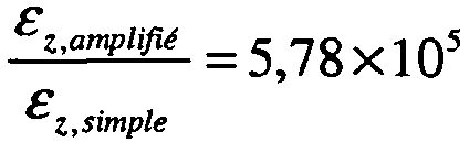
- La taille du cylindre dépend de l'application visée. La limite inférieure de son diamètre dépend, en partie, des pertes et de la biréfringence de la fibre. Il faut également noter que, si l'enroulement de la fibre biréfringente est effectué de telle sorte que l'un de ses deux axes propres subisse préférentiellement la contrainte, par exemple, si cet axe est perpendiculaire à l'axe du cylindre tout le long de l'enroulement, l'écart en fréquence δν1(ε)-δν2(ε) peut être augmenté.
- Les capteurs précédents peuvent être facilement multiplexer comme illustré en
figure 6 . Pour multiplexer plusieurs capteurs i selon l'invention, il est nécessaire d'ajouter au dispositif de lafigure 1 , un laser sonde 20 se propageant dans le même sens que la pompe. Ce laser sonde est soit une source large autour de 1,5µm, soit une source accordable autour de 1,5µm, adaptée à la longueur d'onde de Bragg des miroirs de fond de cavité. Les capteurs peuvent être réalisés selon les modes décrits précédemment. Dans ce cas, chaque capteur i comporte une fibre 10i qui émet deux ondes 1i'et 2i' ayant les fréquences νi1 et νi2. - Le multiplexage permettant de discriminer les signaux provenant des différents capteurs peut être réalisé par différentes techniques. On citera le multiplexage temporel ou le multiplexage spectral.
Claims (6)
- Capteur à fibre optique de mesure d'une grandeur physique comprenant au moins :• une fibre optique (10) de mesure comportant au moins un milieu amplificateur (11) et un réseau de Bragg (12) ;• des moyens de pompage optique (20) du dit milieu amplificateur assurant l'inversion de population dudit milieu ;• la fibre optique (10) est une fibre à maintien de polarisation biréfringente, comportant deux axes propres d'indice de réfraction respectifs ne et no, caractérisé en ce que:• le capteur comporte des moyens d'émission d'une onde optique dite sonde, ladite onde créant par interférence avec elle-même après réflexion sur le réseau de Bragg un réseau de gain dynamique (13) donnant naissance à deux ondes optiques (1', 2') de fréquence optique différente, les deux fréquences optiques dépendant de la grandeur physique ;• le capteur comporte des moyens d'analyse (40) de la différence de fréquence entre les deux ondes optiques.
- Capteur à fibre optique selon la revendication 1, caractérisé en ce que le capteur est un capteur de contraintes, la grandeur physique à mesurer étant une contrainte mécanique appliquée sur la fibre.
- Capteur à fibre optique selon la revendication 2, caractérisé en ce que le capteur est un hydrophone.
- Capteur à fibre optique selon l'une des revendications 2 ou 3 , caractérisé en ce que le capteur comporte une structure sensiblement cylindrique (50) sur laquelle est enroulée la fibre optique de mesure, ledit cylindre étant réalisé dans un matériau ayant un module d'Young le plus faible possible de façon à amplifier la contrainte exercée sur la fibre.
- Capteur à fibre optique selon la revendication 4, caractérisé en ce que le matériau du cylindre est le polymethylsiloxane.
- Réseau de capteurs à fibre optique selon l'une des revendications précédentes, caractérisé en ce que tous les capteurs sont disposés en série sur une même fibre optique et que le réseau comporte un multiplexeur en longueurs d'onde disposé entre ladite fibre et les moyens d'analyse.
Applications Claiming Priority (2)
| Application Number | Priority Date | Filing Date | Title |
|---|---|---|---|
| FR0801482A FR2929000B1 (fr) | 2008-03-18 | 2008-03-18 | Capteur a fibre optique auto-reference et reseau de capteurs associe |
| PCT/EP2009/053100 WO2009115501A1 (fr) | 2008-03-18 | 2009-03-16 | Capteur a fibre optique auto-reference et reseau de capteurs associe |
Publications (2)
| Publication Number | Publication Date |
|---|---|
| EP2255159A1 EP2255159A1 (fr) | 2010-12-01 |
| EP2255159B1 true EP2255159B1 (fr) | 2016-06-29 |
Family
ID=40192874
Family Applications (1)
| Application Number | Title | Priority Date | Filing Date |
|---|---|---|---|
| EP09721635.2A Active EP2255159B1 (fr) | 2008-03-18 | 2009-03-16 | Capteur a fibre optique auto-reference et reseau de capteurs associe |
Country Status (6)
| Country | Link |
|---|---|
| US (1) | US8290316B2 (fr) |
| EP (1) | EP2255159B1 (fr) |
| AU (1) | AU2009226942B2 (fr) |
| DK (1) | DK2255159T3 (fr) |
| FR (1) | FR2929000B1 (fr) |
| WO (1) | WO2009115501A1 (fr) |
Families Citing this family (24)
| Publication number | Priority date | Publication date | Assignee | Title |
|---|---|---|---|---|
| FR2913110B1 (fr) * | 2007-02-28 | 2009-05-22 | Thales Sa | Capteur de grandeurs physiques a fibre optique insensible aux grandeurs statiques |
| FR2929000B1 (fr) * | 2008-03-18 | 2010-04-09 | Thales Sa | Capteur a fibre optique auto-reference et reseau de capteurs associe |
| US8234924B2 (en) * | 2008-07-17 | 2012-08-07 | Optech Ventures, Llc | Apparatus and method for damage location and identification in structures |
| FR2934365B1 (fr) * | 2008-07-25 | 2010-08-13 | Thales Sa | Capteur a fibre optique auto-reference a diffusion brillouin stimulee |
| US9134242B2 (en) * | 2009-04-27 | 2015-09-15 | Ecole Polytechnique Federale De Lausanne (Epfl) | Method and apparatus for retrieval of amplitude and phase of nonlinear electromagnetic waves |
| FR2945348B1 (fr) | 2009-05-07 | 2011-05-13 | Thales Sa | Procede d'identification d'une scene a partir d'images polarisees multi longueurs d'onde |
| EP2646862B1 (fr) * | 2010-12-02 | 2020-09-23 | Ofs Fitel Llc | Capteur courbe de laser à fibre dfb et microphone hétérodyne optique |
| JP5607185B2 (ja) * | 2011-02-14 | 2014-10-15 | 株式会社環境総合テクノス | 自然および人工構造物変状検知装置 |
| WO2012127808A1 (fr) * | 2011-03-22 | 2012-09-27 | パナソニック株式会社 | Microphone optique |
| US8493555B2 (en) * | 2011-04-29 | 2013-07-23 | Corning Incorporated | Distributed Brillouin sensing systems and methods using few-mode sensing optical fiber |
| US8693834B2 (en) * | 2011-08-15 | 2014-04-08 | Corning Incorporated | Few mode optical fibers for mode division multiplexing |
| WO2013027373A1 (fr) * | 2011-08-25 | 2013-02-28 | パナソニック株式会社 | Microphone optique |
| US9083147B2 (en) * | 2011-10-28 | 2015-07-14 | Ofs Fitel, Llc | Distributed feedback (DFB) Brillouin fiber lasers |
| JP5936057B2 (ja) | 2012-08-27 | 2016-06-15 | 国立大学法人 東京大学 | 光ファイバ特性測定装置及び光ファイバ特性測定方法 |
| TWI512273B (zh) * | 2013-01-22 | 2015-12-11 | Univ Nat Kaohsiung Applied Sci | 光纖感測器製造方法及其構造 |
| CN103983289B (zh) * | 2014-05-09 | 2016-06-15 | 天津大学 | 一种基于双偏振光纤激光传感器的拍频信号双路解调装置 |
| CN104180834B (zh) * | 2014-07-29 | 2016-08-24 | 天津大学 | 一种用于双频率声波检测的光纤激光传感系统 |
| US9923634B2 (en) | 2015-09-23 | 2018-03-20 | Fujitsu Limited | Harmonic generation and phase sensitive amplification using a bragg reflection waveguide |
| FR3047076A1 (fr) * | 2016-01-26 | 2017-07-28 | Commissariat Energie Atomique | Dispositif distribue de detection d'une substance |
| US9906870B2 (en) * | 2016-02-15 | 2018-02-27 | Aalap Rajendra SHAH | Apparatuses and methods for sound recording, manipulation, distribution and pressure wave creation through energy transfer between photons and media particles |
| US10495610B2 (en) * | 2017-08-14 | 2019-12-03 | Geoffrey A. Cranch | Fiber optic acoustic emission sensor and apparatus |
| CN113206427B (zh) * | 2021-04-30 | 2022-07-19 | 中国人民解放军国防科技大学 | 一种高重频线偏振飞秒锁模光纤激光器 |
| US11656140B1 (en) | 2022-04-25 | 2023-05-23 | The Government Of The United States Of America, As Represented By The Secretary Of The Navy | Coated fiber optic pressure sensor with improved acceleration response |
| CN114578412B (zh) * | 2022-05-05 | 2022-08-09 | 华中科技大学 | 一种光纤微振动检波测量系统 |
Family Cites Families (16)
| Publication number | Priority date | Publication date | Assignee | Title |
|---|---|---|---|---|
| FR2460582A1 (fr) | 1979-06-29 | 1981-01-23 | Thomson Csf | Hydrophone a fibre optique monomode fonctionnant par effet elasto-optique |
| NO302441B1 (no) * | 1995-03-20 | 1998-03-02 | Optoplan As | Fiberoptisk endepumpet fiber-laser |
| DE19807891A1 (de) | 1998-02-25 | 1999-08-26 | Abb Research Ltd | Faserlaser-Drucksensor |
| CA2644216C (fr) | 1998-12-17 | 2011-02-08 | University Of Southampton | Appareil et procede de protection de dispositifs, notamment des dispositifs a fibres optiques, dans des milieux hostiles |
| US6668105B2 (en) | 2000-07-27 | 2003-12-23 | Systems Planning & Analysis, Inc. | Fiber optic strain sensor |
| EP1197738A1 (fr) * | 2000-10-18 | 2002-04-17 | Abb Research Ltd. | Capteur à fibre anysotrope avec réaction distribuée |
| GB0030289D0 (en) * | 2000-12-12 | 2001-01-24 | Optoplan As | Fibre optic sensor systems |
| US6782205B2 (en) * | 2001-06-25 | 2004-08-24 | Silicon Light Machines | Method and apparatus for dynamic equalization in wavelength division multiplexing |
| EP1359394A1 (fr) * | 2002-04-30 | 2003-11-05 | Abb Research Ltd. | Capteur laser à fibre optique de haute résolution |
| US7245789B2 (en) * | 2002-10-07 | 2007-07-17 | Vascular Imaging Corporation | Systems and methods for minimally-invasive optical-acoustic imaging |
| NO339298B1 (no) * | 2003-10-10 | 2016-11-21 | Optoplan As | Aktiv koherensreduksjon for interferometeravspørring |
| US7483598B2 (en) * | 2004-03-15 | 2009-01-27 | Queen's University At Kingston | Phase shift optical loop spectroscopy |
| US7283216B1 (en) * | 2004-06-22 | 2007-10-16 | Np Photonics, Inc. | Distributed fiber sensor based on spontaneous brilluoin scattering |
| US7206259B2 (en) * | 2004-12-15 | 2007-04-17 | The Hong Kong Polytechnic University | Ultrasound sensor and ultrasound measurement device |
| FR2913110B1 (fr) | 2007-02-28 | 2009-05-22 | Thales Sa | Capteur de grandeurs physiques a fibre optique insensible aux grandeurs statiques |
| FR2929000B1 (fr) * | 2008-03-18 | 2010-04-09 | Thales Sa | Capteur a fibre optique auto-reference et reseau de capteurs associe |
-
2008
- 2008-03-18 FR FR0801482A patent/FR2929000B1/fr active Active
-
2009
- 2009-03-16 WO PCT/EP2009/053100 patent/WO2009115501A1/fr not_active Ceased
- 2009-03-16 EP EP09721635.2A patent/EP2255159B1/fr active Active
- 2009-03-16 AU AU2009226942A patent/AU2009226942B2/en active Active
- 2009-03-16 DK DK09721635.2T patent/DK2255159T3/en active
- 2009-03-16 US US12/933,057 patent/US8290316B2/en not_active Expired - Fee Related
Also Published As
| Publication number | Publication date |
|---|---|
| FR2929000A1 (fr) | 2009-09-25 |
| US20110019179A1 (en) | 2011-01-27 |
| FR2929000B1 (fr) | 2010-04-09 |
| EP2255159A1 (fr) | 2010-12-01 |
| DK2255159T3 (en) | 2016-10-10 |
| AU2009226942A1 (en) | 2009-09-24 |
| AU2009226942B2 (en) | 2014-02-20 |
| US8290316B2 (en) | 2012-10-16 |
| WO2009115501A1 (fr) | 2009-09-24 |
Similar Documents
| Publication | Publication Date | Title |
|---|---|---|
| EP2255159B1 (fr) | Capteur a fibre optique auto-reference et reseau de capteurs associe | |
| EP2307856B1 (fr) | Capteur a fibre optique auto-reference a diffusion brillouin stimulee | |
| EP2126518B1 (fr) | Capteur de grandeurs physiques a fibre optique insensible aux grandeurs statiques | |
| EP3274662B1 (fr) | Capteur a fibre optique distribue d'etat de contrainte | |
| EP3243042B1 (fr) | Capteur a fibre optique | |
| FR2541767A1 (fr) | Hydrophone a fibre optique | |
| EP3071938B1 (fr) | Capteur à fibre optique grande sensibilité | |
| Wu et al. | Long-range temperature sensing based on forward Brillouin scattering in highly nonlinear fiber | |
| Azmi et al. | Sensitivity enhancement in composite cavity fiber laser hydrophone | |
| EP4097423B1 (fr) | Système de mesure d'une pluralité de paramètres physiques en un point de mesure par une fibre optique multimode | |
| Tikhomirov et al. | DFB FL sensor multiplexing noise | |
| Chow et al. | Long distance high performance remote strain sensing with a fiber Fabry-Perot by radio-frequency laser modulation | |
| Sylvestre et al. | Capteur Brillouin réparti à fibre optique à haute résolution et longue portée | |
| Sylvestre et al. | Long-range and high-resolution distributed Brillouin fiber sensors| Capteur Brillouin réparti à fibre optique à haute résolution et longue portée |
Legal Events
| Date | Code | Title | Description |
|---|---|---|---|
| PUAI | Public reference made under article 153(3) epc to a published international application that has entered the european phase |
Free format text: ORIGINAL CODE: 0009012 |
|
| 17P | Request for examination filed |
Effective date: 20100914 |
|
| AK | Designated contracting states |
Kind code of ref document: A1 Designated state(s): AT BE BG CH CY CZ DE DK EE ES FI FR GB GR HR HU IE IS IT LI LT LU LV MC MK MT NL NO PL PT RO SE SI SK TR |
|
| AX | Request for extension of the european patent |
Extension state: AL BA RS |
|
| DAX | Request for extension of the european patent (deleted) | ||
| GRAP | Despatch of communication of intention to grant a patent |
Free format text: ORIGINAL CODE: EPIDOSNIGR1 |
|
| GRAJ | Information related to disapproval of communication of intention to grant by the applicant or resumption of examination proceedings by the epo deleted |
Free format text: ORIGINAL CODE: EPIDOSDIGR1 |
|
| INTG | Intention to grant announced |
Effective date: 20151222 |
|
| GRAP | Despatch of communication of intention to grant a patent |
Free format text: ORIGINAL CODE: EPIDOSNIGR1 |
|
| INTC | Intention to grant announced (deleted) | ||
| INTG | Intention to grant announced |
Effective date: 20160129 |
|
| GRAS | Grant fee paid |
Free format text: ORIGINAL CODE: EPIDOSNIGR3 |
|
| GRAA | (expected) grant |
Free format text: ORIGINAL CODE: 0009210 |
|
| RAP1 | Party data changed (applicant data changed or rights of an application transferred) |
Owner name: THALES |
|
| AK | Designated contracting states |
Kind code of ref document: B1 Designated state(s): AT BE BG CH CY CZ DE DK EE ES FI FR GB GR HR HU IE IS IT LI LT LU LV MC MK MT NL NO PL PT RO SE SI SK TR |
|
| REG | Reference to a national code |
Ref country code: GB Ref legal event code: FG4D Free format text: NOT ENGLISH |
|
| REG | Reference to a national code |
Ref country code: CH Ref legal event code: EP |
|
| REG | Reference to a national code |
Ref country code: AT Ref legal event code: REF Ref document number: 809467 Country of ref document: AT Kind code of ref document: T Effective date: 20160715 |
|
| REG | Reference to a national code |
Ref country code: IE Ref legal event code: FG4D Free format text: LANGUAGE OF EP DOCUMENT: FRENCH |
|
| REG | Reference to a national code |
Ref country code: DE Ref legal event code: R096 Ref document number: 602009039443 Country of ref document: DE |
|
| REG | Reference to a national code |
Ref country code: DK Ref legal event code: T3 Effective date: 20161006 |
|
| REG | Reference to a national code |
Ref country code: SE Ref legal event code: TRGR |
|
| REG | Reference to a national code |
Ref country code: LT Ref legal event code: MG4D |
|
| PG25 | Lapsed in a contracting state [announced via postgrant information from national office to epo] |
Ref country code: LT Free format text: LAPSE BECAUSE OF FAILURE TO SUBMIT A TRANSLATION OF THE DESCRIPTION OR TO PAY THE FEE WITHIN THE PRESCRIBED TIME-LIMIT Effective date: 20160629 Ref country code: FI Free format text: LAPSE BECAUSE OF FAILURE TO SUBMIT A TRANSLATION OF THE DESCRIPTION OR TO PAY THE FEE WITHIN THE PRESCRIBED TIME-LIMIT Effective date: 20160629 Ref country code: NO Free format text: LAPSE BECAUSE OF FAILURE TO SUBMIT A TRANSLATION OF THE DESCRIPTION OR TO PAY THE FEE WITHIN THE PRESCRIBED TIME-LIMIT Effective date: 20160929 |
|
| REG | Reference to a national code |
Ref country code: NL Ref legal event code: MP Effective date: 20160629 |
|
| PG25 | Lapsed in a contracting state [announced via postgrant information from national office to epo] |
Ref country code: HR Free format text: LAPSE BECAUSE OF FAILURE TO SUBMIT A TRANSLATION OF THE DESCRIPTION OR TO PAY THE FEE WITHIN THE PRESCRIBED TIME-LIMIT Effective date: 20160629 Ref country code: LV Free format text: LAPSE BECAUSE OF FAILURE TO SUBMIT A TRANSLATION OF THE DESCRIPTION OR TO PAY THE FEE WITHIN THE PRESCRIBED TIME-LIMIT Effective date: 20160629 Ref country code: GR Free format text: LAPSE BECAUSE OF FAILURE TO SUBMIT A TRANSLATION OF THE DESCRIPTION OR TO PAY THE FEE WITHIN THE PRESCRIBED TIME-LIMIT Effective date: 20160930 Ref country code: NL Free format text: LAPSE BECAUSE OF FAILURE TO SUBMIT A TRANSLATION OF THE DESCRIPTION OR TO PAY THE FEE WITHIN THE PRESCRIBED TIME-LIMIT Effective date: 20160629 |
|
| REG | Reference to a national code |
Ref country code: AT Ref legal event code: MK05 Ref document number: 809467 Country of ref document: AT Kind code of ref document: T Effective date: 20160629 |
|
| PG25 | Lapsed in a contracting state [announced via postgrant information from national office to epo] |
Ref country code: EE Free format text: LAPSE BECAUSE OF FAILURE TO SUBMIT A TRANSLATION OF THE DESCRIPTION OR TO PAY THE FEE WITHIN THE PRESCRIBED TIME-LIMIT Effective date: 20160629 Ref country code: SK Free format text: LAPSE BECAUSE OF FAILURE TO SUBMIT A TRANSLATION OF THE DESCRIPTION OR TO PAY THE FEE WITHIN THE PRESCRIBED TIME-LIMIT Effective date: 20160629 Ref country code: IT Free format text: LAPSE BECAUSE OF FAILURE TO SUBMIT A TRANSLATION OF THE DESCRIPTION OR TO PAY THE FEE WITHIN THE PRESCRIBED TIME-LIMIT Effective date: 20160629 Ref country code: RO Free format text: LAPSE BECAUSE OF FAILURE TO SUBMIT A TRANSLATION OF THE DESCRIPTION OR TO PAY THE FEE WITHIN THE PRESCRIBED TIME-LIMIT Effective date: 20160629 Ref country code: IS Free format text: LAPSE BECAUSE OF FAILURE TO SUBMIT A TRANSLATION OF THE DESCRIPTION OR TO PAY THE FEE WITHIN THE PRESCRIBED TIME-LIMIT Effective date: 20161029 Ref country code: CZ Free format text: LAPSE BECAUSE OF FAILURE TO SUBMIT A TRANSLATION OF THE DESCRIPTION OR TO PAY THE FEE WITHIN THE PRESCRIBED TIME-LIMIT Effective date: 20160629 |
|
| REG | Reference to a national code |
Ref country code: FR Ref legal event code: PLFP Year of fee payment: 9 |
|
| PG25 | Lapsed in a contracting state [announced via postgrant information from national office to epo] |
Ref country code: PL Free format text: LAPSE BECAUSE OF FAILURE TO SUBMIT A TRANSLATION OF THE DESCRIPTION OR TO PAY THE FEE WITHIN THE PRESCRIBED TIME-LIMIT Effective date: 20160629 Ref country code: AT Free format text: LAPSE BECAUSE OF FAILURE TO SUBMIT A TRANSLATION OF THE DESCRIPTION OR TO PAY THE FEE WITHIN THE PRESCRIBED TIME-LIMIT Effective date: 20160629 Ref country code: ES Free format text: LAPSE BECAUSE OF FAILURE TO SUBMIT A TRANSLATION OF THE DESCRIPTION OR TO PAY THE FEE WITHIN THE PRESCRIBED TIME-LIMIT Effective date: 20160629 Ref country code: PT Free format text: LAPSE BECAUSE OF FAILURE TO SUBMIT A TRANSLATION OF THE DESCRIPTION OR TO PAY THE FEE WITHIN THE PRESCRIBED TIME-LIMIT Effective date: 20161031 |
|
| REG | Reference to a national code |
Ref country code: DE Ref legal event code: R097 Ref document number: 602009039443 Country of ref document: DE |
|
| PGFP | Annual fee paid to national office [announced via postgrant information from national office to epo] |
Ref country code: SE Payment date: 20170313 Year of fee payment: 9 |
|
| PLBE | No opposition filed within time limit |
Free format text: ORIGINAL CODE: 0009261 |
|
| STAA | Information on the status of an ep patent application or granted ep patent |
Free format text: STATUS: NO OPPOSITION FILED WITHIN TIME LIMIT |
|
| PGFP | Annual fee paid to national office [announced via postgrant information from national office to epo] |
Ref country code: DK Payment date: 20170310 Year of fee payment: 9 Ref country code: GB Payment date: 20170303 Year of fee payment: 9 |
|
| 26N | No opposition filed |
Effective date: 20170330 |
|
| PG25 | Lapsed in a contracting state [announced via postgrant information from national office to epo] |
Ref country code: SI Free format text: LAPSE BECAUSE OF FAILURE TO SUBMIT A TRANSLATION OF THE DESCRIPTION OR TO PAY THE FEE WITHIN THE PRESCRIBED TIME-LIMIT Effective date: 20160629 Ref country code: BG Free format text: LAPSE BECAUSE OF FAILURE TO SUBMIT A TRANSLATION OF THE DESCRIPTION OR TO PAY THE FEE WITHIN THE PRESCRIBED TIME-LIMIT Effective date: 20160929 |
|
| REG | Reference to a national code |
Ref country code: CH Ref legal event code: PL |
|
| PG25 | Lapsed in a contracting state [announced via postgrant information from national office to epo] |
Ref country code: MC Free format text: LAPSE BECAUSE OF FAILURE TO SUBMIT A TRANSLATION OF THE DESCRIPTION OR TO PAY THE FEE WITHIN THE PRESCRIBED TIME-LIMIT Effective date: 20160629 |
|
| REG | Reference to a national code |
Ref country code: IE Ref legal event code: MM4A |
|
| PG25 | Lapsed in a contracting state [announced via postgrant information from national office to epo] |
Ref country code: LU Free format text: LAPSE BECAUSE OF NON-PAYMENT OF DUE FEES Effective date: 20170316 |
|
| REG | Reference to a national code |
Ref country code: FR Ref legal event code: PLFP Year of fee payment: 10 |
|
| PG25 | Lapsed in a contracting state [announced via postgrant information from national office to epo] |
Ref country code: IE Free format text: LAPSE BECAUSE OF NON-PAYMENT OF DUE FEES Effective date: 20170316 Ref country code: LI Free format text: LAPSE BECAUSE OF NON-PAYMENT OF DUE FEES Effective date: 20170331 Ref country code: CH Free format text: LAPSE BECAUSE OF NON-PAYMENT OF DUE FEES Effective date: 20170331 |
|
| REG | Reference to a national code |
Ref country code: BE Ref legal event code: MM Effective date: 20170331 |
|
| PG25 | Lapsed in a contracting state [announced via postgrant information from national office to epo] |
Ref country code: BE Free format text: LAPSE BECAUSE OF NON-PAYMENT OF DUE FEES Effective date: 20170331 |
|
| PG25 | Lapsed in a contracting state [announced via postgrant information from national office to epo] |
Ref country code: MT Free format text: LAPSE BECAUSE OF FAILURE TO SUBMIT A TRANSLATION OF THE DESCRIPTION OR TO PAY THE FEE WITHIN THE PRESCRIBED TIME-LIMIT Effective date: 20160629 |
|
| REG | Reference to a national code |
Ref country code: DK Ref legal event code: EBP Effective date: 20180331 |
|
| PG25 | Lapsed in a contracting state [announced via postgrant information from national office to epo] |
Ref country code: SE Free format text: LAPSE BECAUSE OF NON-PAYMENT OF DUE FEES Effective date: 20180317 |
|
| GBPC | Gb: european patent ceased through non-payment of renewal fee |
Effective date: 20180316 |
|
| PG25 | Lapsed in a contracting state [announced via postgrant information from national office to epo] |
Ref country code: GB Free format text: LAPSE BECAUSE OF NON-PAYMENT OF DUE FEES Effective date: 20180316 |
|
| PGFP | Annual fee paid to national office [announced via postgrant information from national office to epo] |
Ref country code: BE Payment date: 20190426 Year of fee payment: 13 |
|
| PG25 | Lapsed in a contracting state [announced via postgrant information from national office to epo] |
Ref country code: DK Free format text: LAPSE BECAUSE OF NON-PAYMENT OF DUE FEES Effective date: 20180331 |
|
| PG25 | Lapsed in a contracting state [announced via postgrant information from national office to epo] |
Ref country code: HU Free format text: LAPSE BECAUSE OF FAILURE TO SUBMIT A TRANSLATION OF THE DESCRIPTION OR TO PAY THE FEE WITHIN THE PRESCRIBED TIME-LIMIT; INVALID AB INITIO Effective date: 20090316 |
|
| PG25 | Lapsed in a contracting state [announced via postgrant information from national office to epo] |
Ref country code: CY Free format text: LAPSE BECAUSE OF NON-PAYMENT OF DUE FEES Effective date: 20160629 |
|
| PG25 | Lapsed in a contracting state [announced via postgrant information from national office to epo] |
Ref country code: MK Free format text: LAPSE BECAUSE OF FAILURE TO SUBMIT A TRANSLATION OF THE DESCRIPTION OR TO PAY THE FEE WITHIN THE PRESCRIBED TIME-LIMIT Effective date: 20160629 |
|
| PG25 | Lapsed in a contracting state [announced via postgrant information from national office to epo] |
Ref country code: TR Free format text: LAPSE BECAUSE OF FAILURE TO SUBMIT A TRANSLATION OF THE DESCRIPTION OR TO PAY THE FEE WITHIN THE PRESCRIBED TIME-LIMIT Effective date: 20160629 |
|
| REG | Reference to a national code |
Ref country code: DE Ref legal event code: R119 Ref document number: 602009039443 Country of ref document: DE |
|
| PG25 | Lapsed in a contracting state [announced via postgrant information from national office to epo] |
Ref country code: DE Free format text: LAPSE BECAUSE OF NON-PAYMENT OF DUE FEES Effective date: 20201001 |
|
| P01 | Opt-out of the competence of the unified patent court (upc) registered |
Effective date: 20230606 |
|
| PGFP | Annual fee paid to national office [announced via postgrant information from national office to epo] |
Ref country code: FR Payment date: 20260223 Year of fee payment: 18 |