EP2255371B1 - Permanentmagnet-lichtbogenlöscheinrichtung für lasttrennschalter - Google Patents
Permanentmagnet-lichtbogenlöscheinrichtung für lasttrennschalter Download PDFInfo
- Publication number
- EP2255371B1 EP2255371B1 EP09721626.1A EP09721626A EP2255371B1 EP 2255371 B1 EP2255371 B1 EP 2255371B1 EP 09721626 A EP09721626 A EP 09721626A EP 2255371 B1 EP2255371 B1 EP 2255371B1
- Authority
- EP
- European Patent Office
- Prior art keywords
- permanent magnet
- magnet
- quenching device
- arc
- extinguishing device
- Prior art date
- Legal status (The legal status is an assumption and is not a legal conclusion. Google has not performed a legal analysis and makes no representation as to the accuracy of the status listed.)
- Active
Links
Images

Classifications
-
- H—ELECTRICITY
- H01—ELECTRIC ELEMENTS
- H01H—ELECTRIC SWITCHES; RELAYS; SELECTORS; EMERGENCY PROTECTIVE DEVICES
- H01H33/00—High-tension or heavy-current switches with arc-extinguishing or arc-preventing means
- H01H33/02—Details
- H01H33/04—Means for extinguishing or preventing arc between current-carrying parts
- H01H33/18—Means for extinguishing or preventing arc between current-carrying parts using blow-out magnet
- H01H33/187—Means for extinguishing or preventing arc between current-carrying parts using blow-out magnet comprising a hollow annular arc runner and a central contact between which a radially drawn arc rotates
-
- H—ELECTRICITY
- H01—ELECTRIC ELEMENTS
- H01H—ELECTRIC SWITCHES; RELAYS; SELECTORS; EMERGENCY PROTECTIVE DEVICES
- H01H33/00—High-tension or heavy-current switches with arc-extinguishing or arc-preventing means
- H01H33/02—Details
- H01H33/04—Means for extinguishing or preventing arc between current-carrying parts
- H01H33/12—Auxiliary contacts on to which the arc is transferred from the main contacts
- H01H33/121—Load break switches
-
- H—ELECTRICITY
- H01—ELECTRIC ELEMENTS
- H01H—ELECTRIC SWITCHES; RELAYS; SELECTORS; EMERGENCY PROTECTIVE DEVICES
- H01H33/00—High-tension or heavy-current switches with arc-extinguishing or arc-preventing means
- H01H33/02—Details
- H01H33/04—Means for extinguishing or preventing arc between current-carrying parts
- H01H33/18—Means for extinguishing or preventing arc between current-carrying parts using blow-out magnet
- H01H33/182—Means for extinguishing or preventing arc between current-carrying parts using blow-out magnet using permanent magnets
Definitions
- An Indian EP 0296 915 B1 described load-disconnect rotary switch has on the fixed contacts in each case a permanent magnet extinguishing device, which shifts the arc root of a resulting arc when opening the contact system in a shadow position on the fixed contact arrangement, so that a re-ignition of the arc is prevented after a current zero crossing.
- the permanent magnet extinguishing device comprises a ring-shaped permanent magnet, which is supported on the side facing the moving contact on an electrically conductive, via a headband galvanically connected to the mounting tabs and thus with the fixed contact ring element.
- a headband galvanically connected to the mounting tabs and thus with the fixed contact ring element.
- At the free end and side surfaces of the permanent magnet is through an iron yoke sleeve and the ring element releasing iron back plate shielded, which simultaneously serve to amplify the magnetic field.
- a cover ring and a - the ring element not covering - cover part are provided, each made of plastic.
- the mutual positioning and fixing of the individual components via the cover and the cover part which can be latched on special locking means with the brackets and mounting straps.
- An arc resulting from the opening of a contact system, the root of which rotates along the path of the arc, extends to the permanent magnet extinguishing system, so that the arc extinguishes at the following current zero crossing.
- the known permanent magnet extinguishing device is disadvantageous in that the metallic components are only incompletely isolated by the cover ring and the cover part made of plastic and not exactly positioned to each other and thus a controlled rotation of the arc root and a rapid extinction of the arc is not guaranteed. In addition, the installation effort is high.
- the invention has for its object to provide a permanent magnet extinguishing device of the type mentioned above, which can be manufactured with little effort and ensures a quick and safe extinguishing an arc.
- the essence of the invention is that the free outer surfaces of the individual metallic components with a one-piece Isolierstoffummantelung are covered, but the arc career remains free. Apart from the arc running all metal components of the extinguishing device are thus isolated from a resulting arc when disconnecting the switch contacts, which is thus deleted quickly and safely. A deviation of the arc root from the exact defined by the Isolierstoffummantelung arc career to other metallic components is not possible.
- the gap-free insulating coating also ensures reliable corrosion protection.
- the application of the Isolierstoffummantelung is preferably carried out in an injection mold in which the components of the extinguishing device are positioned in a position identical to each other during each injection process before applying the insulating material.
- the Isolierstoffummantelung consists of a thermoplastic, plastic.
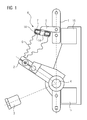
- Fig. 1 shows a fixed contact 1 and a moving contact 2, which are each connected to a plastic support 15, and a grounding contact 3 of a circuit breaker for a gas-insulated switchgear.
- the pivotable moving contact 2 designed as a double knife contact in the present embodiment is fastened to a switching shaft 4 and can thus be connected in a simple manner either to the fixed contact 1 or to the grounding contact 3 by actuating the switching shaft.
- a permanent magnet extinguishing device 6 is attached by means of a conductive fastener 5 connected thereto.
- position corresponds to a disconnected position according to a triggered by the switching shaft 4 switching operation in which the moving contact 2 has been separated from the fixed contact 1.
- a formed in this separation process between the fixed contact 1 and the moving contact 2 arc G is deleted by the fixed contact 1 associated permanent magnet extinguishing device 6 by the arc G on the spaced from the path of movement of the moving contact 2 arranged permanent magnet extinguishing device 6 and Thus, a re-ignition of the arc is prevented after a current zero crossing.
- the arc G is rotated by the magnetic field of a permanent magnet 7 arranged in the permanent magnet extinguishing device into a rotational movement along a ring element 9 which is electrically connected via a retaining clip 8 to the fastening means 5 and thus to the fixed contact 1 added.
- the annular permanent magnet 7 is at the fixed contact 1 facing upper end face and the side surface with a EisenschreibInstitut briefly devisInstituttopf 11, in the bottom of which an inner diameter of the permanent magnet corresponding opening, and at the moving contact 2 facing lower end face, but at a distance from Outer edge of the permanent magnet 7, with an annular iron return plate 12 in direct contact.
- the permanent magnet 7 is supported on the ring element 9. Between the ring element 9 and the iron return plate 12, a narrow annular gap 13 (FIG. Fig. 3 ) remain.
- An important advantage of the outward - except for the arc runway 10 - complete sheathing of the permanent magnet extinguishing device 6 with an insulating material is that all metallic components of the extinguishing system with respect to the arc runway 10 and on this rotating base of the arc G are isolated. By the only on the arc career 10 limited, controlled rotation of the arc ensures its fast and safe erasure.
- the production of the permanent magnet extinguishing system 6 is effected by an accurate and exactly repeatable, mutually positionally correct fixing of the individual metallic components in an injection mold and subsequent encapsulation with the insulating material.
- the components are therefore in the use state of the permanent magnet extinguishing device in the predetermined, mutually immovable position.
- the installation effort and the - also due to a reduced number of components reduced - cost can be reduced compared to the effort required for the production of conventional permanent magnet extinguishing systems. Due to the gap-free, only the arc running surface exposed encapsulation of the permanent magnet extinguishing device caused by external effects corrosion phenomena are substantially excluded.
Landscapes
- Arc-Extinguishing Devices That Are Switches (AREA)
- Breakers (AREA)
Description
- Die Erfindung betrifft eine Permanentmagnet-Löscheinrichtung zum Löschen von Lichtbögen im Kontaktsystem von Lasttrennschaltern in gasisolierten Schaltanlagen, die einen mit Eisenrückschlussmitteln versehenen Permanentmagneten, ein den Permanentmagnet am Außenrand abstützendes Ringelement mit einer dem beim Öffnen eines Kontaktsystems entstehenden Lichtbogen zugewandten Lichtbogenlaufbahn, die über Haltebügel galvanisch an einen Festkontakt des Kontaktsystems anschließbar ist, sowie eine isolierende Schutzabdeckung umfasst.
- Ein in der
EP 0296 915 B1 beschriebener Lasttrenndrehschalter weist an den Festkontakten jeweils eine Permanentmagnet-Löscheinrichtung auf, die den Lichtbogenfußpunkt eines beim Öffnen des Kontaktsystems entstehenden Lichtbogens in eine Schattenlage an der Festkontaktanordnung verschiebt, so dass eine Neuzündung des Lichtbogens nach einem Stromnulldurchgang verhindert wird. - Bei einem aus der
WO 2007/068693 A1 bekannten Lasttrennschalter ist mit Hilfe von Befestigungslaschen jeweils außen an den Festkontakten eine Permanentmagnet-Löscheinrichtung angebracht. Die Permanentmagnet-Löscheinrichtung umfasst einen ringförmig ausgebildeten Permanentmagneten, der auf der zum Bewegkontakt weisenden Stirnseite auf einem elektrisch leitenden, über einen Haltebügel galvanisch mit den Befestigungslaschen und damit mit dem Festkontakt verbundenen Ringelement abgestützt ist. An den freien Stirn- und Seitenflächen ist der Permanentmagnet durch eine Eisenrückschlusshülse und eine das Ringelement frei lassende Eisenrückschlussplatte abgeschirmt, die gleichzeitig zur Verstärkung des Magnetfeldes dienen. Als isolierende Schutzabdeckung für die Permanentmagnet-Löschvorrichtung sind ein Abdeckring und ein - das Ringelement nicht abdeckendes - Deckelteil vorgesehen, die jeweils aus Kunststoff bestehen. Die gegenseitige Positionierung und Fixierung der einzelnen Bauteile erfolgt über den Abdeckring und das Deckelteil, die über spezielle Rastmittel mit den Haltebügeln und Befestigungslaschen verrastbar sind. Ein beim Öffnen eines Kontaktsystems entstehender Lichtbogen, dessen Fußpunkt entlang der Lichtbogenlaufbahn rotiert, erstreckt sich zu dem Permanentmagnet-Löschsystem, so dass der Lichtbogen beim folgenden Stromnulldurchgang erlischt. - Die bekannte Permanentmagnet-Löscheinrichtung ist insofern nachteilig, als die metallischen Bauteile durch den Abdeckring und das Deckelteil aus Kunststoff nur unvollständig isoliert und nicht exakt zueinander positioniert sind und somit eine kontrollierte Rotation des Lichtbogenfußpunktes und eine schnelle Löschung des Lichtbogens nicht gewährleistet ist. Zudem ist der Montageaufwand hoch.
- Der Erfindung liegt die Aufgabe zugrunde, eine Permanentmagnet-Löscheinrichtung der eingangs erwähnten Art anzugeben, die mit geringem Aufwand gefertigt werden kann und ein schnelles und sicheres Löschen eines Lichtbogens gewährleistet.
- Erfindungsgemäß wird die Aufgabe mit einer gemäß den Merkmalen des Patentanspruchs 1 ausgebildeten Permanentmagnet-Löscheinrichtung gelöst. Zweckmäßige Ausgestaltungen der Erfindung sind Gegenstand der Unteransprüche.
- Der Kern der Erfindung besteht darin, dass die freien Außenflächen der einzelnen metallischen Bauteile mit einer einstückigen Isolierstoffummantelung abgedeckt sind, jedoch die Lichtbogenlaufbahn frei bleibt. Abgesehen von der Lichtbogenlaufbahn sind somit alle metallischen Bauteile der Löscheinrichtung gegenüber einem beim Trennen der Schalterkontakte entstehenden Lichtbogen isoliert, der somit schnell und sicher gelöscht wird. Ein Abweichen des Lichtbogenfußpunktes von der durch die Isolierstoffummantelung genau definierten Lichtbogenlaufbahn auf andere metallische Bauteile ist nicht möglich. Durch die Isolierstoffummantelung sind die einzelnen Bauteile der Permanentmagnet-Löscheinrichtung in ihrer vorgegebenen Lage formschlüssig und somit exakt und sicher zueinander angeordnet. Die spaltfrei aufgebrachte Isolierstoffummantelung sorgt zudem für einen sicheren Korrosionsschutz. Das Aufbringen der Isolierstoffummantelung erfolgt vorzugsweise in einer Spritzgussform, in der die Bauteile der Löscheinrichtung vor dem Aufbringen des Isolierstoffs in einer bei jedem Spritzvorgang identischen Lage zueinander positioniert sind.
- In Ausgestaltung der Erfindung besteht die Isolierstoffummantelung aus einem thermoplastischen, Kunststoff.
- Ein Ausführungsbeispiel der Erfindung wird anhand der Zeichnung näher erläutert. Es zeigen:
- Fig. 1
- eine Seitenansicht einer aus einem Festkontakt mit einer teilweise im Schnitt dargestellten Permanentmagnet-Löscheinrichtung, einem Bewegungskontakt und einem Erdungskontakt bestehenden Kontaktanordnung eines Lasttrennschalters;
- Fig. 2
- eine Unteransicht der Permanentmagnet-Löscheinrichtung; und
- Fig. 3
- einen Schnitt längs der Linie CC in
Fig. 2 ; -
Fig. 1 zeigt einen Festkontakt 1 und einen Bewegkontakt 2, die jeweils an einen Kunststoffstützer 15 angeschlossen sind, sowie einen Erdungskontakt 3 eines Lasttrennschalters für eine gasisolierte Schaltanlage. Der in der vorliegenden Ausführungsform als Doppelmesserkontakt ausgebildete schwenkbare Bewegkontakt 2 ist an einer Schaltwelle 4 befestigt und kann somit durch Betätigung der Schaltwelle auf einfache Weise entweder mit dem Festkontakt 1 oder mit dem Erdungskontakt 3 verbunden werden. An dem Festkontakt 1 ist mittels eines mit diesem leitend verbundenen Befestigungsmittels 5 eine Permanentmagnet-Löscheinrichtung 6 angebracht. Die inFig. 1 dargestellte Position entspricht einer Trennstellung nach einem von der Schaltwelle 4 ausgelösten Schaltvorgang, bei dem der Bewegkontakt 2 von dem Festkontakt 1 getrennt wurde. Ein bei diesem Trennvorgang zwischen dem Festkontakt 1 und dem Bewegkontakt 2 gebildeter Lichtbogen G wird durch die mit dem Festkontakt 1 verbundene Permanentmagnet-Löscheinrichtung 6 gelöscht, indem der Lichtbogen G auf die im Abstand von der Bewegungsbahn des Bewegkontaktes 2 angeordnete Permanentmagnet-Löscheinrichtung 6 übertritt und somit eine Neuzündung des Lichtbogens nach einem Stromnulldurchgang verhindert wird. Nach dem Übertreten des Lichtbogens auf die Permanentmagnet-Löscheinrichtung 6 wird der Lichtbogen G durch das Magnetfeld eines in der Permanentmagnet-Löscheinrichtung angeordneten Permanentmagneten 7 in eine Rotationsbewegung entlang eines über Haltebügel 8 mit dem Befestigungsmittel 5 und damit mit dem Festkontakt 1 elektrisch leitend verbundenen Ringelements 9 versetzt. Durch die Rotation des Lichtbogens G auf der kreisförmigen Lichtbogenlaufbahn 10 des Ringelements 9 wird ein lokaler Abbrand an der Permanentmagnet-Löscheinrichtung 6 im Wesentlichen verhindert. Aus der inFig. 2 wiedergegebenen Unteransicht der Permanentmagnet-Löscheinrichtung 6 ist die Lichtbogenlaufbahn 10 gut erkennbar. - Wie
Fig. 3 zeigt, ist der ringförmige Permanentmagnet 7 an der zum Festkontakt 1 weisenden oberen Stirnfläche und der Seitenfläche mit einem Eisenrückschlusstopf 11, in dessen Boden sich eine dem Innendurchmesser des Permanentmagneten entsprechende Öffnung befindet, und an der zum Bewegkontakt 2 weisenden unteren Stirnfläche, jedoch im Abstand vom Außenrand des Permanentmagneten 7, mit einer ringförmigen Eisenrückschlussplatte 12 in unmittelbarem Kontakt. An der äußeren freibleibenden Ringfläche seiner unteren Stirnseite stützt sich der Permanentmagnet 7 an dem Ringelement 9 ab. Zwischen dem Ringelement 9 und der Eisenrückschlussplatte 12 kann ein schmaler Ringspalt 13 (Fig. 3 ) verbleiben. - Abgesehen von der frei bleibenden Lichtbogenlaufbahn 10 des Ringelements 9 und dem aus zwei am Festkontakt 1 gehaltenen Befestigungslaschen bestehenden Befestigungsmittel 5 sind alle zuvor erwähnten Bauteile in zusammengesetztem Zustand der Bauteile der Permanentmagnet-Löscheinrichtung 6 in eine einstückige (zusammenhängende) Isolierstoffummantelung 14 eingebettet, in der die Bauteile formschlüssig gehalten und zueinander fixiert sind und die nach außen freien Flächen mit Kunststoff abgedeckt sind. Als Isolierstoff wird vorzugsweise ein thermoplastisches Material eingesetzt. Das thermoplastische Material lässt sich auch bei einer komplizierten Geometrie leicht verarbeiten und ist zudem kostengünstig. Ein wichtiger Vorteil der nach außen - bis auf die Lichtbogenlaufbahn 10 - vollständigen Ummantelung der Permanentmagnet-Löscheinrichtung 6 mit einem Isolierstoff liegt darin, dass alle metallischen Bauteile des Löschsystems gegenüber der Lichtbogenlaufbahn 10 und dem auf dieser rotierenden Fußpunkt des Lichtbogens G isoliert sind. Durch die nur auf die Lichtbogenlaufbahn 10 begrenzte, kontrollierte Rotation des Lichtbogens ist dessen schnelle und sichere Löschung gewährleistet.
- Die Herstellung des Permanentmagnet-Löschsystems 6 erfolgt durch eine genaue und exakt wiederholbare, zueinander lagerichtige Fixierung der einzelnen metallischen Bauteile in einer Spritzgussform und anschließendes Umspritzen mit dem Isolierstoff. Die Bauteile befinden sich daher im Gebrauchszustand der Permanentmagnet-Löscheinrichtung in der vorgegebenen, zueinander unverrückbaren Position. Der Montageaufwand und der - auch aufgrund einer verringerten Bauteilzahl verminderte - Kostenaufwand können gegenüber dem für die Herstellung herkömmlicher Permanentmagnet-Löschsysteme erforderlichen Aufwand reduziert werden. Aufgrund der spaltfreien, nur die Lichtbogenlauffläche freilassenden Umspritzung der Permanentmagnet-Löscheinrichtung sind durch äußere Einwirkungen hervorgerufene Korrosionserscheinungen im Wesentlichen ausgeschlossen.
Claims (5)
- Permanentmagnet-Löscheinrichtung zum Löschen von Lichtbögen im Kontaktsystem von Lasttrennschaltern in gasisolierten Schaltanlagen, die einen mit Eisenrückschlussmitteln (11, 12) versehenen Permanentmagneten (7), ein den Permanentmagnet (7) am Außenrand abstützendes Ringelement (9) mit einer dem beim Öffnen des aus Fest- und Bewegkontakten (1, 2) bestehenden Kontaktsystems entstehenden Lichtbogen (G) zugewandten Lichtbogenlaufbahn (10), die über Haltebügel (8) galvanisch an einen Festkontakt (1) des Kontaktsystems anschließbar ist, sowie eine isolierende Schutzabdeckung umfasst, dadurch gekennzeichnet, dass die Schutzabdeckung als einstückige Isolierstoffummantelung (14) ausgebildet ist, die - abgesehen von der Lichtbogenlaufbahn (10) - alle freien Außenflächen der Permanentmagnet-Löscheinrichtung (6) spaltfrei abdeckt und deren einzelne Bauteile in ihrer vorgegebenen Lage exakt und dauerhaft formschlüssig fixiert.
- Permanentmagnet-Löscheinrichtung nach Anspruch 1, dadurch gekennzeichnet, dass die Eisenrückschlussmittel einen Eisenrückschlusstopf (11) zur formgenauen Aufnahme und eine Eisenrückschlussplatte (12) zur Abdeckung des Permanentmagneten (7) umfassen und die Einrückschlussplatte (12) ganz oder nahe an das im Randbereich des Permanentmagneten (7) umlaufende Ringelement (9) reicht.
- Permanentmagnet-Löscheinrichtung nach Anspruch 1 oder 2, dadurch gekennzeichnet, dass der Permanentmagnet (7) als Ringmagnet ausgebildet ist und die Eisenrückschlussplatte (12) und der Eisenrückschlusstopf (11) mit dessen Innendurchmesser übereinstimmende Öffnungen aufweisen, wobei die so gebildete zylindrische Innenfläche bis an die Haltebügel (8) von der Isolierstoffummantelung (14) abgedeckt ist.
- Permanentmagnet-Löscheinrichtung nach Anspruch 1, dadurch gekennzeichnet, dass die Isolierstoffummantelung (14) aus einem thermoplastischen Material besteht.
- Permanentmagnet-Löscheinrichtung nach Anspruch 1, dadurch gekennzeichnet, dass die Isolierstoffummantelung (14) eine in einer Spritzgussform, in der die einzelnen Bauteile der Permanentmagnet-Löscheinrichtung (6) lagegenau zueinander positioniert sind, erzeugte Spritzgussummantelung ist.
Applications Claiming Priority (2)
| Application Number | Priority Date | Filing Date | Title |
|---|---|---|---|
| DE200810015463 DE102008015463B3 (de) | 2008-03-18 | 2008-03-18 | Permanentmagnet-Löscheinrichtung für Lasttrennschalter |
| PCT/EP2009/052835 WO2009115439A1 (de) | 2008-03-18 | 2009-03-11 | Permanentmagnet-löscheinrichtung für lasttrennschalter |
Publications (2)
| Publication Number | Publication Date |
|---|---|
| EP2255371A1 EP2255371A1 (de) | 2010-12-01 |
| EP2255371B1 true EP2255371B1 (de) | 2015-09-16 |
Family
ID=40599987
Family Applications (1)
| Application Number | Title | Priority Date | Filing Date |
|---|---|---|---|
| EP09721626.1A Active EP2255371B1 (de) | 2008-03-18 | 2009-03-11 | Permanentmagnet-lichtbogenlöscheinrichtung für lasttrennschalter |
Country Status (5)
| Country | Link |
|---|---|
| EP (1) | EP2255371B1 (de) |
| CN (1) | CN101978452B (de) |
| DE (1) | DE102008015463B3 (de) |
| ES (1) | ES2549180T3 (de) |
| WO (1) | WO2009115439A1 (de) |
Families Citing this family (6)
| Publication number | Priority date | Publication date | Assignee | Title |
|---|---|---|---|---|
| CN102522252A (zh) * | 2011-12-19 | 2012-06-27 | 中国西电电气股份有限公司 | 一种非sf6气体绝缘金属封闭隔离开关的断口结构 |
| GB201810176D0 (en) * | 2018-06-21 | 2018-08-08 | Secheron Hasler Uk Ltd | A switch for closing a circuit |
| GB201810180D0 (en) * | 2018-06-21 | 2018-08-08 | Secheron Hasler Uk Ltd | A switch for closing a circuit |
| FR3094836B1 (fr) * | 2019-04-02 | 2021-07-09 | Pommier | Dispositif de coupure d’arc |
| CN110911192A (zh) * | 2019-12-18 | 2020-03-24 | 柏仕海 | 一种基于伯努利原理的电力分级灭弧装置 |
| CN111048370B (zh) * | 2019-12-28 | 2021-09-24 | 常熟市通润开关厂有限公司 | 一种断路器用高分段灭弧室 |
Family Cites Families (7)
| Publication number | Priority date | Publication date | Assignee | Title |
|---|---|---|---|---|
| GB2119573B (en) * | 1982-04-17 | 1985-09-04 | Northern Eng Ind | Electric arc interrupter |
| EP0125553B1 (de) * | 1983-05-09 | 1988-09-14 | Mitsubishi Denki Kabushiki Kaisha | Schalter des spiralförmigen Lichtbogentyps |
| EP0483121B1 (de) * | 1986-06-06 | 1994-09-07 | Mitsubishi Denki Kabushiki Kaisha | Schaltvorrichtung |
| FR2618251B1 (fr) * | 1987-06-25 | 1989-11-17 | Merlin Gerin | Interrupteur rotatif a piste courbe de migration d'une racine d'arc. |
| FR2682808B1 (fr) * | 1991-10-17 | 1997-01-24 | Merlin Gerin | Disjoncteur hybride a bobine de soufflage axial. |
| DE4243249A1 (de) * | 1992-12-19 | 1994-06-23 | Abb Patent Gmbh | Elektrischer Schalter |
| DE102005060633A1 (de) * | 2005-12-13 | 2007-06-14 | Siemens Ag | Lasttrennschalter für eine gekapselte Schaltanlage |
-
2008
- 2008-03-18 DE DE200810015463 patent/DE102008015463B3/de not_active Expired - Fee Related
-
2009
- 2009-03-11 EP EP09721626.1A patent/EP2255371B1/de active Active
- 2009-03-11 WO PCT/EP2009/052835 patent/WO2009115439A1/de not_active Ceased
- 2009-03-11 CN CN200980109877.1A patent/CN101978452B/zh active Active
- 2009-03-11 ES ES09721626.1T patent/ES2549180T3/es active Active
Also Published As
| Publication number | Publication date |
|---|---|
| EP2255371A1 (de) | 2010-12-01 |
| CN101978452B (zh) | 2013-10-23 |
| DE102008015463B3 (de) | 2009-09-17 |
| CN101978452A (zh) | 2011-02-16 |
| ES2549180T3 (es) | 2015-10-23 |
| HK1149845A1 (en) | 2011-10-14 |
| WO2009115439A1 (de) | 2009-09-24 |
Similar Documents
| Publication | Publication Date | Title |
|---|---|---|
| EP2255371B1 (de) | Permanentmagnet-lichtbogenlöscheinrichtung für lasttrennschalter | |
| EP2596511B1 (de) | Unidirektional schaltendes dc-schütz | |
| DE2740695A1 (de) | Funkenstreckenabsicherung | |
| DE102011053414A1 (de) | Thermische Abtrennvorrichtung für Überspannungsschutzgeräte | |
| EP1141987A1 (de) | Schutzschalter zur absicherung von stromkreisen in strassenfahrzeugen | |
| EP1961027B1 (de) | Lasttrennschalter für eine gekapselte schaltanlage und permanentmagnetsystem für einen lasttrennschalter | |
| DE1017695B (de) | Elektrischer Selbstschalter | |
| DE4445172A1 (de) | Schaltfeld | |
| DE4127260C1 (en) | Magnetron sputter source | |
| EP0003497B1 (de) | Einstellvorrichtung mit Raststufen für Auslöser elektrischer Schaltgeräte | |
| WO2005069329A1 (de) | Magnetisch aktivierte kontaktiereinrichtung | |
| EP1494252B1 (de) | Kontaktfinger für Hochleistungsschalter | |
| EP1872380B1 (de) | Lasttrennschalter sowie schaltanlage mit lasttrennschalter | |
| EP1064663B1 (de) | Gasisolierter lasttrennschalter mit einer löschspule | |
| EP3149756B1 (de) | Schutzschalter mit verbesserter befestigung einer stromschiene | |
| DE19851226C2 (de) | Trennschalter | |
| EP2854246B1 (de) | Herstellungsverfahren für einen Scheibenisolator zum Verschluss eines fluiddichten Gehäuses, ein mit dem Verfahren hergestellter Scheibenisolator sowie ein gasisolierter Überspannungsableiter mit einem solchen Scheibenisolator | |
| DE3743544A1 (de) | Trennschalter | |
| DE1590605C (de) | Als Dreh oder Schiebeschalter ausgebildeter Stufenschalter | |
| DE3103356C2 (de) | ||
| DE102014205395A1 (de) | Axialmagnetfeld-Kontaktanordnung | |
| DE473575C (de) | Dauersicherung fuer elektrische Leitungen | |
| EP0214083B1 (de) | Lasttrennschalter für den Mittelspannungsbereich | |
| DE102022209942A1 (de) | Balgschutz für eine Vakuumschaltröhre | |
| EP0002748A1 (de) | Magnetauslöser für Fehlerstromschutzschalter |
Legal Events
| Date | Code | Title | Description |
|---|---|---|---|
| PUAI | Public reference made under article 153(3) epc to a published international application that has entered the european phase |
Free format text: ORIGINAL CODE: 0009012 |
|
| 17P | Request for examination filed |
Effective date: 20100809 |
|
| AK | Designated contracting states |
Kind code of ref document: A1 Designated state(s): AT BE BG CH CY CZ DE DK EE ES FI FR GB GR HR HU IE IS IT LI LT LU LV MC MK MT NL NO PL PT RO SE SI SK TR |
|
| AX | Request for extension of the european patent |
Extension state: AL BA RS |
|
| DAX | Request for extension of the european patent (deleted) | ||
| RAP1 | Party data changed (applicant data changed or rights of an application transferred) |
Owner name: SIEMENS AKTIENGESELLSCHAFT |
|
| GRAP | Despatch of communication of intention to grant a patent |
Free format text: ORIGINAL CODE: EPIDOSNIGR1 |
|
| INTG | Intention to grant announced |
Effective date: 20150420 |
|
| GRAS | Grant fee paid |
Free format text: ORIGINAL CODE: EPIDOSNIGR3 |
|
| GRAA | (expected) grant |
Free format text: ORIGINAL CODE: 0009210 |
|
| AK | Designated contracting states |
Kind code of ref document: B1 Designated state(s): AT BE BG CH CY CZ DE DK EE ES FI FR GB GR HR HU IE IS IT LI LT LU LV MC MK MT NL NO PL PT RO SE SI SK TR |
|
| REG | Reference to a national code |
Ref country code: GB Ref legal event code: FG4D Free format text: NOT ENGLISH |
|
| REG | Reference to a national code |
Ref country code: CH Ref legal event code: EP |
|
| REG | Reference to a national code |
Ref country code: IE Ref legal event code: FG4D Free format text: LANGUAGE OF EP DOCUMENT: GERMAN |
|
| REG | Reference to a national code |
Ref country code: AT Ref legal event code: REF Ref document number: 750379 Country of ref document: AT Kind code of ref document: T Effective date: 20151015 |
|
| REG | Reference to a national code |
Ref country code: ES Ref legal event code: FG2A Ref document number: 2549180 Country of ref document: ES Kind code of ref document: T3 Effective date: 20151023 |
|
| REG | Reference to a national code |
Ref country code: DE Ref legal event code: R096 Ref document number: 502009011587 Country of ref document: DE |
|
| REG | Reference to a national code |
Ref country code: NL Ref legal event code: MP Effective date: 20150916 |
|
| PG25 | Lapsed in a contracting state [announced via postgrant information from national office to epo] |
Ref country code: LV Free format text: LAPSE BECAUSE OF FAILURE TO SUBMIT A TRANSLATION OF THE DESCRIPTION OR TO PAY THE FEE WITHIN THE PRESCRIBED TIME-LIMIT Effective date: 20150916 Ref country code: FI Free format text: LAPSE BECAUSE OF FAILURE TO SUBMIT A TRANSLATION OF THE DESCRIPTION OR TO PAY THE FEE WITHIN THE PRESCRIBED TIME-LIMIT Effective date: 20150916 Ref country code: GR Free format text: LAPSE BECAUSE OF FAILURE TO SUBMIT A TRANSLATION OF THE DESCRIPTION OR TO PAY THE FEE WITHIN THE PRESCRIBED TIME-LIMIT Effective date: 20151217 Ref country code: LT Free format text: LAPSE BECAUSE OF FAILURE TO SUBMIT A TRANSLATION OF THE DESCRIPTION OR TO PAY THE FEE WITHIN THE PRESCRIBED TIME-LIMIT Effective date: 20150916 |
|
| REG | Reference to a national code |
Ref country code: LT Ref legal event code: MG4D |
|
| REG | Reference to a national code |
Ref country code: NO Ref legal event code: T2 Effective date: 20150916 |
|
| PG25 | Lapsed in a contracting state [announced via postgrant information from national office to epo] |
Ref country code: SE Free format text: LAPSE BECAUSE OF FAILURE TO SUBMIT A TRANSLATION OF THE DESCRIPTION OR TO PAY THE FEE WITHIN THE PRESCRIBED TIME-LIMIT Effective date: 20150916 Ref country code: HR Free format text: LAPSE BECAUSE OF FAILURE TO SUBMIT A TRANSLATION OF THE DESCRIPTION OR TO PAY THE FEE WITHIN THE PRESCRIBED TIME-LIMIT Effective date: 20150916 |
|
| REG | Reference to a national code |
Ref country code: FR Ref legal event code: PLFP Year of fee payment: 8 |
|
| PG25 | Lapsed in a contracting state [announced via postgrant information from national office to epo] |
Ref country code: NL Free format text: LAPSE BECAUSE OF FAILURE TO SUBMIT A TRANSLATION OF THE DESCRIPTION OR TO PAY THE FEE WITHIN THE PRESCRIBED TIME-LIMIT Effective date: 20150916 |
|
| PG25 | Lapsed in a contracting state [announced via postgrant information from national office to epo] |
Ref country code: IT Free format text: LAPSE BECAUSE OF FAILURE TO SUBMIT A TRANSLATION OF THE DESCRIPTION OR TO PAY THE FEE WITHIN THE PRESCRIBED TIME-LIMIT Effective date: 20150916 Ref country code: IS Free format text: LAPSE BECAUSE OF FAILURE TO SUBMIT A TRANSLATION OF THE DESCRIPTION OR TO PAY THE FEE WITHIN THE PRESCRIBED TIME-LIMIT Effective date: 20160116 Ref country code: CZ Free format text: LAPSE BECAUSE OF FAILURE TO SUBMIT A TRANSLATION OF THE DESCRIPTION OR TO PAY THE FEE WITHIN THE PRESCRIBED TIME-LIMIT Effective date: 20150916 Ref country code: EE Free format text: LAPSE BECAUSE OF FAILURE TO SUBMIT A TRANSLATION OF THE DESCRIPTION OR TO PAY THE FEE WITHIN THE PRESCRIBED TIME-LIMIT Effective date: 20150916 Ref country code: SK Free format text: LAPSE BECAUSE OF FAILURE TO SUBMIT A TRANSLATION OF THE DESCRIPTION OR TO PAY THE FEE WITHIN THE PRESCRIBED TIME-LIMIT Effective date: 20150916 |
|
| PG25 | Lapsed in a contracting state [announced via postgrant information from national office to epo] |
Ref country code: RO Free format text: LAPSE BECAUSE OF FAILURE TO SUBMIT A TRANSLATION OF THE DESCRIPTION OR TO PAY THE FEE WITHIN THE PRESCRIBED TIME-LIMIT Effective date: 20150916 Ref country code: PT Free format text: LAPSE BECAUSE OF FAILURE TO SUBMIT A TRANSLATION OF THE DESCRIPTION OR TO PAY THE FEE WITHIN THE PRESCRIBED TIME-LIMIT Effective date: 20160118 Ref country code: PL Free format text: LAPSE BECAUSE OF FAILURE TO SUBMIT A TRANSLATION OF THE DESCRIPTION OR TO PAY THE FEE WITHIN THE PRESCRIBED TIME-LIMIT Effective date: 20150916 |
|
| REG | Reference to a national code |
Ref country code: DE Ref legal event code: R097 Ref document number: 502009011587 Country of ref document: DE |
|
| PLBE | No opposition filed within time limit |
Free format text: ORIGINAL CODE: 0009261 |
|
| STAA | Information on the status of an ep patent application or granted ep patent |
Free format text: STATUS: NO OPPOSITION FILED WITHIN TIME LIMIT |
|
| 26N | No opposition filed |
Effective date: 20160617 |
|
| PG25 | Lapsed in a contracting state [announced via postgrant information from national office to epo] |
Ref country code: DK Free format text: LAPSE BECAUSE OF FAILURE TO SUBMIT A TRANSLATION OF THE DESCRIPTION OR TO PAY THE FEE WITHIN THE PRESCRIBED TIME-LIMIT Effective date: 20150916 Ref country code: BE Free format text: LAPSE BECAUSE OF NON-PAYMENT OF DUE FEES Effective date: 20160331 |
|
| PG25 | Lapsed in a contracting state [announced via postgrant information from national office to epo] |
Ref country code: MC Free format text: LAPSE BECAUSE OF FAILURE TO SUBMIT A TRANSLATION OF THE DESCRIPTION OR TO PAY THE FEE WITHIN THE PRESCRIBED TIME-LIMIT Effective date: 20150916 Ref country code: LU Free format text: LAPSE BECAUSE OF FAILURE TO SUBMIT A TRANSLATION OF THE DESCRIPTION OR TO PAY THE FEE WITHIN THE PRESCRIBED TIME-LIMIT Effective date: 20160311 |
|
| REG | Reference to a national code |
Ref country code: CH Ref legal event code: PL |
|
| GBPC | Gb: european patent ceased through non-payment of renewal fee |
Effective date: 20160311 |
|
| PG25 | Lapsed in a contracting state [announced via postgrant information from national office to epo] |
Ref country code: SI Free format text: LAPSE BECAUSE OF FAILURE TO SUBMIT A TRANSLATION OF THE DESCRIPTION OR TO PAY THE FEE WITHIN THE PRESCRIBED TIME-LIMIT Effective date: 20150916 |
|
| REG | Reference to a national code |
Ref country code: IE Ref legal event code: MM4A |
|
| PG25 | Lapsed in a contracting state [announced via postgrant information from national office to epo] |
Ref country code: CH Free format text: LAPSE BECAUSE OF NON-PAYMENT OF DUE FEES Effective date: 20160331 Ref country code: LI Free format text: LAPSE BECAUSE OF NON-PAYMENT OF DUE FEES Effective date: 20160331 Ref country code: IE Free format text: LAPSE BECAUSE OF NON-PAYMENT OF DUE FEES Effective date: 20160311 Ref country code: GB Free format text: LAPSE BECAUSE OF NON-PAYMENT OF DUE FEES Effective date: 20160311 |
|
| REG | Reference to a national code |
Ref country code: FR Ref legal event code: PLFP Year of fee payment: 9 |
|
| REG | Reference to a national code |
Ref country code: AT Ref legal event code: MM01 Ref document number: 750379 Country of ref document: AT Kind code of ref document: T Effective date: 20160311 |
|
| PG25 | Lapsed in a contracting state [announced via postgrant information from national office to epo] |
Ref country code: AT Free format text: LAPSE BECAUSE OF NON-PAYMENT OF DUE FEES Effective date: 20160311 Ref country code: MT Free format text: LAPSE BECAUSE OF FAILURE TO SUBMIT A TRANSLATION OF THE DESCRIPTION OR TO PAY THE FEE WITHIN THE PRESCRIBED TIME-LIMIT Effective date: 20150916 |
|
| REG | Reference to a national code |
Ref country code: FR Ref legal event code: PLFP Year of fee payment: 10 |
|
| PG25 | Lapsed in a contracting state [announced via postgrant information from national office to epo] |
Ref country code: HU Free format text: LAPSE BECAUSE OF FAILURE TO SUBMIT A TRANSLATION OF THE DESCRIPTION OR TO PAY THE FEE WITHIN THE PRESCRIBED TIME-LIMIT; INVALID AB INITIO Effective date: 20090311 Ref country code: CY Free format text: LAPSE BECAUSE OF FAILURE TO SUBMIT A TRANSLATION OF THE DESCRIPTION OR TO PAY THE FEE WITHIN THE PRESCRIBED TIME-LIMIT Effective date: 20150916 |
|
| PG25 | Lapsed in a contracting state [announced via postgrant information from national office to epo] |
Ref country code: MK Free format text: LAPSE BECAUSE OF FAILURE TO SUBMIT A TRANSLATION OF THE DESCRIPTION OR TO PAY THE FEE WITHIN THE PRESCRIBED TIME-LIMIT Effective date: 20150916 Ref country code: TR Free format text: LAPSE BECAUSE OF FAILURE TO SUBMIT A TRANSLATION OF THE DESCRIPTION OR TO PAY THE FEE WITHIN THE PRESCRIBED TIME-LIMIT Effective date: 20150916 |
|
| PG25 | Lapsed in a contracting state [announced via postgrant information from national office to epo] |
Ref country code: BG Free format text: LAPSE BECAUSE OF FAILURE TO SUBMIT A TRANSLATION OF THE DESCRIPTION OR TO PAY THE FEE WITHIN THE PRESCRIBED TIME-LIMIT Effective date: 20150916 |
|
| PGFP | Annual fee paid to national office [announced via postgrant information from national office to epo] |
Ref country code: DE Payment date: 20250520 Year of fee payment: 17 |
|
| PGFP | Annual fee paid to national office [announced via postgrant information from national office to epo] |
Ref country code: ES Payment date: 20250620 Year of fee payment: 17 |
|
| PGFP | Annual fee paid to national office [announced via postgrant information from national office to epo] |
Ref country code: NO Payment date: 20260311 Year of fee payment: 18 |
|
| PGFP | Annual fee paid to national office [announced via postgrant information from national office to epo] |
Ref country code: FR Payment date: 20260316 Year of fee payment: 18 |